DC Motor Speed Control: PWM Techniques for Brushed and BLDC Drives
This article explains practical DC motor speed control techniques for both brushed and BLDC systems, covering design principles, control methods, and engineering considerations behind reliable motor speed control.

12 Jun, 2026. 16 minutes read
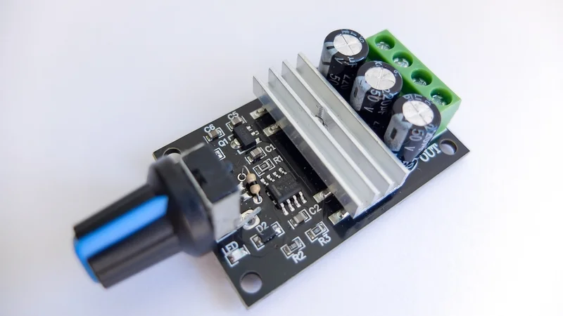
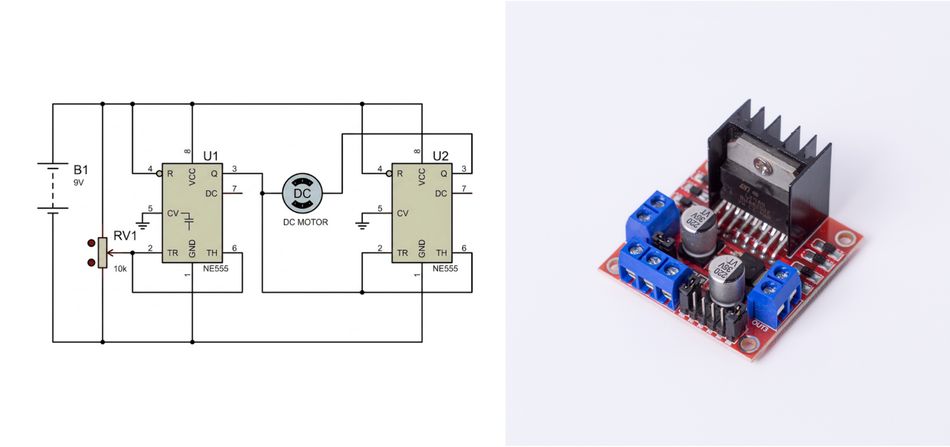
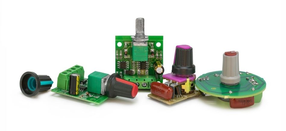
DC Motor Speed Controller Board
Key Takeaways
PWM Speed Regulation: The average voltage applied to the motor windings is directly controlled by the duty cycle of a pulse-width-modulated (PWM) signal, changing the motor speed without wasting power in the form of heat.
Driver Selection Criteria: Integrated drivers power small brushed motors up to 48 V and 4 A. High-power brushless drives utilize dedicated gate drivers or highly integrated microcontrollers with on-die transistor drivers to handle three-phase motor commutation.
H-Bridge Directional Control: The full bridge consisting of four MOSFETs enables bidirectional motor control, braking, and coasting. Activating specific transistor pairs dictates current flow through the windings to control rotation direction and active stopping.
Current Sensing Integration: Low-side shunt resistors and programmable-gain amplifiers monitor motor current. Sampling current precisely before the end of the PWM on-period allows accurate measurements for stall detection and over-current protection.
Sensorless Phase Commutation: Sensorless brushless control relies on monitoring the unpowered phase in a six-step sequence. Comparing the back-EMF zero-crossing against half the DC bus voltage determines the precise moment to switch phases.
Common Pitfalls: Forgetting flyback diodes on discrete drivers, using PWM frequencies below 15 kHz that cause audible noise, neglecting dead time and shoot-through, choosing a supply voltage outside the driver's range, or omitting thermal pads. Always consult the datasheet for gate drive strength, supply requirements and maximum current.
Introduction
Modern electric motors power robotics, medical devices, conveyors, e-bikes, actuators, and countless embedded motion systems. In these applications, DC motor speed control is essential for maintaining efficiency, torque stability, smooth acceleration, and long service life. Pulse-Width Modulation (PWM) is the most widely used technique because it regulates the effective motor voltage by rapidly switching the supply on and off.
Unlike linear regulation, which dissipates excess energy as heat, PWM-based DC motor speed control keeps the semiconductor switches operating primarily in fully on or fully off states, reducing power loss and improving thermal performance. For brushed DC motors, PWM directly controls armature voltage and torque response. For BLDC drives, PWM works with electronic commutation, gate drivers, current sensing, and feedback algorithms.
This article explains practical DC motor speed control techniques for both brushed and BLDC systems, covering design principles, control methods, and engineering considerations behind reliable motor speed control.
DC Motor Basics
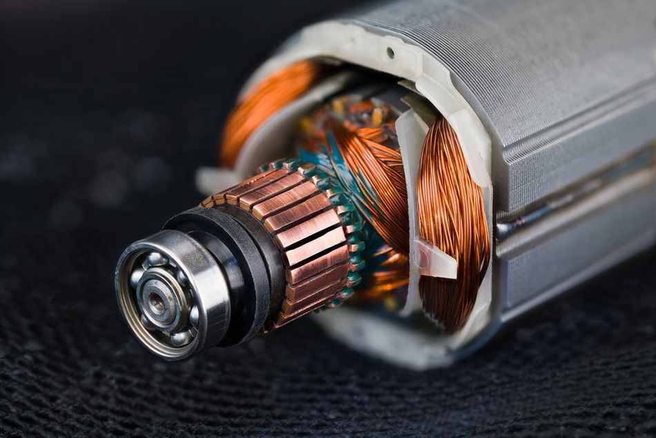
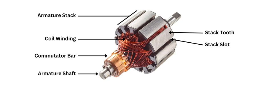
The brushed DC motor consists of a stator with permanent magnets, a rotor with wound coils and a mechanical commutator. Once the rotor spins, the commutator reverses current through the coils, keeping the rotor field perpendicular to the stator field and generating continuous rotation. Reversing the supply polarity swaps the rotor poles and changes the rotation direction [1].
The key electrical and mechanical relationships include:
Torque Constant: Torque is proportional to armature current. In permanent-magnet DC motors, the torque constant is closely related to the back-EMF constant.
Back-EMF: Once the rotor spins, it generates a voltage that opposes the applied input voltage. This counter-voltage is called back electromotive force, or back-EMF. The speed of a DC motor depends on the balance among the applied voltage, back-EMF, load torque, and armature current.
Electrical Equivalent Circuit: The motor can be modelled as armature resistance and inductance in series with the back-EMF generator. During PWM switching, the inductance smooths the current, creating an exponential rise and fall. Higher PWM frequency reduces ripple amplitude.
Speed-Torque Curve: Speed is highest, and current is minimal at no load. Once load torque increases, speed decreases approximately linearly while current increases. In practical systems, brush friction, heating, magnetic saturation, and current limits reduce usable torque.
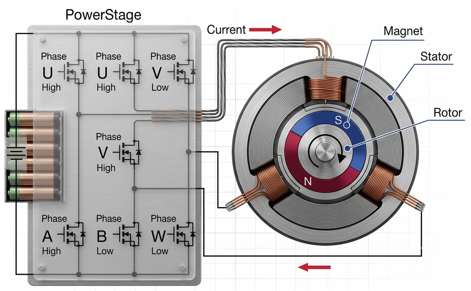
Brushless DC Motors: BLDC motor uses a three-phase stator with coils energised electronically and a rotor with permanent magnets. There are no brushes; commutation is performed by an inverter controlled by Hall sensors or back-EMF detection. The torque constant and back-EMF constant still apply, but the torque ripple depends on the commutation scheme, such as trapezoidal, sinusoidal, or field-oriented control (FOC).
Recommended Reading: Brushless vs Brushed Motor: Engineering Trade-offs and Design Decisions
Why PWM Beats Linear Control?
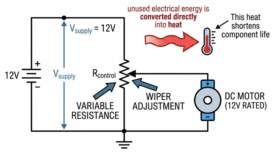
Linear speed control uses a variable resistor or linear regulator to drop voltage across the motor. The linear control method is simple but inefficient, as unused electrical energy is converted directly into heat. If a 12 V motor is slowed to 6 V using a resistor, half the supply energy is dissipated as heat. In high-current applications, this heat shortens component life and reduces efficiency.
PWM control avoids this limitation by switching the motor supply rapidly on and off. Instead of continuously dropping voltage, a DC motor controller adjusts the duty cycle of the switching waveform. The average motor voltage can be approximated as:

where D is the duty cycle and V (supply) is the input supply voltage. Once the switch is fully on, its resistance is very low. When it is off, current flow is blocked. Because the switch is either fully on (low resistance) or off, conduction losses are minimal; energy is delivered in discrete packets, and the motor inductance filters the current.
PWM also provides better dynamic response. The inductance ensures the current does not decay completely between pulses, maintaining torque at low duty cycles. Once the duty cycle approaches zero, the motor naturally freewheels; as it approaches unity, the motor sees nearly the full supply voltage.
Numerous practical controllers use a potentiometer, analog input, Arduino, or digital command signal to set the desired speed reference. However, this input does not directly carry motor power. It only tells the control circuit what duty cycle to generate. The actual switching is handled by a motor driver, MOSFET, or power stage that controls the current delivered to the motor.
PWM Theory and Frequency Selection
The PWM signal alternates between ON and OFF states at a fixed switching frequency. The duty cycle D is the fraction of one period where the signal is ON. For a given supply voltage, the average voltage applied to the motor can be approximated as:

In a brushed motor, the inductance and resistance determine the current ripple. Higher switching frequencies reduce ripple but increase MOSFET switching losses. Conversely, a frequency too low can produce audible acoustic noise or saturate the core.
For small low-voltage motors, practical PWM frequencies are commonly selected in the 10–25 kHz range. This keeps the switching frequency above much of the audible range while limiting switching losses. For BLDC and higher-inductance motor drives, frequencies around 20–50 kHz may be used, depending on the inverter, MOSFET gate charge, winding inductance, and current-control requirements.
To avoid audible noise, keep the fixed switching frequency above 15 kHz. Ultrasonic frequencies (>20 kHz) are inaudible but may increase switching loss. MOSFETs with low gate charge and drivers with strong gate currents (hundreds of mA) help maintain efficiency at higher frequencies. It is necessary to check the maximum switching frequency of the driver and the inductance of the motor when choosing a fixed switching frequency.
Recommended Reading: What Is a PWM Signal? Fundamentals and Practical Applications for Engineers
H-Bridge for Bidirectional Control
The full H-bridge uses four MOSFETs (Q1–Q4) to provide bidirectional speed and directional control over a DC motor.
By selectively activating pairs of switches, the H-bridge alters the polarity of the voltage applied across the motor terminals, enabling four primary operational states:
Forward Mode: Activating the high-side switch Q1 and low-side switch Q4 (while keeping Q2 and Q3 deactivated) forces current to flow through the motor in one direction, establishing forward rotation.
Reverse Mode: Activating the high-side switch Q3 and low-side switch Q2 (while keeping Q1 and Q4 deactivated) reverses the current path, inducing counter-rotation.
Braking Mode (Dynamic Braking): Deactivating both high-side switches (Q1, Q3) while simultaneously activating both low-side switches (Q2, Q4) shorts the motor terminals together. The back-EMF generated by the spinning rotor creates a reverse current that rapidly dissipates the kinetic energy as heat, braking the motor.
Coasting Mode: Deactivating all four switches disconnects the motor from both the supply voltage and ground. The motor freewheels to a stop, governed purely by mechanical friction and load inertia.
The high-side MOSFETs require a gate driver capable of generating a gate voltage above the supply, typically using a bootstrap capacitor or charge pump. The dead-time insertion prevents shoot-through by ensuring that one MOSFET turns off fully before its complementary device turns on. The PWM control methodologies include:
Sign-Magnitude Control: One leg of the H-bridge is driven to a static logic level to dictate the direction of rotation (the "sign"), while the complementary leg is modulated with a PWM signal to control the average terminal voltage and rotational speed (the "magnitude").
Locked Anti-Phase Control: Both half-bridge legs are continuously modulated 180° out of phase with each other. The net average voltage across the motor is zero at 50% duty cycle, holding the rotor stationary. Increasing or decreasing the duty cycle drives the motor forward or backwards. This approach improves system linearity around zero speed, but it doubles the effective switching frequency and current ripple.
Shoot-Through and Dead Time: If both MOSFETs in a half-bridge turn on simultaneously, the supply rails short and large shoot-through currents can damage components. Drivers such as DRV8701 and DRV8323 incorporate configurable dead time: the DRV8701 gate driver supports external MOSFETs with a maximum source current of 150 mA and sink current of 300 mA [2]. The ST L6203 includes built-in cross-conduction protection for its integrated DMOS H-bridge [3]. It is advisable to follow the dead-time recommendations in the datasheet or use blanking timers in the firmware.
Recommended Reading: H-Bridge Motor Driver: Complete Engineering Guide to Topologies, ICs, and PCB Layout (2026)
Motor Driver ICs
Selecting the right motor driver is critical. Engineers should match supply voltage, continuous current, peak current, PWM frequency capability, current-sense features and protection mechanisms to the motor's requirements.
TI DRV8871
The DRV8871 is an integrated H-bridge for brushed motors. It operates from 6.5 V to 45 V and delivers up to 3.6 A peak current [4]. The input supports PWM frequencies from 0 Hz (DC) to 200 kHz, though TI suggests using 20 kHz to minimise losses. It features internal current regulation and over-current protection. In simple applications, the DRV8871 can directly drive a motor with a microcontroller PWM and direction pin.
TI DRV8323
The DRV8323 is a three-phase gate driver for BLDC or PMSM motors. It supports three control modes (6×, 3× or 1× PWM) for trapezoidal, sinusoidal or FOC control. Its supply range is 6–60 V, and it includes three low-side current-sense amplifiers with programmable gain (5, 10, 20 or 40 V/V) [2]. The on-chip charge pump powers high-side N-MOSFETs; design guidelines emphasise selecting MOSFET gate charge Q (g) such that Q (g) < I (CP) / f (PWM). For example, with an 8 V gate drive and 45 kHz PWM, the total gate charge must be less than 333 nC [2]. The driver also features shoot-through protection, adjustable dead time, and 100% duty-cycle operation.
TI DRV8701
The DRV8701 is a dual-channel gate driver for external MOSFETs (a full H-bridge or two half-bridges). It operates from 5.9 V to 45 V and provides up to 150 mA gate-source and 300 mA gate-sink current [2]. It integrates a current-shunt amplifier with a gain of 20 V/V and an adjustable current-regulation loop; the design section shows that, with a 7 V supply and 40 kHz PWM, the driver can drive MOSFETs with gate charge less than 200 nC [2]. The DRV8701 includes two low-dropout regulators (4.8 V and 3.3 V) to power microcontrollers, making it suitable for compact designs.
ST L6203 and STSPIN Series
The ST L6203 is an integrated DMOS full-bridge driver rated up to 48 V and 4 A RMS with 5 A peak. It includes cross-conduction protection and TTL-compatible inputs and can operate up to 100 kHz. The STSPIN32F0 is a more advanced BLDC controller integrating three half-bridge gate drivers (600 mA source/sink), an STM32 Cortex-M0 microcontroller, a 3.3 V buck regulator, a 12 V LDO and four rail-to-rail op-amps. It handles 8–45 V supplies and implements field-oriented control with over-current and under-voltage protection. Such integration simplifies design of compact BLDC controllers.
Allegro A4988
The A4988 microstepping driver is widely known for stepper motors. It supports up to ±2 A output current and operates from 8 V to 35 V [5]. Features include microstepping down to 1/16-step, synchronous rectification, under-voltage and over-temperature protection, and automatic current decay mode selection [5]. Although primarily for steppers, it demonstrates integrated current control and PWM choppers; many of the same concepts apply to brushed DC motors.
Infineon IFX9201 and TLE987x
IFX9201SG is a general-purpose H-bridge rated for 5–36 V supply and 6 A continuous current. The outputs can be PWM-modulated up to 20 kHz; the device includes a direction pin and a PWM input, with a typical chopper current limit of 7 A. Built-in diagnostics (SPI and status flag) and protections (short-circuit, over-temperature, under-voltage) make it suitable for automotive actuators.
The TLE987x/6x family integrates a 32-bit Arm Cortex-M microcontroller, non-volatile memory, communication interfaces and high-side/low-side NFET drivers on a single die. The devices are designed for 3-phase BLDC motors such as cooling fans, pumps and window lifts [6]. Having the microcontroller and gate drivers in one package reduces PCB area and simplifies functional safety by enabling closed-loop speed control, LIN or PWM interfaces, and robust protection. The hardware design guideline highlights the integrated power supply rails (5 V and 1.5 V regulators) and the need to size the charge-pump components based on the PWM frequency and MOSFET gate charge to maintain the gate-drive voltage.
Current Sensing and Current-Mode Control
Accurate current measurement is critical for torque control, protection and sensorless speed estimation. The three common techniques include:
Shunt Resistor with Differential Amplifier: The low-value resistor, usually in the milliohm range, is placed in series with the motor supply, phase, or return path. The small voltage drop across the shunt is amplified by a differential or current-sense amplifier and then measured by an ADC. In PWM drives, current is often sampled near the end of the PWM on-time, when the measured value is more stable and representative of peak winding current.
Integrated Current Sense Amplifier: Many modern motor driver ICs include built-in current-sense amplifiers. These amplifiers reduce external component count, improve layout simplicity, and provide selectable gain for different current ranges. Integrated sensing is especially useful in compact low-voltage motor drives, where PCB space, noise immunity, and protection response time are important.
Hall-Effect Current Sensor or CSA: For higher-current systems or applications requiring galvanic isolation, Hall-effect current sensors provide an output voltage proportional to motor current without placing the measurement circuit directly in the high-current path. These sensors are commonly used in BLDC, automation, and industrial drive systems where isolation and robustness are required.
The current-mode control loops regulate motor current directly. In a hysteretic current-mode drive (e.g., stepper driver A4988), the driver turns off the MOSFET when current exceeds a threshold and turns it on when current falls below a lower threshold. This produces a triangular current waveform whose average is proportional to torque. Peak-current regulation protects the motor during startup or stall conditions.
Closed-Loop Speed Control
Open-loop PWM control modulates motor speed but does not compensate for supply variations or load changes. Closed-loop control uses feedback to maintain desired speed across varying loads.
The common feedback devices include:
Encoders: Optical or magnetic encoders produce pulses proportional to rotor position. Counting pulses over time yields speed, while quadrature encoders also indicate direction. A microcontroller implements a PID controller that adjusts the PWM duty cycle to reduce speed error.
Potentiometers: The potentiometer can serve as a user interface to set the desired speed; the ADC reads its voltage, and the controller adjusts the PWM accordingly. However, the potentiometer does not provide feedback by itself.
Back-EMF Sensing: Back-EMF can also be used for speed or position estimation. In brushed DC motors, back-EMF measurement can help detect motor stopping, braking behavior, or direction-change timing. For BLDC motors, sensorless control estimates position from back-EMF zero-crossings
PID Controller Implementation: The discrete proportional–integral–derivative (PID) controller calculates an error:

The proportional term provides immediate correction, the integral term eliminates steady-state error, and the derivative term improves damping. Tuning methods include Ziegler–Nichols or Loop-Shaping. In resource-constrained microcontrollers, only proportional–integral (PI) control is often used. High-resolution encoders (e.g., 1000 pulses per revolution) allow precise speed measurement but increase processing demand. For sensorless BLDC drives, the controller must also manage commutation timing.
Recommended Reading: PID Controller & Loops: Comprehensive Guide to Understanding and Implementation
BLDC Speed Control Techniques
BLDC motors require commutation sequencing for each phase.
The three common approaches include:
Trapezoidal Six-Step Control: In six-step control, two phases conduct while the third phase remains unpowered. The commutation pattern changes every 60 electrical degrees. In sensorless operation, the open phase can be monitored for back-EMF zero crossing, which indicates rotor position for the next commutation event. This method is simple, computationally light, and suitable for many brushless DC motors, but it can produce torque ripple, vibration, and acoustic noise.
Sinusoidal PWM: Sinusoidal commutation drives the three motor phases with sinusoidal current references. This reduces torque ripple compared with six-step control and improves smoothness at moderate and low speeds. It requires rotor-position information from Hall sensors, an encoder, or an estimator. The motor driver generates complementary PWM signals for the inverter switches, while the controller adjusts the phase voltage or current to meet the required speed and torque.
Field-Oriented Control (FOC): FOC transforms three-phase motor currents into a rotating reference frame with direct-axis and quadrature-axis components. The q-axis current controls torque, while the d-axis current controls flux and is often regulated near zero in permanent-magnet BLDC drives. FOC provides precise torque control, low ripple, and high efficiency, but it requires fast current sensing, accurate rotor-angle estimation, and a capable microcontroller.
Sensors vs Sensorless: Hall sensors provide straightforward commutation feedback and reliable low-speed startup. Sensorless BLDC control reduces sensor costs and wiring, but it relies on measurable back-EMF, which makes startup and very low-speed operation more difficult. In field-oriented control, advanced estimators such as sliding-mode observers or phase-locked loops estimate rotor angle from voltage and current measurements.
Common Mistakes in PWM Motor Control
The following mistakes are common in DC motor speed controller designs and should be addressed early during schematic, PCB, and firmware development.
Omitting Flyback Diodes or Recirculation Paths: Once the motor current is interrupted, the inductance produces a voltage spike. Integrated drivers include synchronous rectification, but discrete MOSFET designs require external flyback diodes or body diode conduction paths.
Incorrect PWM Frequency Selection: Frequencies below 10–15 kHz create audible whine; extremely high frequencies (>50 kHz) increase switching loss and may exceed the charge pump capacity of the driver [1].
Ignoring Motor Inductance: Low-inductance motors (e.g., coreless) need higher PWM frequencies to keep current ripple acceptable; high-inductance motors can be driven at lower frequencies. Failing to account for inductance can lead to torque ripple and overheating.
Ground Bounce and Poor Layout: High di/dt currents cause ground bounce and electromagnetic interference. Use proper decoupling, short traces and a solid ground plane. Keep sense resistors close to the driver and route gate traces carefully.
No Current Limit or Over-Temperature Protection: Stall currents can be several times the rated current. Drivers like DRV8323, DRV8701 and IFX9201 offer adjustable over-current thresholds; integrate these into your design.
Improper Thermal Management: Many drivers require a thermal pad to dissipate heat. Under-sized PCBs or lack of copper pours can cause overheating and reduce reliability.
Application Contexts
PWM DC motor speed controllers find use across many industries:
Robotics Joints and Actuators
Robotics systems commonly use low-voltage motor drives in the 12–48 V range, with current levels from a few amps to 20 A or more. In robotic joints, grippers, mobile platforms, and actuators, encoders are often used for precise position and speed feedback. Closed-loop control allows the controller to maintain motion accuracy even when load torque changes. Depending on the design, the motor may be a brushed DC motor, gear motor, servo-style actuator, or BLDC motor.
Drone Electronic Speed Controllers
Drone ESCs typically drive sensorless brushless DC motors from battery packs ranging from 3-cell systems around 12 V to higher-voltage packs approaching 48 V. Current demand can reach 20–80 A depending on propeller size and thrust requirements. These controllers often use high-frequency PWM, commonly around 30–50 kHz, to reduce torque ripple and improve efficiency. MOSFET selection, PCB layout, current sensing, and thermal design are critical because the motor driver must handle rapid acceleration, high switching losses, and fast load changes.
Automotive Seat, Window, and Throttle Motors
Automotive comfort and control systems often use 12 V brushed DC motors for seats, windows, mirrors, locks, and throttle mechanisms. Typical current levels range from about 3–15 A, but stall current can be much higher. Bidirectional H-bridge control is required for forward and reverse movement, while current sensing helps detect end stops, obstruction, or stalled conditions. Fault diagnostics, thermal protection, and robust operation under varying supply voltage are especially important in vehicle environments.
Industrial Conveyors and Pumps
Industrial conveyors, pumps, fans, and small automation equipment often use 24 V or 48 V motor drives with current ratings of 5–50 A. In these systems, closed-loop speed regulation helps maintain constant belt speed, flow rate, or process output as mechanical load changes. Higher motor inductance often allows moderate PWM frequencies in the 10–20 kHz range, reducing switching losses while keeping current ripple acceptable. Protection against overload, overheating, and supply disturbances is important for long operating life.
E-Bikes and Personal Mobility
E-bikes, scooters, and compact mobility systems commonly use 36 V or 48 V BLDC hub motors, often with currents up to 30 A or higher during acceleration. Smooth torque delivery is important for rider comfort, so many controllers use sinusoidal commutation or field-oriented control. Sensorless algorithms can reduce wiring and cost, while Hall sensors improve low-speed startup and hill-climb performance. Current limiting is also important for protecting the battery pack, MOSFETs, and motor during high-load operation.
Extension to AC Motor Drives
The same switching principles also apply to AC motor drives and variable-frequency drives for induction or permanent-magnet AC machines. However, these systems require additional hardware, higher-voltage isolation, inverter stages, and vector-control algorithms. For single-phase or mains-powered equipment, designers must also account for VAC ratings, rectification, safety isolation, and regulatory requirements.
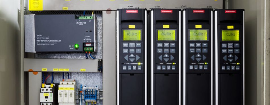
The same principles extend to AC motor drives and variable-frequency drives for induction motors, but those designs require additional hardware and vector control algorithms.
Recommended Reading: Motor Control Design: End-to-End Methodology
Conclusion
PWM-based DC motor speed controllers offer an efficient and flexible way to control speed and torque in brushed and brushless motors. By modulating the duty cycle, the average voltage seen by the motor scales linearly with desired speed. Using an H-bridge topology, one can implement forward, reverse, braking and coast modes and integrate current sensing to protect the motor. Selecting the right driver IC, considering supply voltage, current rating, gate drive strength and built-in protection, is essential for reliable operation. Closed-loop control with encoder or back-EMF feedback improves speed accuracy under load and enables advanced techniques such as field-oriented control.
Looking ahead, smart motor drivers with integrated microcontrollers and firmware will become more prevalent, reducing development time and improving functional safety. The wide-bandgap semiconductors (SiC and GaN) enable higher PWM frequencies with lower switching losses, opening possibilities for higher-efficiency, lighter motor drives.
Frequently Asked Questions
Q. How does PWM control DC motor speed?
A. PWM controls motor speed by rapidly switching the supply on and off. The duty cycle determines the average motor voltage. Higher duty cycle increases speed, while motor inductance smooths current for steadier torque.
Q. What PWM frequency should I use for a DC motor?
A. Use a PWM frequency high enough to avoid audible noise but low enough to limit switching loss. Many brushed motors work well around 10–25 kHz, while BLDC and high-speed drives may use 20–50 kHz.
Q. Do I need an H-bridge for DC motor speed control?
A. For unidirectional control, a half-bridge or low-side switch is sufficient. For bidirectional rotation, braking and regenerative operation, a full H-bridge with four MOSFETs is required. Integrated H-bridge drivers (e.g., DRV8871 or L6203) simplify the design.
Q. Can I control speed with a potentiometer alone?
A. The potentiometer can set the speed reference, but it should not carry motor current directly. In practical control systems, the potentiometer provides an analogue input, while a motor driver generates PWM to enable efficient variable-speed control.
Q. What is the difference between brushed and brushless DC motor speed control?
A. Brushed motors use mechanical commutation and can be driven with simpler PWM circuits. Brushless DC motors require electronic commutation, usually via a three-phase inverter, with Hall-sensor, back-EMF, or encoder feedback.
Q. How do I add closed-loop speed control to a DC motor?
A. Use an encoder or back-EMF sensor to measure speed, compute the error between desired and measured speed and adjust the PWM duty cycle via a PI or PID controller. Current sensing can provide torque feedback and protect against stalls.
References
[1] NXP Semiconductors. AN10513 Brushed DC Motor Control Using the LPC2101 [Cited 2026 June 8]; Available at: Link
[2] Texas Instruments. DRV8701 Dual-Bridge Motor Driver Datasheet [Cited 2026 June 8]; Available at: Link
[3] Battle Born Batteries. BB10012 Deep Cycle Battery Specifications [Cited 2026 June 8]; Available at: Link
[4] Texas Instruments. DRV8871 Brushed DC Motor Driver Datasheet [Cited 2026 June 8]; Available at: Link
[5] Allegro Microsystems. A4988 Microstepping Motor Driver Datasheet [Cited 2026 June 8]; Available at: Link
[6] Infineon Technologies. IFX9201SG H-Bridge Driver Datasheet [Cited 2026 June 8]; Available at: Link
in this article
1. Key Takeaways2. Introduction3. DC Motor Basics4. Why PWM Beats Linear Control?5. PWM Theory and Frequency Selection6. H-Bridge for Bidirectional Control7. Motor Driver ICs8. Current Sensing and Current-Mode Control9. Closed-Loop Speed Control10. BLDC Speed Control Techniques11. Common Mistakes in PWM Motor Control12. Application Contexts13. Conclusion14. Frequently Asked Questions15. References