Brushless vs Brushed Motor: Engineering Trade-offs and Design Decisions
This article provides a technical overview of the brushless vs brushed motor paradigm, equipping design engineers with the analytical framework necessary to make informed, application-specific decisions.

18 Mar, 2026. 14 minutes read
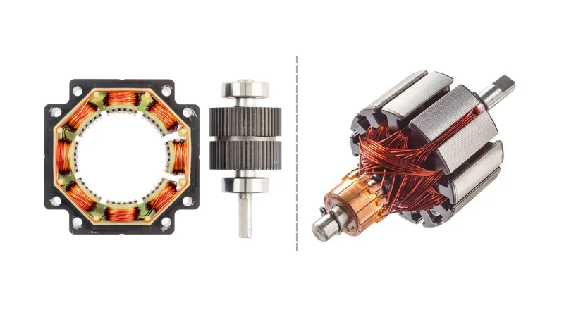
Brushless vs Brushed Motor
Key Takeaways
Efficiency Gap is Significant: Brushed motors typically operate at 75-80% efficiency, while high-quality BLDC motors achieve 85-93% efficiency. Eliminating brush friction reduces copper and mechanical losses, contributing to up to 600 W energy savings per 5 hp drive annually.
Lifespan and MTBF: Brush wear limits brushed motors to 1,000-8,000 h, depending on design, whereas BLDC motors can operate for tens of thousands of hours, with bearings becoming the primary failure mode.
Power Density and Torque: Surface-mounted BLDC motors deliver 0.75-1.05 Nm/kg torque density while interior permanent-magnet designs reach 1.05-1.45 Nm/kg. Brushed motors offer lower torque density (often <0.7 Nm/kg), and their torque falls off at higher speeds.
Cost vs Total Ownership: A 5 hp brushed motor system costs 40-60% less initially (approximately USD 400-1,400) than an equivalent brushless system (approximately USD 1,200-3,200). However, energy and maintenance savings allow BLDC drives to break even in 12-18 months and reduce the total cost of ownership by 31% over 10 years.
Control Complexity and EMI: Brushed motors require simple H-bridge circuits, but brush arcing produces electromagnetic interference (EMI) and limits speeds. BLDC motors employ Hall sensors and sophisticated field-oriented control (FOC) algorithms; this increases driver cost (approximately USD 10-50) but yields smoother torque, quieter operation, and better EMI compliance.
Introduction
DC motors enable high torque at low voltage and have been the preferred actuation solution for decades. However, the comparison of brushless vs brushed motor technologies remains one of the most important decisions engineers face during system design.
Brushed DC motors use a mechanical commutator and carbon brushes to reverse current in the armature windings. The simplicity of this arrangement results in low manufacturing cost and straightforward control. Yet mechanical commutation introduces friction, wear and electrical arcing that diminish efficiency and shorten service life.
Brushless DC motors eliminate the commutator by mounting permanent magnets on the rotor and moving the windings to the stator. This architecture improves efficiency and enables very high power densities. However, the need for sophisticated control electronics increases cost and design complexity.
For design engineers, selecting a brushless vs brushed motor involves balancing efficiency, torque density, size, reliability, and cost while meeting application-specific constraints such as battery life, duty cycle, environmental conditions, and electromagnetic compatibility. The following sections dissect the underlying physics and recent data to help engineers make informed choices among brushless vs brushed motors.
How Brushed DC Motors Work?
Commutator and Brush Mechanism
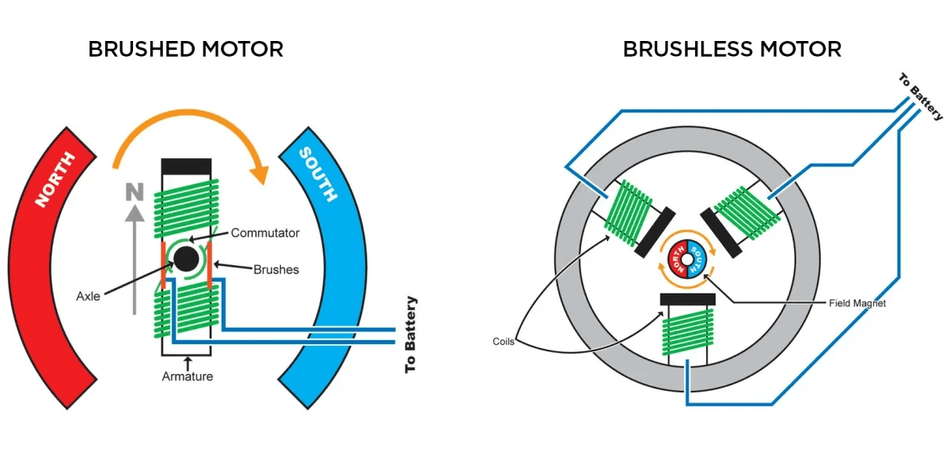
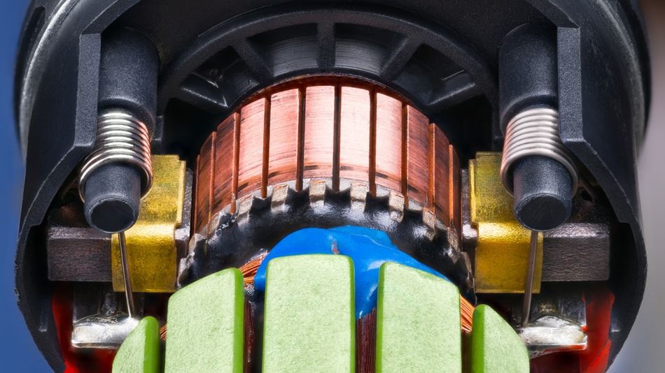
In brushed DC motors, the rotor, often called the armature, contains multiple motor windings connected to a segmented copper commutator mounted on the shaft. The stationary carbon brushes press against the commutator segments, creating an electrical contact that allows electrical current from the DC power supply to reach the rotating windings. Once current flows through the armature conductors, they interact with the magnetic field produced by the stator or permanent magnets, generating torque according to the Lorentz force principle.
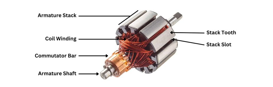
Once the rotor rotates, the commutator periodically reverses the polarity of the armature current. This switching process maintains the torque direction and sustains continuous rotation. Because commutation occurs through physical contact, friction develops between the commutator and brushes. This leads to wear and tear, gradual brushes wear, and the formation of arcing at the contact interface.
To improve durability, brush materials are commonly formulated from carbon-graphite composites or precious metal alloys designed to minimize resistance and maintain stable contact pressure. Brush sparks are also a potential ignition source in flammable environments.
Torque-Speed Characteristics
The performance of brushed DC motors is typically represented by a linear torque-speed relationship under constant supply voltage. The motor produces maximum torque at a standstill, known as stall torque, determined primarily by armature resistance and applied voltage. High starting torque occurs because the electrical energy supplied initially encounters minimal back electromotive force (back-EMF). Once the rotor accelerates and motor speed increases, the generated back-EMF opposes the applied voltage, reducing armature current and consequently lowering torque.
This predictable relationship allows simple speed control through voltage variation or pulse-width modulation. However, friction and commutator losses reduce efficiency at high speeds. Manufacturers often rate brushed motors at 50% of stall torque for continuous operation to prevent overheating. Torque ripple is low due to many commutator segments, which benefits applications requiring smooth low-speed operation.
Thermal Behaviour and Efficiency
The efficiency of electric motors based on brush commutation is influenced by multiple loss mechanisms. Resistive losses in the motor windings (I²R losses), friction between the brushes and commutator, and energy lost through arcing all contribute to energy loss. Typical brushed DC motors achieve approximately 75–80% electrical-to-mechanical conversion efficiency under rated conditions.
The ironless core designs used in premium models can slightly improve efficiency by eliminating eddy current losses at the expense of higher cost. Thermal performance is governed by the ability to dissipate Joule heat through the housing. Because the heat source (armature and brushes) rotates inside the rotor, cooling is inefficient.
The surface temperatures can rise above 100°C at overload conditions, degrading insulation and causing demagnetisation. Frequent start-stop duty cycles exacerbate heating because inrush current heats the winding. Therefore, derating for continuous duty is essential. Many industrial brushed motors specify a maximum ambient of 40°C with thermal cut-outs to prevent damage.
Winding Configurations
Brushed DC motors are further categorised by the way field windings are connected:
Series-Wound: The field winding is connected in series with the armature. High starting torque results, but speed varies considerably with load. These motors are common in automotive starter systems and traction drives.
Shunt-wound: The field winding connects in parallel with the armature. They offer better speed regulation but lower starting torque, used in blowers and conveyors.
Compound: Both series and shunt windings are used to combine high starting torque and good speed regulation.
Permanent-Magnet Brushed Motors: The stator contains permanent magnets instead of field windings. They deliver higher efficiency and compact size but have limited torque and require precise commutator design.
Regardless of the configuration, brush wear remains the limiting factor; typical brush life is 1,000 - 3,000 hours. High-performance carbon-silver brushes can extend life to 8,000 hours, but at increased cost. Replacement intervals depend on current density, duty cycle, and commutator surface finish.
Recommended Reading: AC vs DC Motor: Unpacking Their Engineering Applications and Innovations
How Brushless DC Motors Work?
Electronic Commutation and Inverter Operation
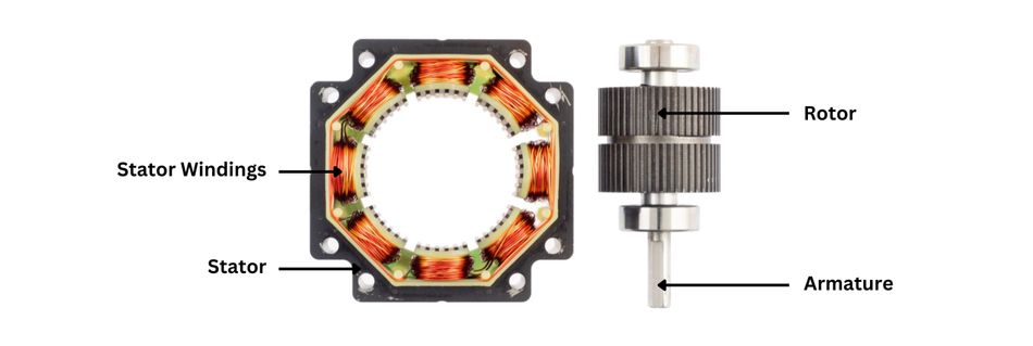
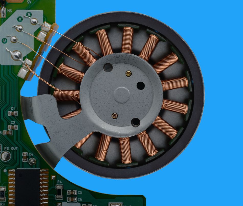
Unlike brushed DC motors, brushless motors eliminate the mechanical commutator and carbon brushes entirely. Instead, the motor windings are placed on the stationary stator, while the rotor carries permanent magnets. This structural change allows the motor to operate using electronically commutated switching rather than physical contact.
In brushless DC motors, an electronic controller or motor controller performs the commutation process. The three-phase inverter sequentially energises stator coils to create a rotating magnetic field. The rotor magnets align with this moving field, producing torque and continuous rotation.
The two primary control strategies are used in modern BLDC motor systems. The first method is a six-step (trapezoidal) commutation, which energizes phases in discrete steps. This approach is relatively low-cost and cost-effective, but it can introduce torque ripple and additional electrical noise. The second method is field-oriented control (FOC), where stator currents are precisely regulated to remain aligned with the rotor flux vector. FOC allows fine control of torque and speed but requires high-performance microcontrollers and current sensors.
Hall Sensors vs Sensorless Operation
The accurate rotor position detection is essential for proper electronic commutation. In many brushless motors, hall-effect sensors embedded in the stator detect magnetic field changes and provide discrete phase angle information. This approach supports efficient low-speed operation and starting torque but adds wiring and susceptibility to heat and vibration.
Sensorless BLDC motors estimate rotor position by measuring back-EMF or observing zero-crossings in phase voltages. While eliminating sensors reduces cost and improves reliability, sensorless techniques cannot produce torque at zero speed and require an open-loop start-up algorithm. Advanced sensorless FOC algorithms rely on flux observers and can achieve accurate low-speed control but demand high-speed digital signal processors (DSPs).
Back-EMF and Commutation Timing
The rotating permanent magnets induce back electromotive force (back-EMF) in the stator windings. For a BLDC motor with trapezoidal back-EMF, the ideal commutation sequence energises each phase for 120 electrical degrees, resulting in six commutation events per electrical revolution. [1]
For sinusoidal back-EMF designs (also called permanent-magnet synchronous motors, PMSMs), FOC uses Clarke and Park transformations to transform stator currents into the rotor reference frame and regulate torque. Precise commutation timing maximises torque per ampere and minimises copper and switching losses. Improper timing or phase imbalance increases harmonic content and iron losses, causing heating and noise.
Rotor Configurations: Inner vs Outer Rotor
BLDC motors may employ inner-rotor or outer-rotor (outrunner) geometries. The inner-rotor motors place the rotor at the centre with the stator surrounding it. They provide higher speeds, lower inertia, and better heat dissipation because the stator windings contact the housing. The outer-rotor motors position the permanent-magnet rotor around the stator. The large air-gap diameter yields higher torque at lower speeds and improved torque density, but the mass increases inertia and limits high-speed capability.
Surface-Mounted Permanent-Magnet (SPM) motors mount magnets on the rotor surface; they are easier to manufacture but suffer from moderate torque density. Interior Permanent-Magnet (IPM) designs embed magnets inside the rotor, enabling salient poles that increase flux and yield higher torque density (1.05-1.45 Nm/kg) and a wider constant-power speed range.
Recommended Reading: How Does a DC Motor Work? Unveiling the Power Behind Electric Motion
Brushless vs Brushed Motor: Head-to-Head Comparison
The following table summarises critical performance and cost parameters for brushed and brushless DC motors, synthesising data from recent literature and manufacturer datasheets. The values represent typical industrial devices rated for 50 W to 3 kW; actual numbers vary with design.
Parameter | Brushed Motor | Brushless Motor |
Efficiency | 75-80% under rated load; Premium ironless designs can reach 85%. | 85-93% due to electronic commutation; IPM BLDC motors achieve peak 89-93%. |
Lifespan / MTBF | 1,000 - 3,000 hours typical; 8,000 hours with high-end brushes. | Commonly >10,000 hours; some exceed 30,000 hours. |
Torque Density | 0.3-0.7 Nm/kg; Torque declines at high speeds. | SPM: 0.75-1.05 Nm/kg; IPM: 1.05-1.45 Nm/kg. |
Speed Range | Up to ~10,000 rpm; limited by brush arcing. | 6,000-50,000 rpm depending on design. |
EMI / Noise | Arcing and brush chatter generate EMI and audible noise. | Smooth electronic commutation reduces EMI. |
Cost (Motor + Driver) | ~USD 400-1,400 for a 5 hp system. | ~USD 1,200-3,200 for a 5 hp system. |
Maintenance | Brush replacement at 1,000-8,000 h; commutator servicing. | Very low; bearings only. |
Controllability | Simple voltage/PWM control. No position feedback needed. | Electronic commutation with FOC. Sensorless is possible above 5-10% rated speed. |
Size / Weight | Larger due to rotor windings and commutator. | Smaller and lighter; high power density. |
Thermal | Heat in rotating armature; max ambient ~40 C. | Stator-mounted windings dissipate heat effectively; -30 to +70 C. |
Efficiency and Power Density
Quantitative Efficiency Comparison
Friction at brush/commutator interfaces and electrical resistance in windings degrade the efficiency of brushed motors. The measurements from Assun Motor show a typical efficiency of 75-80% for brushed DC motors under nominal load. [2] Other surveys report ranges of 70% to 75% for low-cost models and up to 80% for premium designs. Ironless motors eliminate iron losses but still suffer from brush friction, limiting efficiency to approximately 85%.
BLDC motors achieve significantly higher efficiency because electronic commutation eliminates brush contact losses. Surface-mounted BLDC motors operating in trapezoidal mode typically achieve 85-90% efficiency. The IJIRT study on automatic gate motors measured peak efficiencies of 89.1-93.2% for interior permanent-magnet motors and 91.8% for surface-mounted motors, with average efficiencies near 89% across the operating range. [3] High-quality BLDC motors maintain efficiencies above 90% over a wide torque/speed envelope due to low iron losses and minimal copper losses at part load.
Power-to-Weight Ratio
Power density is crucial in mobile robotics, aerospace and electric vehicles. Because brushed motors carry windings and a commutator on the rotor, they add rotational inertia and reduce the power-to-weight ratio. Specific torque values rarely exceed 0.7 Nm/kg for small permanent-magnet brushed motors. In contrast, BLDC motors concentrate windings on the stator and use lightweight permanent-magnet rotors. The IJIRT paper reports that surface-mounted BLDC motors deliver 0.75-1.05 Nm/kg, while interior permanent-magnet BLDC motors reach 1.05-1.45 Nm/kg. These values correspond to approximately 37% improvement in torque density for IPM designs.
Loss Mechanisms
Copper losses (I2R) dominate both motor types and increase with current. For brushed motors, brush voltage drop (approximately 1-2 V) effectively increases resistance, lowering efficiency. Iron losses (hysteresis and eddy currents) occur as magnetic flux reverses in the iron core. BLDC motors incorporate high-grade silicon steel or amorphous metal laminations and can operate at higher switching frequencies, reducing core loss.
Friction and windage losses are minimal in BLDC motors because there are no brushes, and the rotor is often balanced to high precision. The switching losses in the inverter contribute to BLDC inefficiency, especially at high switching frequencies or low loads. At very high speeds (>20,000 rpm), eddy-current losses in rotor magnets reduce BLDC efficiency, which is why some high-speed motors use segmented magnets or carbon-fibre sleeves.
Recommended Reading: Stepper vs Servo Motors: What's the Difference?
Thermal Management and Reliability
Heat Generation and Cooling
Brushed motors generate heat at the brush/commutator interface and in the windings. The heat is concentrated in the rotating armature, making it difficult to dissipate to the outer housing. Many brushed motors incorporate thermal overload protectors that open the circuit when temperatures exceed 80-120°C.
BLDC motors have windings fixed to the stator, which is attached to the housing. This arrangement allows heat to be conducted directly to the motor body and dissipated into the environment. Because of their higher efficiency, BLDC motors run significantly cooler.
Research indicates that modern BLDC motor drives can operate reliably in ambient environments ranging from −30°C to +70°C, particularly when designed with sealed housings and high ingress protection ratings such as IP65 or higher. This thermal advantage directly contributes to their longer lifespans and improved reliability in demanding applications such as robotics, automation systems, and electric vehicles.
Failure Modes and MTBF
In brushed motors, brushes wear over time because continuous electrical contact between the carbon brushes and the commutator causes mechanical abrasion and electrical erosion. High rotational speeds, elevated current density, and frequent start-stop cycles accelerate this degradation. Once brushes gradually wear out, contact resistance increases, leading to additional heating, reduced energy efficiency, and unstable commutation.
Typical brush life ranges from approximately 1,000 hours for standard carbon brushes to 8,000 hours for higher-grade silver-graphite variants. Eventually, excessive wear disrupts the current flow to the armature, resulting in a loss of torque or intermittent operation.
In brushless DC motors, the absence of brushes removes this primary wear mechanism. Instead, mechanical bearings become the principal limiting component. [4] Bearing fatigue develops due to cyclic loading, lubricant degradation, and contamination. High-quality bearings in industrial BLDC motor systems commonly achieve service lifetimes exceeding 10,000 hours, while premium units can reach mean time between failures (MTBF) values of 30,000 hours or more. Because the rotor contains only permanent magnets and minimal electrical components, the risk of electrical wear is greatly reduced, contributing to the longer lifespan associated with brushless designs.
Maintenance and Reliability Comparison
The brushed DC motors require periodic inspection and replacement of carbon brushes, along with cleaning of the commutator surface to prevent debris accumulation and excessive electrical noise. These maintenance needs increase operational downtime and long-term ownership costs, particularly in industrial environments where motors operate continuously.
In contrast, brushless motors largely eliminate scheduled maintenance because there are no brushes or commutator components subject to mechanical erosion. Routine servicing typically involves only bearing lubrication or replacement after extended runtime. BLDC motor systems require less maintenance, offer improved reliability, and deliver more consistent high performance over time.
The economic analyses highlight the difference clearly! For example, a 5 hp industrial motor using brushed technology may incur annual maintenance expenses of around USD 800 due to brush replacement and service intervals. The comparable brushless DC motor typically requires less intervention, with estimated annual maintenance costs closer to USD 200. BLDC motors largely eliminate scheduled maintenance, with only bearing lubrication or replacement needed
Control Complexity and Driver Electronics
Simplicity of Brushed Motor Control
Brushed DC motors are electrically simple because they operate as two-terminal electric motors. H-bridge drivers composed of four power transistors allow bidirectional control and speed modulation via PWM. Since the commutator and carbon brushes handle current switching mechanically, no complex control system is required.
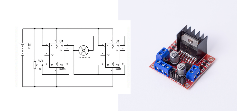
Low-cost controllers for small motors typically cost USD 2–5, making this technology attractive for prototypes, power tools, and low-complexity embedded applications. [5]
Sophistication of Brushless Motor Control
In brushless motors, commutation is performed electronically, requiring a three-phase inverter and dedicated motor controller. The controller sequences electrical current through the stator motor windings to generate a rotating magnetic field that interacts with the rotor permanent magnets.
Basic BLDC motor drives use six-step commutation, while advanced systems apply Field-Oriented Control (FOC). FOC enables precise control, higher efficiency, and smoother torque but requires fast processors, current sensing, and complex coordinate transformations.
Sensorless vs Sensored Trade-offs
The accurate rotor position detection is essential for electronically commutated brushless DC motors. The sensor systems use Hall sensors or encoders to directly measure the magnetic field of the rotor, enabling reliable startup and stable low-speed operation. Sensorless BLDC motor control estimates position by analyzing back-EMF in the stator windings. Modern sensorless FOC algorithms use model-based observers and high-frequency injection to estimate position, offering cost savings for volume production.
Recommended Reading: Motor Controller: Types, Design Considerations, Control Strategies, and Selection for Engineers
Application Selection Guide
When to Choose Brushed Motors?
Cost-Sensitive Consumer Products: Brushed DC motors remain a cost-effective solution when simple motor technology and minimal control-system complexity are priorities.
Short-Duration Duty Cycles: Applications, such as automotive window lifts, seat adjusters, and power locks, benefit from simple DC power operation and minimal maintenance.
Low-Speed, High-Torque Drives: Equipment like forklifts and starter motors uses brushed motors because they produce high starting torque when current flows directly through the armature and motor windings.
When to Choose Brushless Motors?
Electric Vehicles and Traction Drives: Brushless DC motors deliver high efficiency, regenerative capability, and excellent speed control across a wide operating range.
Drones and Aerospace: Lightweight BLDC motor designs offer high torque density and stable control using advanced motor controller systems.
Industrial Automation and Robotics: Electronically commutated motors enable precise control of rotor position and motion through advanced algorithms.
Medical Devices and HVAC Systems: Brushless motors operate with minimal electrical noise, less maintenance, and longer operational life.
Renewable Energy and Pumps: Continuous-duty systems benefit from superior energy efficiency and reduced energy loss.
Industry Examples
Automotive: Interior actuators often use brushed DC motors, while traction systems in electric vehicles rely on brushless motors or PMSM drives.
Robotics: High-performance robotic joints commonly use BLDC motor servos with feedback for accurate motion control.
Drones: Outrunner brushless motors provide high torque at lower speeds for propeller propulsion.
Industrial Systems: Conveyors and gantry drives increasingly adopt brushless motors for maintenance-free operation.
Medical and HVAC Equipment: Ventilators, surgical tools, and HVAC fans utilize brushless DC motors for quiet, reliable, and efficient performance.
Recommended Reading: Motion Control in Robotics: 4 Types of Motors for Industrial Robots
Design Considerations for Engineers
Electrical Ratings and Sizing
Selecting a motor requires matching voltage, current and power ratings to the power source and load. Engineers should consult torque-speed curves and derate continuous torque based on ambient temperature and cooling conditions. Proper sizing ensures electric motors operate within safe electrical current limits and prevents overheating of motor windings during continuous operation.
Thermal Derating and Environment
Thermal conditions strongly influence operational life and reliability. Brushed DC motors often require derating above 25–40 °C due to the heat generated at the carbon brushes and the commutator. In contrast, brushless motors dissipate heat more effectively through the stator, allowing operation from −30 °C to +70 °C when cooling is properly designed.
EMI and Regulatory Compliance
Brushed motors produce RF interference due to commutator sparking. Compliance with EMC standards (CISPR 25, EN 55014) may require the use of suppression capacitors, ferrite beads, and shielding. BLDC inverter switching can generate common-mode currents requiring proper layout and filtering.
Integration with Battery-Powered Systems
In battery-powered devices, efficiency directly affects runtime. Brushless DC motors typically deliver higher efficiency and lower energy loss, extending battery life in cordless equipment and mobile systems. Designers often integrate current limiting, soft-start circuitry, and regenerative braking within the motor controller to optimize power usage and protect electronics.
Supply Chain and Component Availability
Brushless motors rely on permanent magnets, often using rare-earth materials that can face supply constraints and price volatility. Brushed DC motors depend primarily on copper windings, steel laminations, and carbon brushes, which are generally more stable and widely available in global supply chains.
Conclusion
The decision between brushless and brushed motors hinges on application requirements. Brushed motors offer simplicity, low initial cost and high starting torque. They suit intermittent duty applications and cost-sensitive products. However, efficiency is limited to 75-80%, and service life to 1,000-8,000 hours.
Brushless DC motors deliver higher efficiency (85-93%), better torque density (up to 1.45 Nm/kg) and long MTBF (tens of thousands of hours). The system cost is higher, but the energy savings and reduced maintenance yield payback in 12-18 months, reducing total ownership cost by 31% over a decade.
Engineers should evaluate efficiency, torque density, cost, control complexity, thermal behaviour, EMI compliance and service life in the context of the specific application. The data presented here provide a quantitative foundation for the brushless vs brushed motor trade-off.
Frequently Asked Questions (FAQs)
1. What is the main difference between brushless and brushed motors?
A. Brushed motors use mechanical brushes and a commutator to switch current in the rotor windings, whereas brushless motors rely on electronic commutation with permanent magnets on the rotor. The absence of brushes in BLDC motors eliminates friction and wear, improving efficiency and service life.
2. Are brushless motors more efficient than brushed motors?
A. Yes. Brushed motors convert 75-80% of electrical power into mechanical output. Brushless motors achieve 85-93% efficiency, with some IPM designs exceeding 90% over a wide load range.
3. Why are brushless motors more expensive?
A. BLDC motors use rare-earth magnets and require three-phase inverters, microcontrollers, and position sensors. Energy savings and reduced maintenance often justify the investment over the product lifecycle.
4. How long do brushed motor brushes last?
A. The common carbon brushes last 1,000-3,000 hours, while silver-graphite brushes extend to 8,000 hours. Frequent starts and high currents reduce brush life.
5. Can I replace a brushed motor with a brushless motor?
A. Yes, but BLDC motors require a compatible controller, matching mechanical interfaces, and potentially adjusted gear ratios. The upgrade improves efficiency and lifespan but entails upfront cost and integration effort.
6. What applications are best suited for brushless motors?
A. EV traction drives, drones, industrial robots, medical pumps, HVAC fans and servo systems. High torque-to-weight ratio and low EMI make them ideal for battery-powered and aerospace applications.
References
[1] Onsemi. Trapezoidal Control of BLDC Motors [Cited 2026 March 16]; Available at: Link
[2] Assun Motor. Understanding DC Brushless Motor Efficiency & How to Test For It [Cited 2026 March 16]; Available at: Link
[3] IJIRT. Understanding DC Brushless Motor Efficiency & How to Test For It [Cited 2026 March 16]; Available at: Link
[4] Mosrac. What is a BLDC Motor? A Comprehensive Guide to Brushless DC Motors [Cited 2026 March 16]; Available at: Link
in this article
1. Key Takeaways2. Introduction3. How Brushed DC Motors Work?4. How Brushless DC Motors Work?5. Brushless vs Brushed Motor: Head-to-Head Comparison6. Efficiency and Power Density7. Thermal Management and Reliability8. Control Complexity and Driver Electronics9. Application Selection Guide10. Design Considerations for Engineers11. Conclusion12. Frequently Asked Questions (FAQs)13. References