CAN vs LIN: A Comprehensive Technical Analysis of Automotive and Industrial Network Protocols
This article provides a comprehensive technical comparison of CAN vs LIN, examining their architectures, use cases, and performance trade-offs.

24 Jun, 2025. 22 minutes read
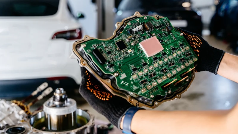
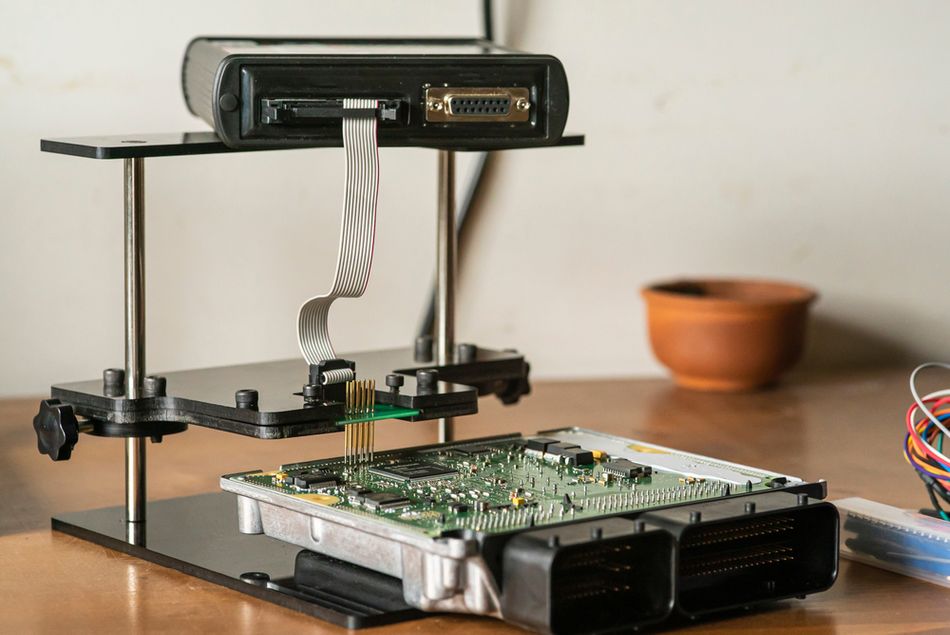
Electronic Control Unit (ECU) of Modern Electric Car
Introduction
In modern automotive and industrial systems, communication between electronic control units (ECUs) is critical for performance, safety, and efficiency. Two of the most widely used communication protocols enabling this are Controller Area Network (CAN) and Local Interconnect Network (LIN). CAN provides high-speed, robust communication for mission-critical operations, while LIN serves as a cost-effective solution for simpler, lower-priority tasks.
Understanding CAN vs LIN is essential for engineers and system architects tasked with designing scalable and reliable embedded networks. From transmission speed to fault tolerance and implementation complexity, the CAN vs LIN debate continues to shape the selection of network protocols in vehicles, factory automation, and smart devices. This article offers a comprehensive technical comparison of CAN vs LIN, exploring their architecture, use cases, and performance trade-offs.
In-Vehicle and Industrial Networking: The Genesis of CAN and LIN
The Evolving Landscape of Embedded Communication
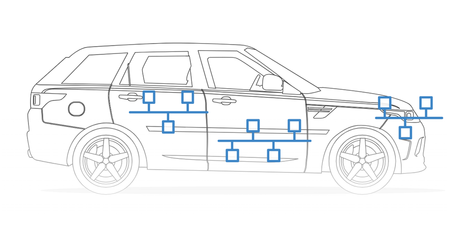
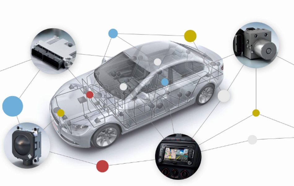
The exponential growth of electronic systems in automotive and industrial domains has transformed how machines communicate. Traditionally, embedded systems relied on point-to-point wiring, where each control signal was assigned a dedicated wire. While manageable in simple designs, this method quickly became impractical as the number of electronic control units (ECUs) and system complexity increased. Modern vehicles, for example, can host over 70 to 100 ECUs, each responsible for various functions such as powertrain control, active safety, infotainment, and body electronics. [1]
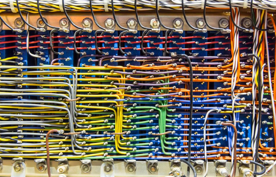
This wiring explosion resulted in greater vehicle weight, increased production costs, reduced fuel efficiency, and higher susceptibility to faults. To address these challenges, the industry pivoted toward communication protocols that enable multiple nodes to share a common data bus, paving the way for multiplexed communication protocols.
Beyond reducing wires, this shift allowed for distributed intelligence and advanced functionality. As microcontrollers embedded in ECUs grew more powerful, so did the need for seamless, real-time data exchange. This demand catalyzed the development of purpose-built network protocols that could withstand the electrical noise, thermal extremes, and physical stress of automotive applications.
Introducing CAN and LIN: Purpose-Driven Protocols
Two of the most prominent protocols that arose from this evolution are the Controller Area Network (CAN) and the Local Interconnect Network (LIN). Developed by Bosch in the 1980s, CAN addressed the need for a reliable, high-speed, and fault-tolerant bus for mission-critical automotive functions. Its architecture supports multi-master access, error detection, and deterministic communication, making it ideal for applications like engine control and anti-lock braking systems.
In contrast, LIN was introduced in the late 1990s by a consortium of OEMs and Tier 1 suppliers as a lightweight, low-cost, and single-master protocol. LIN was not designed to compete with CAN but to complement it. Its simplicity and single-wire architecture make it ideal for less demanding roles, such as controlling seat adjusters, mirrors, or sunroof mechanisms.
Rather than choosing between CAN vs LIN, engineers often use both in a hierarchical structure. LIN clusters typically manage localized, low-speed nodes and interface with a CAN backbone through a gateway ECU. This topology strikes a balance between performance, cost-efficiency, and complexity, especially valuable in cost-sensitive or space-constrained designs.
Standardization and Ecosystem Development
The widespread adoption of both CAN and LIN was accelerated by formal standardization. CAN was standardized under ISO 11898, while LIN followed suit under ISO 17987, unifying earlier consortium standards. [2] These specifications ensured interoperability across vendors, reducing development risks and expanding the ecosystem of microcontrollers, transceivers, and diagnostic tools.
This standards-based approach was instrumental in avoiding proprietary fragmentation. Resultantly, CAN and LIN have become foundational pillars of modern vehicle networks, extending into industrial automation, embedded systems, and beyond.
Recommended Reading: Bus Topology: The Backbone of Simple Network Design
Controller Area Network (CAN): The Robust Backbone
The adoption of Controller Area Network (CAN) marked a significant shift away from complex point-to-point wiring, streamlining the way electronic control units (ECUs) and nodes interact within a distributed system.
Fundamental Concepts and Architecture
History and Evolution
The CAN protocol was developed in the mid-1980s by Bosch to overcome the growing complexity and cost of wiring harnesses in modern vehicles. Recognizing its potential, the Society of Automotive Engineers (SAE) endorsed CAN in 1986. Hardware support quickly followed, with the Intel 82526 and Philips 82C200, which led to early CAN bus controller chip implementations.
The formal release of CAN 2.0 in 1991 by Bosch, and the subsequent ISO 11898 standard in 1993, laid the foundation for global acceptance. ISO 11898 defined both the data link layer and the high-speed physical layer, ensuring interoperability among different vendors and encouraging the development of compatible microcontrollers, transceivers, and diagnostic tools. This standardization helped CAN gain dominance in vehicle networks, heavy machinery, and embedded systems.
OSI Model Relevance
The CAN Bus protocol corresponds primarily to the two lowest layers of the OSI model:
Data Link Layer (ISO 11898-1): Responsible for message framing, arbitration, error detection, and fault confinement. This layer ensures reliable message delivery between nodes, even under noisy or degraded signal conditions.
Physical Layer (ISO 11898-2): Specifies voltage levels, signal encoding, bit timing, cable impedance, and the role of termination resistors for proper differential signaling in high-speed networks.
CAN leaves higher-layer functions—such as data interpretation, diagnostics, and network management—to additional communication protocols built on top of it. Protocols like CANopen, SAE J1939, and DeviceNet address these needs for specific industries and application layers.
Core Architecture: Multi-Master, CSMA/CD with Non-Destructive Bitwise Arbitration
The CAN architecture uses a multi-master configuration, meaning that any node can begin transmission when the bus is idle. This approach enhances redundancy and reduces single points of failure, essential for safety-critical systems.
CAN regulates access to the bus using Carrier Sense Multiple Access with Collision Detection (CSMA/CD), enhanced with a unique non-destructive bitwise arbitration method. If two or more ECUs initiate communication at the same time, arbitration is resolved during the transmission of the message identifier. The node sending the message with the lowest binary ID (more leading ‘dominant’ bits) wins control without data loss. The others simply stop transmitting and re-attempt later, ensuring high-priority messages are always transmitted first.
This process is central to the deterministic behavior of CAN, where timing and message delivery are predictable even in high-traffic conditions—ideal for real-time control applications in automotive braking, steering, or powertrain systems.
Dominant and Recessive Bits: Wired-AND Logic
The arbitration mechanism relies on two defined logic states on the bus:
Dominant bit (logic '0'): This state actively drives the bus lines to a specific voltage differential. If any node transmits a dominant bit, the entire bus state becomes dominant.
Recessive bit (logic '1'): This is a passive state, typically maintained by termination resistors when no node is actively driving the bus dominant. A recessive bit can be overridden by a dominant bit.
This behavior is often described as a "wired-AND" logic: the bus level is dominant if at least one node transmits a dominant bit, and recessive only if all transmitting nodes send recessive bits.
CAN Physical Layers
The CAN standard supports several physical layer implementations, each tailored to different performance requirements, cost targets, and environmental conditions.
ISO 11898-2: High-Speed CAN
This is the most prevalent physical layer for CAN networks, often referred to simply as "High-Speed CAN".
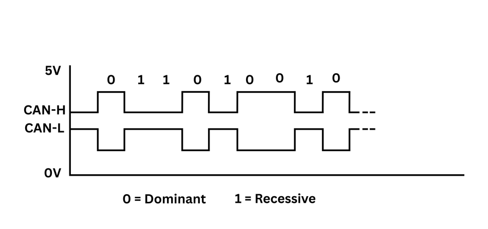
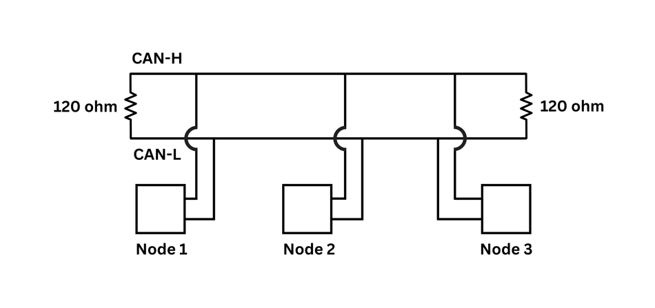
Wiring and Signaling: It uses a two-wire differential bus, with lines designated CAN-H (CAN High) and CAN-L (CAN Low). Data is transmitted using differential signaling, where the voltage difference between CAN-H and CAN-L represents the logic state. This provides excellent common-mode noise rejection, making it suitable for electrically noisy environments, such as automobiles.
Recessive State (Logic '1'): Both CAN-H and CAN-L are typically at approximately 2.5V, resulting in a differential voltage close to 0V.
Dominant State (Logic '0'): CAN-H is driven to approximately 3.5V and CAN-L to approximately 1.5V, creating a differential voltage of about 2V. [3]
Baud Rates: Supports bit rates up to 1 Mbit/s for Classical CAN. With CAN FD and appropriate transceivers (like CAN SIC transceivers), data phase bit rates can reach 5 Mbit/s or even 8 Mbit/s.
Termination: The bus must be terminated at both physical ends with 120Ω resistors connected between CAN-H and CAN-L. These resistors match the characteristic impedance of the twisted-pair cable, preventing signal reflections that can corrupt data and ensuring the bus returns to the recessive state.
Cable Length: Inversely related to baud rate. At 1 Mbit/s, typical lengths reach 40m; at 125 kbit/s, up to 500m, ensuring reliable communication among distant nodes.
ISO 11898-3: Low-Speed Fault-Tolerant CAN
Commonly referred to as “Low-Speed CAN” or “Fault-Tolerant CAN,” this layer is designed for applications where continued operation is needed despite wiring faults.
Wiring and Signaling: Uses a two-wire bus (CAN-H, CAN-L), but with a focus on fault tolerance.
Baud Rates: Supports speeds up to 125 kbit/s.
Termination: Unlike high-speed CAN, termination resistors are typically located at each node rather than just at the bus ends. Each node has a fraction of the total desired termination resistance (e.g., RTH/RTL).
Voltage Levels: Employs different, often larger, voltage swings compared to high-speed CAN to enhance noise immunity and fault tolerance. For example, in the recessive state, CAN-H might be pulled to 0V and CAN-L to 5V, while in the dominant state, CAN-H is driven towards the supply voltage (e.g., 5V) and CAN-L towards 0V.
SAE J2411: Single-Wire CAN (SWCAN)
The SAE J2411 standard defines a single-wire CAN implementation for low-bandwidth, cost-sensitive automotive applications.
Wiring: Uses a single signal wire plus a ground reference.
Baud Rates: Operates at a nominal 33.3 kbit/s, with high-speed modes up to ~100 kbit/s for ECU flashing or diagnostics.
Termination: Varies by implementation! For example, some ECUs include a built-in resistor (e.g., 9.09 kΩ) as specified in J2411.
Cable Length and Node Count: Max recommended length is ~60 meters; supports 2 to 32 nodes depending on electrical design.
Applications: Ideal for body control modules, mirrors, seats, or wiper systems—areas where performance demands are low but wiring reduction is crucial.
Understanding different CAN physical layers is essential for designing reliable and scalable automotive and industrial networks.
The Evolution: CAN FD and CAN XL
The original CAN protocol (now often termed Classical CAN) served automotive and industrial needs well for decades. However, the increasing complexity of vehicle electronics, the rise of ADAS, high-resolution sensors, and the data demands of EV powertrains and over-the-air (OTA) updates began to strain bandwidth and payload limitations of CAN.

This "arms race" between data demand and protocol capability necessitated the evolution of CAN.
1. CAN FD (Flexible Data Rate)
Introduced by Bosch in 2012 and standardized under ISO 11898-1:2015, CAN FD addresses two major limitations of Classical CAN: data rate and frame size. [4]
Flexible Bit Rate: CAN FD retains the nominal arbitration rate (up to 1 Mbit/s) for the initial part of the frame to maintain compatibility. However, the data phase can switch to higher speeds—commonly 5 Mbit/s or even 8 Mbit/s—allowing for faster data delivery.
Expanded Payload: Increases the data field from 8 bytes to up to 64 bytes, significantly improving transmission efficiency and reducing overhead in large message scenarios.
Key Frame Enhancements in CAN FD:
FDF (FD Format) Bit: Identifies a CAN FD frame (recessive in FD, dominant in Classic CAN).
BRS (Bit Rate Switch): Enables switching to the faster data rate.
ESI (Error State Indicator): Indicates whether the transmitter is in Error Active (dominant) or Passive (recessive) state.
DLC (Data Length Code): Still 4 bits, but extended to represent data lengths up to 64 bytes.
CRC: Uses a longer and more complex checksum—17-bit CRC for payloads ≤16 bytes, and 21-bit CRC for larger payloads.
While CAN FD offers vast performance improvements, it introduces compatibility challenges. Classical CAN nodes cannot interpret CAN FD frames and will flag them as errors. Therefore, transitioning to CAN FD requires gateways or full-network upgrades with FD-tolerant nodes.
2. CAN XL (eXtra Large)
CAN XL is the third-generation evolution designed to rival high-bandwidth networks like Automotive Ethernet while maintaining the robustness and low latency of CAN.
Higher Speeds: Targets data phase bit rates of up to 10–20 Mbit/s using advanced CAN SIC XL transceivers and optimized cabling. The arbitration phase remains at lower speeds (<1 Mbit/s).
Larger Payload: Supports up to 2048 bytes per frame, enabling transmission of bulk data such as sensor fusion output or even entire Ethernet frames without segmentation.
Architectural Innovations in CAN XL:
Separated Priority and Addressing: The 11-bit Priority ID governs bus access, while a new 32-bit Acceptance Field (AF) handles message filtering, allowing better routing flexibility.
SDT (Service Data Unit Type): Indicates the type of application-layer protocol or data (similar to EtherType in Ethernet).
VCID (Virtual CAN Network ID): Allows segmentation of up to 256 logical networks on a single physical CAN XL segment—critical for domain-based architectures.
Cascaded CRCs: Employs two checksums for better error detection—a 13-bit Preamble CRC (PCRC) and a 32-bit Frame CRC (FCRC)—together providing a Hamming distance of 6.
These innovations not only increase throughput but also enhance network determinism and security readiness, preparing CAN XL for next-generation vehicles and industrial systems.
3. CANsec: Built-in Data Link Layer Security
With increasing cybersecurity threats, CANsec adds a native security layer to CAN XL.
Purpose: Ensures authenticity, integrity, and confidentiality of messages—something absent in earlier CAN versions.
Cryptographic Tools: Uses AES-CMAC for integrity and AES-GCM for encryption, supporting 128- and 256-bit keys.
Performance: Designed for hardware implementation with minimal latency impact, enabling real-time secure communication.
SEC Bit: Indicates whether a frame is CANsec-protected; the protocol adds headers and trailers for authentication and encryption metadata.
The progression clearly shows CAN adapting to remain a relevant and powerful technology for in-vehicle networking, even as demands for data throughput and advanced features grow substantially.
Recommended Reading: Understanding CAN Bus: A Comprehensive Guide
Local Interconnect Network (LIN): The Cost-Effective Sub-Bus
While CAN addresses the need for robust, high-speed communication, many applications within a vehicle or industrial system involve simple sensors and actuators that do not require such high bandwidth or the associated cost.
For these scenarios, the Local Interconnect Network (LIN) was developed as a complementary, low-cost serial communication protocol.
Fundamental Concepts and Architecture
History and Evolution
The LIN protocol was conceived in the late 1990s by a consortium of automotive manufacturers (including BMW, Volkswagen, Audi Group, Volvo Cars, Mercedes-Benz) and technology providers (Motorola, Volcano Automotive Group). The primary motivation was to create a standardized, low-cost multiplex communication system for non-critical applications, such as comfort electronics, to reduce the cost and complexity associated with using CAN for every small sensor or actuator.
The LIN Consortium released several versions of the specification:
LIN 1.0 in 1999
LIN 1.1, 1.2, and 1.3 followed, with LIN 2.0 released in 2003 bringing significant enhancements.
LIN 2.1 was unveiled in 2006.
LIN 2.2A, the most widely used version currently, was released in 2010.
Eventually, the LIN specification was formalized as an international standard, ISO 17987 (released in parts starting in 2016), ensuring broader industry adoption and interoperability.
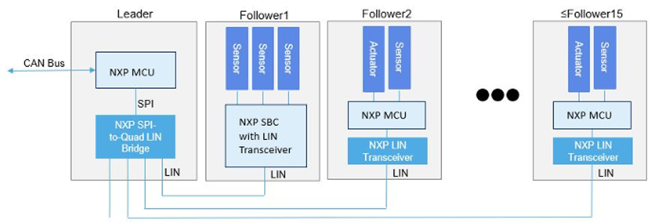
Master-Slave Architecture
LIN operates on a strict single-master, multiple-slave architecture.
A LIN cluster consists of one master node and up to 15 slave nodes (resulting in a maximum of 16 nodes per cluster).
The master node controls all communication on the bus. It initiates every message transmission by sending a "header."
A designated slave node (or sometimes the master node's own slave task) then responds to this header by sending a "response" containing the data.
This architecture eliminates the need for complex bus arbitration mechanisms found in multi-master systems like CAN, simplifying the protocol and reducing the cost of slave node implementation.
Single-Wire Communication
A defining characteristic of LIN is its use of a single wire for data communication, in addition to power (Vbat) and ground (GND) connections. This significantly reduces wiring harness complexity, weight, and cost compared to two-wire systems, such as CAN, making it ideal for cost-sensitive applications.
LIN Physical Layer Characteristics
The LIN physical layer is designed for simplicity and low cost:
Basis: It is based on the ISO 9141 standard (commonly known as K-Line), which was already established in automotive diagnostics. [5]
Voltage Levels: LIN typically operates with the vehicle's battery voltage (nominally 12V, but can range, e.g., 8V to 18V).
Recessive State (Logic '1'): The bus voltage is pulled close to the battery supply voltage (Vbat) by pull-up resistors. For receiving nodes, a bus level above approximately 60% of Vbat is typically interpreted as recessive.
Dominant State (Logic '0'): The bus voltage is pulled close to ground by an active transmitter. For receiving nodes, a bus level below approximately 40% of Vbat is typically interpreted as dominant. Transmitting nodes use stricter thresholds (e.g., >80% for recessive, <20% for dominant) to ensure sufficient noise margin.
Pull-up Resistors: The LIN bus requires pull-up resistors to maintain the recessive state when no node is transmitting. Typically, the master node has a stronger pull-up resistor (e.g., 1 kΩ), and each slave node has a weaker internal pull-up resistor (e.g., 30 kΩ). The master's stronger pull-up ensures the bus line is reliably pulled high.
Data Rate: LIN supports data rates up to 20 kbit/s. Common rates are 9.6 kbit/s, 10.4 kbit/s, and 19.2 kbit/s.
Implementation: The physical interface can often be implemented using a standard UART (Universal Asynchronous Receiver/Transmitter) peripheral found in most microcontrollers, coupled with a simple LIN transceiver IC. Slave devices can use internal RC oscillators, synchronizing via a synchronization byte in the frame header, eliminating the need for expensive crystal oscillators.
LIN Message Frame Format
All communication on the LIN bus occurs in frames. Each LIN frame is composed of two main parts: the Header and the Response.
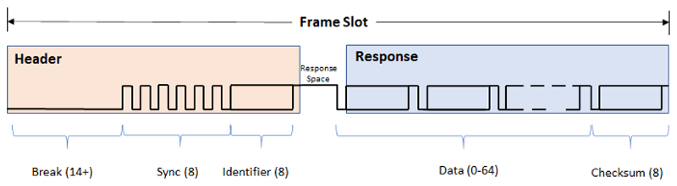
Header (Transmitted by Master):
Break Field (or Sync Break Field - SBF): This field signals the start of a new frame to all nodes on the bus. It consists of a sequence of at least 13 dominant bits, followed by a recessive Break Delimiter of at least one bit.
Sync Field (Synchronization Byte): An 8-bit field with a fixed pattern of 0x55 (binary 01010101) enable slaves to synchronize their internal baud rate using rising/falling edges.
Protected Identifier Field (PID): An 8-bit field that contains the actual 6-bit message Identifier (ID) and two parity bits (P0 and P1) for error detection on the ID itself. The ID Range Allocation (LIN 2.x):
IDs 0-59 (0x00 - 0x3B): Signal-carrying frames (data frames).
IDs 60 (0x3C) and 61 (0x3D): Diagnostic frames (Master Request and Slave Response, respectively).
IDs 62 (0x3E) and 63 (0x3F): Reserved for future enhancements or user-defined extensions.
Response (Transmitted by a designated Slave or Master's Slave Task):
Data Bytes: Contains the actual payload data, ranging from 1 to 8 bytes. The message ID implicitly defines the number of data bytes.
Checksum Byte: An 8-bit field used for error detection covering the data bytes (Classic Checksum) or data bytes plus PID (Enhanced Checksum).
Classic Checksum: Used for LIN 1.x compatibility and always for diagnostic frames (IDs 60, 61). Calculated over data bytes only.
Enhanced Checksum: Used for LIN 2.x frames. Calculated over data bytes and the Protected ID.
The simplicity of the LIN frame structure is a key enabler for the low-cost implementation of LIN nodes, as it obviates the need for precise crystal oscillators in slave devices.
LIN Scheduling and Frame Types
Communication in a LIN cluster is highly deterministic, orchestrated by the master node according to a predefined schedule.
Role of the LIN Description File (LDF)
The LIN Description File (LDF) is a critical configuration file that defines the entire behavior of a LIN cluster. It is an ASCII text file typically created by the network designer and contains information such as:
LIN protocol version and baud rate.
Node definitions (master and slaves, their capabilities).
Frame definitions (IDs, publishers, lengths, signals contained).
Signal definitions (names, sizes, encoding, initial values).
Schedule tables that dictate the sequence and timing of frame transmissions.
The master node executes one or more schedule tables defined in the LDF, which outline the sequence and timing of frame headers broadcast on the LIN bus. The LDF ensures synchronized operation and consistent interpretation across all connected nodes, contributing to the deterministic behavior of the protocol.
Frame Types in LDF Scheduling
The LDF defines how different types of frames are managed within the schedule tables:
- Unconditional Frames: These are the most common frame types. The master periodically sends a frame header, prompting a designated slave node (as defined in the LDF) to respond with the data field. Unconditional frames form the backbone of standard, cyclic communication in LIN networks.
- Event-Triggered Frames: Designed to optimize bus bandwidth, these frames enable multiple slave nodes to share a common frame ID. A slave node responds only if its data has changed. If two or more slaves respond simultaneously, a collision occurs, typically detected by the master via checksum errors. The master then resolves this using a predefined collision resolution schedule (often polling each slave using their unconditional frames).
- Sporadic Frames: These are master-published frames triggered only when the master detects a signal change in its own data. Because the master controls these transmissions, collision handling is not required. Sporadic frames reduce unnecessary bus traffic, improving efficiency when transmitting rarely updated data.
- Diagnostic Frames: Frames with IDs 60 (0x3C) and 61 (0x3D) are reserved for diagnostics - 0x3C: Master Request and 0x3D: Slave Response
These always carry 8 data bytes and support functions such as node configuration, fault diagnosis, and sleep control.
User-Defined and Reserved Frames:
1. ID 62 (0x3E): For user-defined or manufacturer-specific features
2. ID 63 (0x3F): Reserved for future protocol upgrades
The ability of LDF to define frame types and orchestrate them via schedule tables is critical to the low-cost, predictable behavior of LIN in embedded and automotive networks.
LIN Sleep and Wake-up Mechanisms
To conserve power, particularly in automotive applications where battery drain is a concern, LIN provides mechanisms for nodes to enter a low-power sleep state and subsequently wake up.
Entering Sleep Mode:
Go-to-Sleep Command: The master node can force all slave nodes into sleep mode by sending a specific diagnostic master request frame (ID=60 or 0x3C) with the first data byte equal to zero (and often remaining bytes set to 0xFF per LIN 2.1).
Bus Inactivity: Slave nodes will also automatically enter sleep mode if the LIN bus remains inactive for a specified period (e.g., more than 4 seconds according to LIN 2.x specifications).
Wake-up Mechanism:
Wake-up Request: Any node on the bus (master or slave) can initiate a wake-up request by forcing the bus line to a dominant state for a defined duration (e.g., 250 µs to 5 ms per LIN 2.x).
Node Readiness: Upon detecting a valid wake-up request, each slave node should become ready to process headers within a specified time (e.g., 100 ms).
Master Response: The master node should also detect the wake-up request and start sending frame headers when the slave nodes are expected to be ready (typically within 100-150 ms after receiving the wake-up request). The master can also wake the bus simply by starting to send a normal frame header (Break signal).
Wake-up Retries: If the master does not respond to the wake-up request of the slave within the specified timeframe, the slave may issue further wake-up requests with increasing delay intervals before subsequent attempts.
These mechanisms allow LIN clusters to minimize power consumption during periods of inactivity while ensuring timely reactivation when communication is required. Together with its minimal wiring requirements and simple physical layer, LIN remains a go-to solution for modern vehicle subsystems and embedded serial communication environments.
Hardware and Development Ecosystem
Both CAN and LIN are supported by a wide array of hardware components and a rich ecosystem of development tools, reflecting their maturity and widespread adoption.
CAN Hardware Components and Development Tools
Microcontrollers, Transceivers, and System Basis Chips (SBCs)
Microcontrollers (MCUs), DSCs, and MPUs: Most major semiconductor vendors offer MCUs with integrated CAN controllers, covering 8-bit, 16-bit, and 32-bit architectures. These are available for Classical CAN (2.0A/B), CAN FD, and increasingly for CAN XL. High-performance MPUs running RTOS or Linux often include multiple CAN channels and are ideal for automotive applications requiring advanced connectivity.
External CAN Controllers: For MCUs without built-in CAN, external controllers connect via SPI or parallel interfaces to provide CAN functionality. They are useful for adding additional CAN channels or expanding legacy systems.
CAN Transceivers: These interface the digital CAN controller with the differential physical layer of the CAN bus. The types include:
High-Speed CAN (ISO 11898-2)
CAN FD Transceivers (supporting up to 5–8 Mbit/s data rates)
CAN SIC (Signal Improvement Capability) Transceivers (enhancing waveform quality for complex or high-speed networks)
CAN XL SIC Transceivers (supporting bit rates beyond 10 Mbit/s, with features like PWM coding)
Low-Speed/Fault-Tolerant CAN (ISO 11898-3)
Single-Wire CAN (SAE J2411)
Some transceivers also offer galvanic isolation, partial networking (selective wake-up), and enhanced fault tolerance.
System Basis Chips (SBCs): These integrate CAN transceivers with voltage regulators, watchdog timers, and sometimes LIN transceivers, reducing board footprint and system complexity. SBCs are widely used in automotive ECUs and are typically AEC-Q100 qualified.
Development Tools: Analyzers, Simulators, and Software Libraries
A rich ecosystem of development tools supports CAN protocol implementation:
CAN Bus Analyzers: These tools allow real-time monitoring and analysis of CAN traffic. Popular options include PCAN-Explorer, CANinterpreter, SavvyCAN, and vendor-specific solutions like Microchip’s CAN BUS Analyzer Tool. Advanced oscilloscopes with CAN decoding also help debug physical layer issues.
Simulators: Used for modeling entire CAN networks or individual ECUs during development and validation.
Software Libraries and Stacks: Vendors and third parties provide CAN protocol stacks, drivers, and APIs compatible with various MCUs, RTOS, and operating systems. Tools often support DBC files and MF4 log formats for decoding and data analysis.
Configuration Tools: Applications like CANdb++ Editor are used to create and manage DBC files, defining CAN message IDs, signal structure, and interpretation logic.
LIN Hardware Components and Development Tools
Similar to CAN, LIN is well-supported by a range of hardware and software tools tailored to its specific characteristics.
Microcontrollers and Transceivers
MCUs for LIN: LIN is typically implemented using low-cost 8- or 16-bit microcontrollers with standard UART or SCI peripherals. Many MCUs feature LIN-enhanced UARTs capable of handling break detection, synchronization, and sleep/wake-up logic in hardware.
LIN Transceivers: These devices handle voltage level shifting, slew-rate control (for EMI compliance), and single-wire communication. Many also support wake-up detection and protection against short circuits. Notable examples include: Microchip MCP2021 and NXP TJA102x series
System Basis Chips (SBCs): Some SBCs combine LIN and CAN transceivers with power management features, ideal for mixed-network nodes in body electronics.
Development Tools: LDF Editors, IDEs, and Software Stacks
LDF Editors and Generators: The LIN Description File (LDF) is the cornerstone of LIN network configuration. Tools exist for editing, validating, and generating C-code drivers from LDF files. They define frame scheduling, signal mapping, and node roles.
LIN Analyzers and Simulators: Tools like SavvyCAN and LIN tools from Microchip and Vector allow monitoring, simulation, and injection of LIN traffic. They decode messages using the LDF and highlight timing or protocol errors for debugging.
IDEs and Software Stacks: Many MCU vendors provide integrated development environments (IDEs) with LIN protocol stacks. These software packages manage message framing, checksum handling, header generation, and slave response logic. Companies like Simma Software offer portable LIN stacks compatible with major MCU platforms.
The availability of comprehensive hardware and software tools for both CAN and LIN significantly aids engineers in designing, implementing, testing, and debugging networks based on these protocols.
Design and Debugging: Best Practices and Common Pitfalls
Effective implementation of CAN and LIN networks requires careful attention to design principles and a systematic approach to debugging. Understanding common pitfalls can save significant time and effort during development.
CAN Bus: Design Best Practices and Common Pitfalls
Design Best Practices Checklist
Proper Termination: For high-speed CAN (ISO 11898-2), place 120Ω resistors at each physical end of the main bus to suppress signal reflections. Avoid placing termination on stubs or branches, and ensure exactly two terminators are active—no more, no less.
Cable Type and Routing: Use twisted-pair cables for CAN-H and CAN-L. Maintain consistent impedance and avoid running parallel to high-voltage or high-frequency signal lines to reduce EMI and crosstalk.
Stub Length: Keep stub lengths (connections from nodes to the main trunk) short—ideally <30 cm. Longer stubs introduce reflections, degrading signal quality, especially at higher data rates (e.g., CAN FD).
Grounding and Shielding: Implement a solid ground reference across all nodes and, where required, use shielded cables to mitigate external interference. Ensure common mode chokes or capacitive coupling are used correctly for fault tolerance.
Power Supply Stability: Use proper decoupling capacitors near CAN transceivers and ensure clean Vcc rails to prevent glitches or data errors.
Bus Load Planning: Consider the number of nodes and their combined capacitive loading. Overloaded buses may fail at high speeds due to RC delays. Refer to transceiver datasheets for max bus capacitance.
CAN FD Considerations: Use CAN SIC or CAN FD-compliant transceivers for CAN FD networks, as legacy transceivers may not support the faster rise times and may distort waveforms at >1 Mbit/s.
Common Pitfalls
Incorrect Termination: Adding more than two terminators or missing one can cause reflections, intermittent errors, or total communication failure.
Mismatched Baud Rates: Setting different bit rates on CAN controllers across nodes results in loss of arbitration and error frames.
Improper Bit Timing: Misconfigured sample points or time segments in the controller can cause sampling errors, particularly in CAN FD.
Ignoring Fault States: Not monitoring for Error Passive or Bus Off states in software can lead to silent node failures.
Failure to Ground Unused Pins: Leaving RX or TX pins floating on unused CAN transceivers may result in phantom signals or bus instability.
LIN Bus: Design Best Practices and Common Pitfalls
Design Best Practices Checklist
Single-Wire Integrity: Use appropriate LIN transceivers that manage slew rate control, voltage thresholds, and wake-up functionality per ISO 17987.
Proper Pull-Up Configuration: Ensure the master node has a 1 kΩ pull-up resistor to Vbat on the LIN line. Slave nodes should have weaker pull-ups (typically 30 kΩ). This ensures proper dominant/recessive state detection.
Cable Selection and Routing: Use a single wire with proper shielding and minimal bends to reduce EMI susceptibility. Avoid running LIN lines near switching power supplies or noisy digital signals.
Stable Power Supply: LIN transceivers typically operate at 12V, and voltage fluctuations can impair communication. Ensure proper regulation and filtering at the power input.
UART Configuration: Set UART parameters correctly—matching baud rate, break detection, and sampling edge timing. Use LIN-enhanced UARTs if available.
Slave Clock Synchronization: Rely on the sync field for slaves without crystal oscillators. Validate synchronization accuracy with an oscilloscope if errors occur.
Common Pitfalls
Improper LDF Usage: Inconsistent or misconfigured LIN Description Files (LDFs) between development and runtime tools lead to frame misinterpretation or scheduling errors.
Collision Mismanagement: Event-triggered frames must be backed by proper collision resolution schedules. Ignoring this leads to bus lockups.
Bus Inactivity Misconfiguration: Slave nodes entering sleep mode too early—or failing to wake correctly—due to improper timeout values can create hard-to-trace failures.
Exceeding Node Limits: LIN supports a maximum of 16 nodes (1 master + 15 slaves). Adding more causes undefined behavior.
Incorrect Checksum Mode: Mixing classic checksum (LIN 1.x) with enhanced checksum (LIN 2.x) frames in the same cluster without distinction can cause checksum errors and dropped messages.
Debugging Tools and Strategies
Use Protocol Analyzers: Tools like PCAN-Explorer for CAN or LIN bus analyzers decode messages in real time and highlight errors, frame timings, and bus status.
Monitor Error Counters: Read and log TEC/REC values in CAN nodes to detect hidden network problems before nodes enter Bus Off state.
Oscilloscope Verification: Always validate physical signals—dominant/recessive transitions, waveform rise/fall times, and voltage levels—with a CAN decoding oscilloscope or logic analyzer.
Inject and Simulate: Use simulators to inject controlled traffic and simulate slave node responses to test schedule handling, error recovery, and diagnostic behavior.
Recommended Reading: Report: The Technology Behind ADAS and a Crash-Free Future
Conclusion
Both CAN and LIN serve critical yet distinct roles in automotive and industrial communication systems. CAN excels in high-speed, real-time, and fault-tolerant applications, making it ideal for safety-critical ECUs and powertrain control. LIN, with its simplicity and low cost, is optimized for non-critical, low-speed functions like body electronics. Understanding their architectures, physical layers, frame formats, and development ecosystems empowers engineers to design robust, efficient, and scalable embedded networks. By leveraging the strengths of each protocol in the appropriate context, developers can achieve an optimal balance of performance, cost, and reliability in complex distributed systems.
Frequently Asked Questions (FAQs)
Q. What is the main advantage of LIN communication?
LIN communication offers a lower-cost solution for non-critical control systems, making it ideal for automotive body electronics requiring simple serial communication.
Q. How fast is LIN communication in kbps?
LIN supports data rates up to 20 kbps, with typical speeds like 9.6 kbps and 19.2 kbps, suitable for low-speed control and signal transmission.
Q. What is the typical CAN bus speed in Mbps?
Classical CAN operates at 1 Mbps, while CAN FD and CAN XL support up to 8 and 20 Mbps, respectively, ideal for high-performance control systems.
Q. Why is error handling important in CAN and LIN?
Robust error handling ensures reliable control systems, maintaining communication integrity even in electrically noisy automotive or industrial environments.
References
[1] IEEE Explore. Deep Learning in the Fast Lane: A Survey on Advanced Intrusion Detection Systems for Intelligent Vehicle Networks [Cited 2025 June 16] Available at: Link
[2] ISO. ISO 17987-1:2016 - Local Interconnect Network (LIN) [Cited 2025 June 16] Available at: Link
[3] Altium. CAN-Bus: Introduction and History [Cited 2025 June 16] Available at: Link
[4] Wevolver. CAN FD: Revolutionizing Automotive and Industrial Communications [Cited 2025 June 16] Available at: Link
[5] Softing Automotive. K-Line - ISO 9141 - Access to ECUs in Completed Vehicles [Cited 2025 June 16] Available at: Link
in this article
1. Introduction2. In-Vehicle and Industrial Networking: The Genesis of CAN and LIN3. Controller Area Network (CAN): The Robust Backbone4. Local Interconnect Network (LIN): The Cost-Effective Sub-Bus5. Hardware and Development Ecosystem6. Design and Debugging: Best Practices and Common Pitfalls7. Conclusion8. Frequently Asked Questions (FAQs)9. References