Motor Control Design: End-to-End Methodology
This article presents an end-to-end motor control design methodology covering mechanical sizing, power electronics, sensor selection, real-time control algorithms, EMC, and functional safety for engineers building motor drives.

26 May, 2026. 14 minutes read
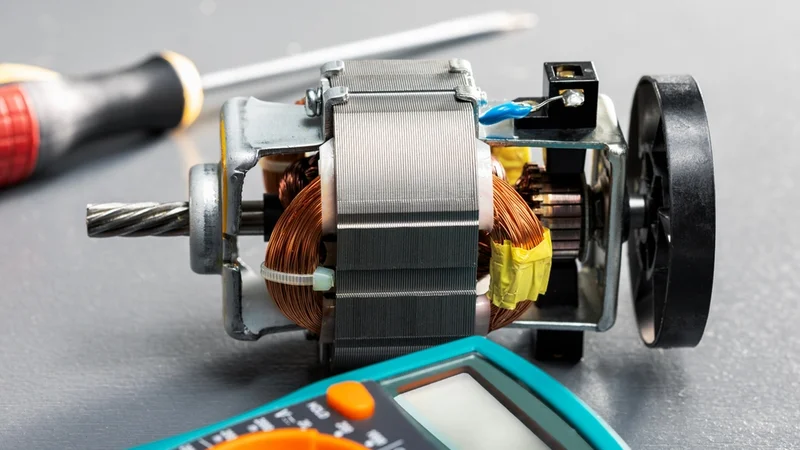
Exposed Electric Motor Assembly alongside Diagnostic Tools
Key Takeaways
Requirements Drive Everything: Define torque, speed, position precision, duty cycle, environment, EMC, and functional-safety targets before selecting a motor or control strategy.
Match Motor Type to the Application: DC motors offer simplicity; BLDC and PMSM provide high efficiency; induction motors handle robust industrial loads; steppers excel at open-loop positioning; servos combine high torque and precision.
Choose the Right Control Topology: Open-loop approaches suit simple applications; closed-loop field-oriented control (FOC), direct torque control (DTC), and model predictive control (MPC) provide high-performance torque and speed regulation.
Power Stage Design is Critical: Select MOSFETs, IGBTs, SiC, or GaN devices based on voltage and switching frequency; use isolated gate drivers like UCC21750 for high common-mode immunity; size DC-bus capacitors properly; add RC snubbers to damp ringing; compensate dead-time effects to minimise distortion.
Feedback Selection Influences Bandwidth: Hall sensors, incremental and absolute encoders, resolvers, or sensorless observers each offer unique resolution, robustness, and cost trade-offs; higher resolution improves accuracy but can limit loop bandwidth.
Compliance with Standards: Follow IEC 60034 duty types, IEC 61800 for adjustable-speed drives, IEC 61508 for functional safety, ISO 13849 for machinery safety, and ISO 26262 for automotive applications.
Introduction
The motor control design is a multidisciplinary process that connects motor physics, power electronics, embedded control, sensing, and system-level validation. Modern applications from robotics and industrial automation to electric vehicles and medical devices demand precise torque and speed control, high energy efficiency, low electromagnetic emissions, and functional safety.
The strong motor control design methodology begins with clear performance requirements. This is followed by motor selection, sensor strategy, inverter or driver architecture, control algorithm development, PCB layout, thermal planning, and EMC compliance. The effective motor control design ensures the complete drive system performs predictably, efficiently, and safely across its full operating range. This article presents an end-to-end motor control design approach for building robust, application-ready motor drive systems.
From System Requirements to Motor Control Architecture
Every successful motor drive begins with a clear definition of system requirements. Before selecting a motor, designing the inverter, or writing control firmware, engineers need to understand what the drive must achieve in the final application. This includes the required torque, speed range, duty cycle, acceleration profile, load inertia, operating voltage, environmental conditions, safety requirements, and communication interface.

For example, a robotic joint may require high torque density, low cogging torque, accurate position feedback, and smooth low-speed operation. The electric vehicle traction system, on the other hand, prioritizes high efficiency, wide speed range, regenerative braking, thermal robustness, and functional safety. Similarly, a fan or pump drive may be more focused on cost, acoustic noise, energy efficiency, and long service life.
These requirements shape the complete motor control architecture. They influence the motor type, power stage topology, sensor configuration, control algorithm, protection strategy, PCB layout, enclosure design, and software structure. If these decisions are made independently, the final drive may suffer from instability, overheating, poor efficiency, EMI failures, or limited operating range.
Recommended Reading: Motor Controller: Types, Design Considerations, Control Strategies, and Selection for Engineers
Requirements Analysis
Mechanical and Performance Requirements
Begin by quantifying the mechanical load. Then:
Required Torque is calculated from the mechanical load torque, including static friction, inertia, and external disturbances.
Required Speed (rpm or rad/s) must cover the entire operation range, including acceleration and deceleration.
Position Precision is defined by application needs.
The robotic joint may need 0.1° accuracy, while an industrial pump may require only speed regulation.
The dynamic response dictates how quickly a system must accelerate or reject disturbances. The servo bandwidth depends on mechanical inertia, friction, feedback sensor resolution, and the control loops in the drive. Higher inertia or friction reduces bandwidth. The current loop must have the highest bandwidth, followed by velocity and position loops, and encoders or resolvers in the control system influence precision.
Duty Cycle and Operating Environment
Duty cycle describes how a motor is loaded over time. IEC 60034-1 defines eight duty types. S1 indicates continuous operation at constant load until thermal equilibrium; S2 involves short-time duty with rest periods; S3 covers intermittent duty without starting effects; S4 and S5 include starting or braking with periods of rest or electric braking; S6 combines continuous operation with intermittent load; S7 adds electric braking to S6; S8 involves periodic duty with variable speed and load [1]. Selecting an appropriate duty type ensures the motor can withstand the thermal and mechanical stresses of the intended application.
Define environmental conditions: ambient temperature, humidity, vibration, dust, and altitude. They affect cooling, insulation ratings, and corrosion. High-temperature environments may require derating or special insulation classes. IEC 61800-3 categorises drives into classes C1–C4 according to voltage and environment; category C1 drives operate in domestic environments and must meet stricter emission limits, while C2–C4 apply to industrial installations [2].
Electromagnetic Compatibility and Functional Safety
EMC requirements ensure that the drive neither emits excessive electromagnetic interference nor is unduly affected by external noise. IEC 61800-3 references IEC 61000-4-x test standards and defines performance criteria A, B, and C for immunity tests [2].
The safety requirements depend on the application domain. IEC 61800-5-2 covers safety functions for adjustable-speed drives and works alongside IEC 61508, which defines safety integrity levels (SILs) based on hazard and risk analysis. IEC 61508 prescribes hazard and risk analysis to assign SIL 1–4 and mandates redundancy and diagnostics to achieve target SILs.
ISO 13849 defines performance levels (PL) and categories for machinery safety. ISO 26262 governs functional safety in road vehicles by defining Automotive Safety Integrity Levels (ASILs) and a lifecycle that spans planning, design, implementation, verification, validation, and production. Understanding which standards apply early in the process determines architectural decisions such as the need for redundant sensors, safe-torque-off (STO) channels, and certified microcontrollers.
Recommended Reading: BLDC Motor Controller: Comprehensive Design Guide for Engineers
Motor Selection and Sizing
Choosing the Motor Type
| Motor Type | Characteristics and Typical Uses |
| Brushed DC Motor | Simple control using PWM; suitable for low-cost speed control but requires maintenance of brushes and commutator |
| Brushless DC Motor | Uses electronic commutation; higher efficiency and longer life than brushed motors; good for fans, pumps, and e-bikes |
| Permanent - Magnet Synchronous Motor | High torque density and efficiency; typically driven by FOC; used in EVs and robotics |
| Induction Motor | Robust and economical; suited for industrial pumps, compressors, and HVAC; typically controlled using scalar V/f or vector control |
| Stepper Motor | Executes fixed step angles; useful for open-loop positioning; can stall at high load; commonly used in CNC, 3D printers, and robotics |
| Servo Motor | PMSM or BLDC with feedback and closed-loop control; delivers precise torque and position; used in robotics, CNC, and automation |
Torque-Speed Characteristics and Thermal Margin
Manufacturers provide torque-speed (T-N) curves showing continuous and peak torque regions. The continuous region (below the S1 line) indicates where the motor can operate continuously without overheating, while the intermittent region allows higher torque for limited periods. It is necessary to verify that the peak torque and speed of the application fall within these regions. Exceeding the continuous region requires additional cooling or a larger motor.
Thermal Margin is the difference between the rated temperature and expected operating temperature of the motor. Ensure adequate margin to handle ambient conditions and control system losses. The electric motors may require derating at high altitude or temperature.
Inertia Matching
The ratio of load inertia to motor inertia greatly influences control performance. Once the inertia ratio decreases, performance improves, and loop tuning becomes easier. The typical systems target ratios between 5:1 and 10:1, with 5:1 considered ideal for most applications. If the ratio is too high, acceleration and deceleration become sluggish; if too low, the motor may be oversized. Adjust inertia by selecting a different motor family or adding a gearbox.
Recommended Reading: Brushless vs Brushed Motor: Engineering Trade-offs and Design Decisions
Control Topology Selection
Open-Loop vs Closed-Loop Control
In open-loop control, the drive outputs a predefined voltage or current without feedback. This is adequate for constant-load applications such as stepper-motor positioning or fan speed control. Open-loop systems cannot reject disturbances, so closed-loop designs are preferred for precision.
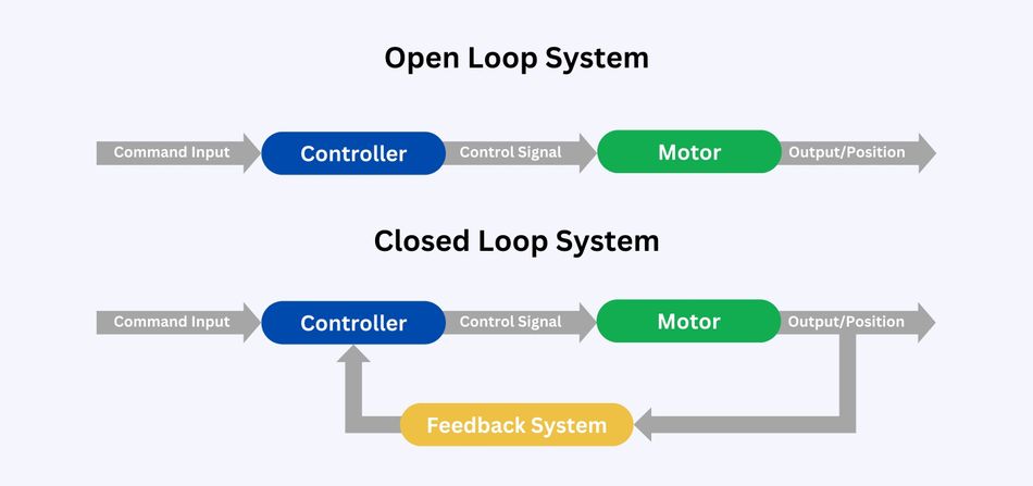
The closed-loop control uses sensors and algorithms to regulate current, torque, speed, and position. Control loop hierarchy is typically cascaded: an inner current loop regulates stator currents; a middle speed loop controls rotor speed; and an outer position loop (for servo systems) ensures accurate positioning. Each loop has progressively lower bandwidth to ensure stability.
Scalar Control (V/f)
Scalar or V/f control maintains a constant voltage-to-frequency ratio to keep magnetic flux constant in induction motors. It is simple and robust, but provides poor dynamic response because flux and torque are not decoupled. V/f is appropriate for pumps and fans where tight regulation is unnecessary.
Vector Control / Field-Oriented Control (FOC)
FOC transforms three-phase currents into two orthogonal components using Clarke and Park transformations. The Clarke transform converts the three-phase system into two stationary axes (α and β), and the Park transform rotates these into a rotating reference frame (d and q axes). This decouples torque (q-axis current) and flux (d-axis current), enabling independent control [3]. FOC provides fast torque response and low torque ripple and is widely used for PMSM and BLDC motors.
Direct Torque Control (DTC)
DTC directly regulates stator flux and torque without requiring coordinate transformations. It uses a switching table and hysteresis controllers to select inverter states that keep flux and torque within hysteresis bands. DTC offers very fast torque response and is robust to parameter variations but suffers from high torque ripple and variable switching frequency.
Model Predictive Control (MPC)
MPC predicts future states of the motor and inverter using a mathematical model and solves an optimization problem at each sampling period. MPC can handle multi-input, multi-output systems, include constraints and non-linearities, and provide better dynamic response and robustness compared to traditional PID control.
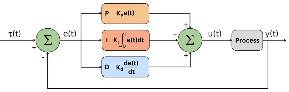
MPC has gained popularity for electric drives due to the availability of high-performance microcontrollers.
Sensorless Techniques
Sensorless control reduces hardware by estimating rotor position and speed from voltage and current measurements. The high-frequency injection injects a high-frequency voltage into the stator; the resulting current amplitude varies with rotor position due to saliency. This method suits interior-permanent-magnet motors. Back-EMF sliding-mode observer (SMO) estimates the back-EMF and deduces rotor speed from the back-EMF frequency. The technique is robust but performs poorly at low motor speed; the observer cannot estimate position at a standstill.
Recommended Reading: Stepper vs Servo Motors: Mastering Motor Selection for Precision Engineering
Power Stage Design
Semiconductor Selection: MOSFET vs IGBT vs SiC vs GaN
Silicon MOSFETs use unipolar conduction; they offer low on-resistance and fast switching, making them ideal for low-voltage (≤600 V) high-frequency applications. IGBTs handle high voltages (>600 V) and currents but have minority-carrier tail currents during turn-off, limiting switching frequency and causing higher losses [4].
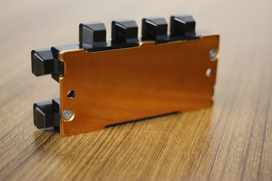
SiC MOSFETs are unipolar devices on a silicon carbide substrate; the wide bandgap provides higher critical electric field, superior thermal conductivity, and faster electron velocity, enabling high voltage operation, lower conduction and switching losses, and operation at junction temperatures above 175 °C. GaN FETs enable multi-MHz switching but target lower voltage ranges (~600 V) [2].
Gate Driver Selection and Isolation
Isolated drivers like UCC21750 provide reinforced isolation up to 5.7 kV, ±10 A peak gate drive, active Miller clamp, DESAT detection, and isolated analog sensing [2]. High common-mode transient immunity (CMTI) is essential when driving SiC or GaN devices to withstand high dv/dt edges.
Snubbers and Layout
Placing an RC snubber across the drain and source of each MOSFET dampens oscillations, reduces EMI, and protects against voltage overstress. Minimise loop area between the DC-bus capacitor and switching devices; place snubbers and gate drivers close to the devices. Use copper pours and ground planes to reduce stray inductance; use Kelvin-sense connections for current shunts.
Dead-Time and Dead-Time Compensation
Dead-time can be 0–5 µs depending on switch and gate driver; it introduces an average voltage error that increases with switching frequency, distorts the output voltage, and may cause harmonic distortion and control instability [5]. Dead-time compensation algorithms estimate the voltage error based on current polarity and adjust the commanded volt-second accordingly.
DC-Bus Capacitor Sizing and Regenerative Energy Management
Size the DC-bus capacitor to handle peak ripple current and voltage ripple (often <5 percent). In applications with regenerative braking, ensure there is a path to absorb returning energy: braking resistors, active front ends, or bidirectional converters.
Current Sensing
The shunt resistors offer high accuracy, low cost, and fast response but introduce insertion loss and require isolation amplifiers. Hall Effect sensors provide isolated measurement, low insertion loss, and can measure AC and DC currents, but have lower accuracy and slower response. Hall sensors suit high-current drives with galvanic isolation; shunts suit compact low-cost designs.
Recommended Reading: Why IGBTs Remain Relevant in the Era of SiC and GaN Power Devices?
Feedback Sensor Selection
Hall Sensors
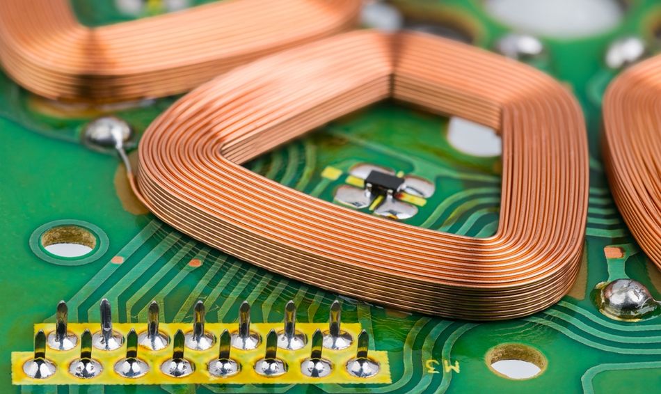
Hall effect sensors provide simple position feedback at discrete angles (typically every 60° electrical), sufficient for brushless DC motor commutation but not for high-precision control.
Incremental and Absolute Encoders
The incremental encoders output two quadrature pulse trains; if power is lost, absolute position is unknown. Similarly, absolute encoders output a unique code for each shaft position. Resolvers and encoders provide position and speed information; resolvers are robust and tolerate dust, moisture, shock and high temperature yet are bulky and lower resolution (~18 bits). On the other hand, encoders provide high resolution but are sensitive to contamination and loss of position on power loss.
Resolvers
Resolvers are analog rotary transformers producing sine and cosine voltages proportional to shaft angle. They provide absolute position, operate at temperatures above 125 °C, and are immune to dust and vibration. They have larger size, lower resolution, and lower speed capability (≤20,000 rpm). Resolvers are favoured in aerospace, heavy industry, and traction drives.
Sensorless Observers
SMO-based sensorless methods estimate back-EMF and derive speed; high-frequency injection uses magnetic anisotropy. Sensorless methods reduce cost but struggle at low speed.
Resolution vs Bandwidth Trade-Off
Higher encoder resolution improves position accuracy but increases data rates and may limit control bandwidth. Mechanical inertia, friction, motor type, and feedback mechanisms affect servo bandwidth [6].
Control Algorithm Implementation
Transformations and Observer Implementation
For field-oriented control, the algorithm starts by measuring the three-phase motor currents and converting them into a two-axis stationary reference frame using the Clarke transform. The Park transform then rotates these values into the d-q reference frame, where the controller can regulate the direct-axis current and quadrature-axis current independently. In most PMSM and BLDC systems, direct-axis current controls flux while quadrature-axis current controls torque. After current regulation, the inverse transforms convert the voltage commands back into three-phase PWM duty cycles for the inverter [5].
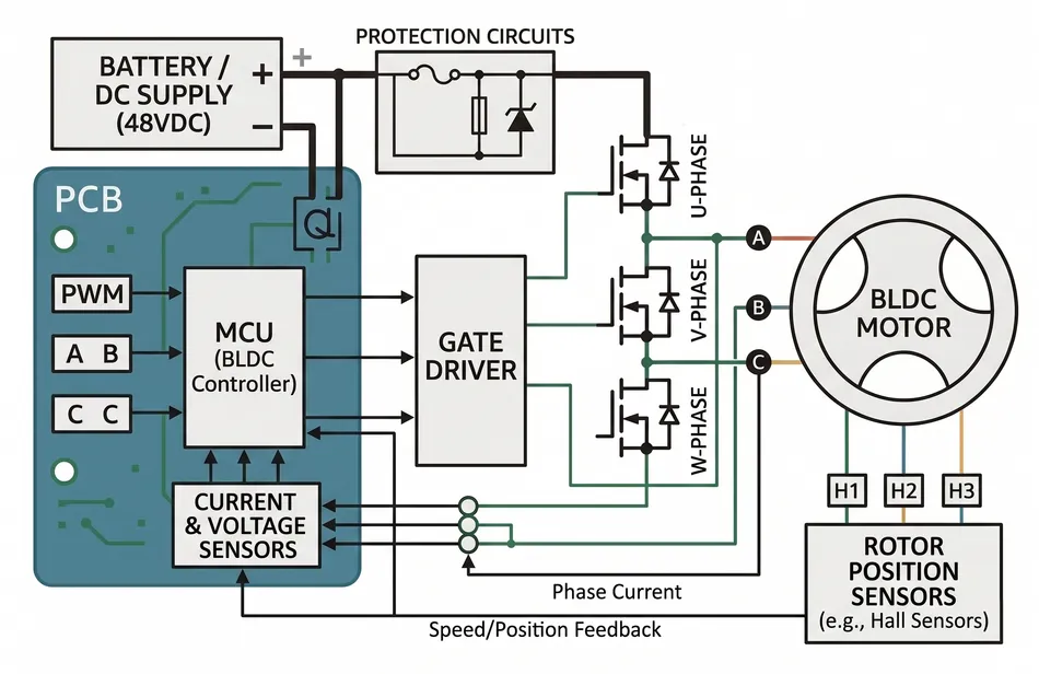
Once sensorless control is used, the controller must estimate rotor position without a physical position sensor. The sliding mode observer, or SMO, typically estimates motor current, compares it with measured current, processes the error through a switching function, and filters the result to extract back-EMF information. This estimated back-EMF is then used to calculate rotor position and speed. The observer must be tuned carefully because excessive filtering can slow the response, while insufficient filtering can introduce noise into the control loop.
PI Tuning and Anti-Windup
Tuning PI controllers begins with the current loop. Many FOC SDKs provide auto-tuning using recursive least squares (RLS) or model identification; smart control modules can identify PMSM parameters and tune PI controllers automatically. Add anti-windup mechanisms by limiting the integral term of the controller or using back-calculation. For speed loops, ensure the crossover frequency is an order of magnitude lower than the current loop.
Dead-Time Compensation and Feed-Forward
Include dead-time compensation by adjusting pulse-width modulation duty cycles based on current polarity and predicted voltage errors. Add feed-forward terms such as estimated back-EMF (sensorless FOC) or gravity and friction compensation (robotics) to improve dynamic response.
Microcontroller Selection
The microcontroller must provide enough processing performance, PWM resolution, ADC speed, communication support, and safety features for the selected control strategy. High-performance FOC requires fast current sampling, synchronized PWM updates, low-latency interrupt handling, and enough computation headroom for transformations, observers, protection logic, and communication tasks.
The common options include TI C2000 F28379D and F28004x devices for high-performance motor control, STM32 G4 and STM32 H7 series microcontrollers for cost-effective FOC implementations, and NXP MPC57 devices for automotive drive applications. For safety-critical systems, engineers should select MCUs that support IEC 61508 or ISO 26262 requirements, or use architectures with lock-step cores, hardware diagnostics, independent watchdogs, redundant sensing, and safe-state handling [2].
Recommended Reading: PID Controller & Loops: A Comprehensive Guide to Understanding and Implementation
Software Architecture
Control Loop Hierarchy and Timing
Motor control software typically executes a real-time interrupt (ISR) at the PWM frequency (10–100 kHz). The speed loop runs at 1–10 kHz, and the position loop (for servo systems) runs even slower. Current, velocity, and position loops form a cascaded hierarchy with decreasing bandwidths to maintain stability.
RTOS vs Bare-Metal
For simple drives, bare-metal firmware with interrupts and state machines suffices. Complex systems requiring task scheduling, communications, and diagnostics may benefit from an RTOS.
FOC Software Development Kits
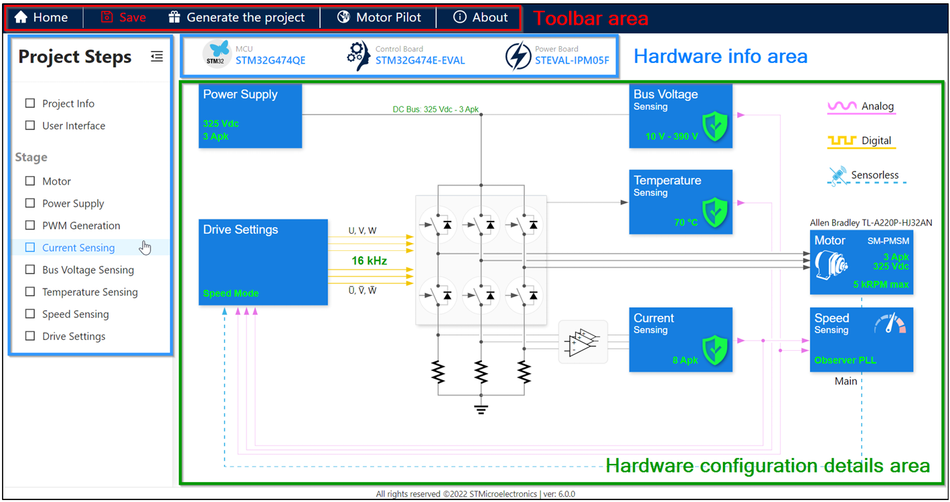
Examples include Motor Control SDK (MCSDK) by TI, X-CUBE-MCSDK by ST, Motor Control Application Toolbox (MCAT) by NXP, and open-source SimpleFOC. These SDKs include tuning tools, GUIs, and example projects.
EMC and Safety
Electromagnetic Compatibility Design
Implement proper filtering on the AC input or DC bus using common-mode chokes, X- and Y-capacitors, and EMI filters. Minimise loop areas, use shielded cables, and place the DC-bus capacitor close to the switching devices. Keep gate drive traces short and symmetrical and include series gate resistors to control dV/dt.
Isolation and Safety Standards
IEC 61800-5-1 defines requirements for isolation barriers, specifying clearance and creepage distances [2]. MCUs with diagnostic capabilities, redundant channels, and safe-torque-off outputs enable drives to meet SIL 2 or higher when used with properly designed safety circuits. IEC 61508 mandates hazard analysis, risk classification, and assignment of SIL levels; SIL 1–4 corresponds to increasing safety integrity requirements [4]. ISO 26262 adapts these concepts to road vehicles and defines ASIL A–D [3]. ISO 13849 introduces performance levels (PL a–e) for machinery. Integrate safety functions such as safe torque off (STO), safe brake control (SBC), safe limited speed (SLS), and safe direction (SDI).
Validation and Testing
Hardware-in-the-Loop and Simulation
Use motor modelling tools and simulate control algorithms to ensure stability, bandwidth, and robustness. HIL simulators such as Typhoon HIL and dSPACE emulate power electronics and motors in real time, allowing testing of embedded code under fault conditions without risk to hardware.
Dyno and System Testing
Perform laboratory testing on a dynamometer to measure torque, speed, and efficiency. Validate that the motor follows speed and position profiles accurately. Thermal characterization should measure winding and power device temperatures. For regenerative braking, verify that energy is safely dissipated.
EMC and Safety Testing
Conduct conducted and radiated emissions tests according to IEC 61000-3-2 and 61000-4-x. Apply ESD, fast transient, and surge tests to ensure immunity. Validate safety functions by injecting faults and verifying safe-torque-off operation.
Recommended Reading: EMI Shielding: Protecting Electronic Devices in a Noisy World
Common Pitfalls
Undersized DC-Bus Capacitors: Insufficient capacitance leads to large voltage ripple, torque ripple, and EMI.
Insufficient Phase Margin: Poorly tuned PI controllers can result in oscillations.
Current Sensor Offset Drift: Use auto-zero calibration and low-offset amplifiers.
Encoder Mounting Eccentricity: Use precision couplings, alignment tools, and calibrate the encoder index.
Dead-Time Distortion: Implement dead-time compensation [9].
Regenerative Braking Energy Handling: Provide braking resistors, active front ends, or energy storage.
Ignoring Standards Early: Integrate safety and EMC requirements into the architecture.
Conclusion
Effective motor control design demands a methodical approach that integrates mechanical sizing, electrical design, control theory, software architecture, safety, and EMC considerations. By performing detailed requirements analysis, selecting appropriate types of motor and control topologies, designing power stages with proper semiconductors, drivers, and sensors, and implementing well-tuned algorithms on suitable microcontrollers, engineers can build drives that deliver high efficiency, precision, and reliability. Following standards such as IEC 60034, IEC 61800, IEC 61508, and ISO 26262 ensures that designs meet regulatory requirements and protect users. Rigorous validation through simulation, HIL testing, and laboratory measurements verifies that the system performs as intended.
Frequently Asked Questions (FAQs)
Q. What is motor control design?
A. Motor control design is the process of selecting motors, sizing the power supply, designing control circuits, choosing sensors, and implementing algorithms that regulate torque, speed, and position in reliable motor control systems for real-world applications.
Q. How do you design a motor controller?
A. Start by defining torque, speed, duty cycle, environment, and precision positioning needs. Then select the motor, size the power stage, design control circuits, choose feedback sensors, implement the control method, and validate performance under expected operating conditions.
Q. What is FOC in motor control design?
A. Field-oriented control (FOC) is a vector-control technique that transforms three-phase currents into d-q components using Clarke and Park transformations. It is widely used in high-speed PMSM and BLDC drives requiring smooth torque and efficient operation.
Q. How do you choose a motor for a control system?
A. Choose a motor by matching torque, speed, inertia, duty cycle, and thermal limits to the application. Industrial applications may use AC induction motors, while actuators, robotics, and precision positioning systems often require servo or brushless motors.
Q. MOSFET vs IGBT for motor control: which should I choose?
A. MOSFETs suit low-voltage, high-speed switching and compact motor control systems, while IGBTs are preferred for higher-voltage industrial applications. The right choice depends on power supply voltage, current rating, switching frequency, efficiency, and thermal design.
Q. How do you validate motor control design?
A. The validation includes simulation, hardware-in-the-loop testing, dynamometer testing, thermal checks, EMC testing, and fault-response verification. Engineers confirm that the motor, armature behavior, control circuits, sensors, and software perform safely across operating conditions.
Q. What standards apply to motor control design?
A. Key standards include IEC 60034-1 for duty ratings, IEC 61800 for adjustable-speed drives, IEC 61508 for functional safety, ISO 13849 for machinery safety, and ISO 26262 for automotive motor control systems.
References
[1] ABB. Motor Guide: Duty Types S1–S8 [Cited 2026 May 24]; Available at: Link
[2] Texas Instruments. Functional Safety for Industrial Motor Drives [Cited 2026 May 24]; Available at: Link
[3] Microchip Technology. FOC Transformations User Guide: Clarke and Park [Cited 2026 May 24]; Available at: Link
[4] Wevolver. Why IGBTs Remain Relevant in the Era of SiC and GaN Power Devices? [Cited 2026 May 24]; Available at: Link
[5] NXP Semiconductors. Dead-Time Compensation Method for Vector-Controlled VSI Drives (AN4863) [Cited 2026 May 24]; Available at: Link
[6] Advanced Motion Controls. What is Servo Bandwidth: Definition, Formulas, Control Loops and Feedback [Cited 2026 May 24]; Available at: Link
in this article
1. Key Takeaways2. Introduction3. From System Requirements to Motor Control Architecture4. Requirements Analysis5. Motor Selection and Sizing6. Control Topology Selection7. Power Stage Design8. Feedback Sensor Selection9. Control Algorithm Implementation10. Software Architecture11. EMC and Safety12. Validation and Testing13. Common Pitfalls14. Conclusion15. Frequently Asked Questions (FAQs)16. References