What Is a PWM Signal? Fundamentals and Practical Applications for Engineers
A detailed exploration of PWM theory and practice: from duty cycle and frequency to motor control, LED dimming, and emerging market trends.

09 Sep, 2025. 12 minutes read
Key Takeaways
Pulse‑width modulation (PWM) toggles a digital output between two voltage levels, varying the duty cycle to change the average power delivered to a load.
Frequency and duty cycle jointly determine the output’s average and ripple; a higher frequency reduces perceptible flicker and allows smaller filters.
PWM can be generated by microcontrollers, 555 timers, or dedicated controllers; different PWM schemes (leading-edge, trailing-edge, center-aligned) address switching losses and filtering requirements.
Practical applications include LED dimming, servo positioning, DC motor speed control, DC‑DC conversion, audio amplifiers, and battery management.
The global microcontroller and PWM controller markets are growing rapidly, driven by applications in data centers, electric vehicles, IoT, and renewable energy.
Introduction
Modern electronic systems are dominated by digital logic, yet many real‑world devices—motors, lights, sensors and audio systems—require analog control. Pulse‑width modulation bridges this divide by using a digital waveform with a varying duty cycle to emulate analog levels. The technique rapidly switches a signal between high and low states and relies on the inertia of physical devices or a low-pass filter to smooth the switching into an average voltage. PWM is therefore fundamental to applications ranging from LED dimming and servo motor control to efficient DC‑DC converters and class‑D audio amplifiers.
With microcontrollers and field‑programmable gate arrays (FPGAs) providing programmable timers and dedicated PWM peripherals, engineers can implement high‑precision PWM with minimal hardware. However, understanding the mathematical relationship between duty cycle, frequency, and average output is crucial to designing robust systems that minimize ripple, switching losses, and electromagnetic interference. This article explains what is a PWM signal, explores different PWM techniques, and provides practical design guidance and market insights for engineers and engineering students.
Suggested Reading: FPGA vs Microcontroller Understanding the Key Differences and Use Cases
Understanding PWM Basics
Definition and Core Concepts
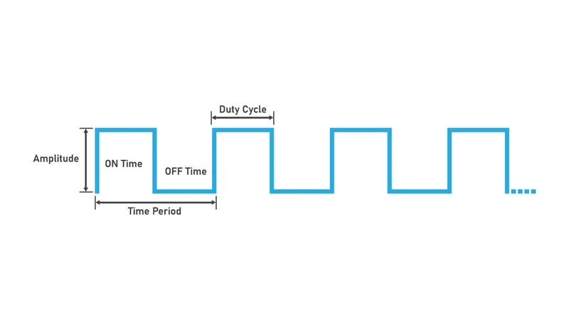
At its core, a pulse‑width modulation signal is a digital waveform that alternates between a high voltage Vhigh, and a low voltage Vlow. The period T of the waveform is the reciprocal of the frequency:

Within each period, the signal remains high for a duration ton and low for toff.

The duty cycle D is the fraction of the period during which the signal is high:

Adjusting D directly changes the average output voltage seen by a load. If the low level is ground, the average is simply:

Because the switching occurs quickly, inertial loads such as motors and the human eye integrate the waveform, perceiving a continuous level proportional to the duty cycle.

Duty Cycle and Average Voltage
The following figure illustrates PWM waveforms with duty cycles of 25 %, 50 % and 75 %. As the duty cycle increases, the high state lasts longer, increasing the average voltage delivered to the load. The relationship between duty cycle and average voltage is linear for a unipolar signal:
When D= 0%, the average is zero (always low)
When D= 100%, the average equals Vhigh.
The linearity makes PWM attractive for digital approximations of analog levels.
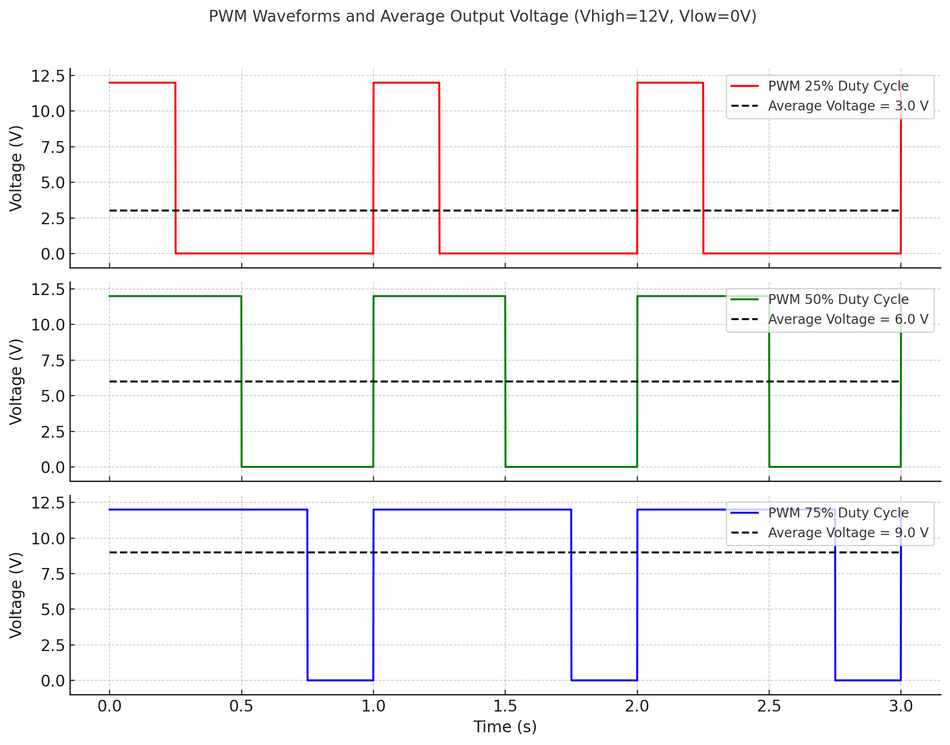
The average voltage of a PWM waveform with a high level of 12 V and a low level of 0 V varies linearly with duty cycle. Because the relationship is simple, microcontrollers can modulate the duty cycle to produce any intermediate voltage between 0 and 5 V. Higher duty cycles produce higher average voltages.
Frequency Considerations
The switching frequency of a PWM signal must be high enough that the load cannot follow individual transitions. For LED dimming, the human eye cannot perceive flicker above roughly 50–90 Hz. To ensure smooth brightness, designers typically use PWM frequencies of several hundred hertz or higher.
DC motors often use PWM frequencies from a few kilohertz up to tens of kilohertz to avoid audible whining and reduce torque ripple.
In servo motors, the frequency is conventionally around 50 Hz (20 ms period); the pulse width (typically 1–2 ms) encodes the position. Higher frequencies reduce output ripple and allow smaller filter components, but increase switching losses and electromagnetic interference.
Designers must therefore balance frequency, duty cycle resolution, and power dissipation.
Servo Control Example
Servo motors use PWM in a slightly different way than analog voltage control. Instead of varying the average voltage, the pulse width encodes the servo’s position.
A typical hobby servo interprets a 1 ms pulse as 0°, 1.5 ms as 90°, and 2 ms as 180°, with the repetition period around 20 ms (50 Hz). The following table summarizes common pulse widths and corresponding angles.
Note that this is a form of pulse‑position modulation within a constant‑frequency envelope; the average voltage is not the control parameter, but the timing of the pulse.
Pulse width (ms) | Approximate angle (°) | Duty cycle (%) at 20 ms period |
1.0 | 0 | 5 |
1.5 | 90 | 7.5 |
2.0 | 180 | 10 |
Mathematical Fundamentals of PWM
Average Value and Ripple
The average value of a PWM signal can be derived analytically. Let the high level be V1 and the low level be V0. Over a period T, the signal is high for ton and low for toff. The average (DC component) is:

If the low level is ground, this simplifies to:

In practice, the load does not see a perfect DC level but a waveform with ripple. When driving an inertial load (such as a motor or incandescent bulb), the mechanical or thermal time constant acts as a low‑pass filter. For purely electrical loads that require a smooth voltage, designers use RC or LC low‑pass filters to attenuate the switching frequency.
Analysis shows that increasing the duty cycle raises the average while simultaneously reducing ripple amplitude; increasing the filter time constant also reduces ripple. The ripple voltage is proportional to the amplitude of the fundamental and odd harmonics at multiples of the switching frequency.
Choosing a high switching frequency relative to the filter’s cutoff makes filtering easier but increases switching losses.
Fourier Series Perspective
A PWM waveform is a periodic rectangular pulse, and its spectrum contains a DC component plus harmonics at integer multiples of the fundamental frequency. The Fourier series representation is:

where:
Vk is the amplitude of the k-th harmonic
F is the fundamental frequency
Φk is the phase of the k-th harmonic
The amplitude of higher harmonics decreases with order. Because the harmonic content is concentrated at the switching frequency and its multiples, a simple low‑pass filter can recover the average value. Increasing f shifts harmonics further from DC, enabling better filtering. This spectral viewpoint highlights the trade‑off between switching frequency and filtering requirements.
Suggested Reading: Difference between Active and Passive Filters?
Duty Cycle Resolution
For the digital generation, the duty cycle resolution depends on the PWM counter width and the clock frequency. If a microcontroller’s timer counts up to N (e.g., 255 for an 8‑bit timer) each period, the smallest duty cycle step is 1/(N+1). Higher resolution requires wider counters or higher clock frequencies, both of which increase hardware complexity and power consumption.
For example, a 10‑bit PWM can generate duty cycles from 0 % to 100 % in 0.1 % increments, while a 16‑bit PWM provides much finer control at the cost of higher timer clock speeds. Designers must select a resolution that suits the application: LED dimming may only require 8 bits, whereas audio synthesis or precise motor control may demand 16 bits or more.
Generating PWM Signals
Microcontroller PWM Modules
Modern microcontrollers include dedicated PWM peripherals that generate duty‑cycle‑controlled waveforms autonomously once configured. A typical PWM module includes a counter, a comparator, and output logic. The counter increments each clock cycle and resets at a programmable top value. When the counter matches the comparator value, the output changes state.
Configuring the top value controls the period (and thus frequency), while the comparator value sets the duty cycle. By updating the comparator register, software can adjust the duty cycle in real time without CPU intervention. PWM modules often support different operating modes: edge‑aligned (leading or trailing), center‑aligned (where the output toggles on both counting up and down), complementary outputs with dead time (for half‑bridge drivers), and fault handling for over‑current protection.

The microcontroller market underscores the ubiquity of PWM: the global microcontroller market was valued at USD 32.37 billion in 2023 and is projected to reach USD 69.87 billion by 2030 with an 11.7 % compound annual growth rate (CAGR). This growth is driven by sectors such as automotive electronics, consumer devices, industrial automation and IoT, all of which rely on embedded PWM control for power regulation and actuation.
Generating PWM with a 555 Timer
Before microcontrollers became ubiquitous, engineers often used an NE555 timer in astable mode to generate PWM. In a basic configuration, the 555 switches a transistor that drives the load. By adjusting the ratio of resistors and a capacitor, one can control the charge and discharge times and thus the duty cycle.
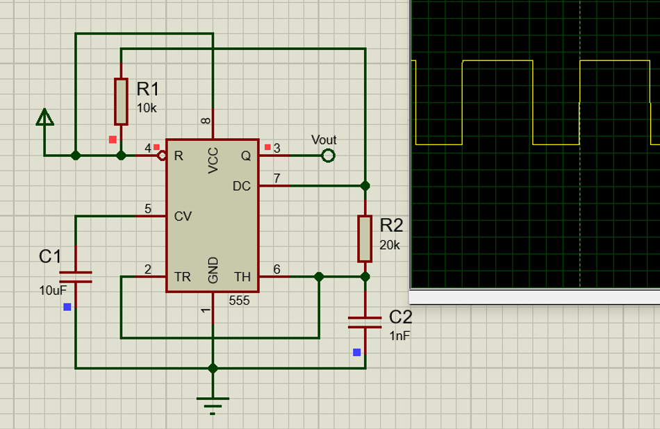
The following equations characterize the astable 555 circuit:

Time period for the wave is given by:

Varying R2 changes the duty cycle while keeping the frequency approximately constant. 555‑based PWM is still used in simple circuits and low‑cost motor controllers, but microcontrollers offer greater flexibility.
Software PWM
In systems lacking hardware PWM peripherals, engineers can implement software PWM by toggling a general‑purpose I/O pin at precise intervals using timer interrupts. This approach is flexible but consumes CPU cycles and may introduce jitter if interrupts are delayed.
Software PWM is practical for low‑frequency applications such as LED dimming or generating servo pulses but becomes challenging at high frequencies or when multiple channels are required.
Types of PWM Techniques
Pulse-width modulation can be implemented using various switching patterns to address specific applications or minimize switching losses. The following table summarizes common PWM types:
PWM type | Description | Common applications |
Single‑edge (leading‑edge or trailing‑edge) | Pulse starts (leading‑edge) or ends (trailing‑edge) at a fixed point in the period. The other edge moves with the duty cycle. Easy to implement, but concentrated switching transitions can induce electromagnetic interference (EMI). | Simple LED dimming, basic motor control |
Center‑aligned (symmetric or two‑edge modulation) | The PWM counter counts up and down; pulses are centered in the period with edges moving symmetrically. This distributes switching transitions and reduces harmonic content. | Motor drives, half‑bridge and full‑bridge converters |
Phase‑shifted PWM | Multiple PWM channels are phase‑shifted relative to each other to distribute current draw and reduce input ripple. | Multi‑phase DC‑DC converters, power factor correction |
Sinusoidal PWM (SPWM) | Duty cycle is modulated by a sinusoidal reference to approximate a sine wave. Used in variable‑frequency drives and inverters. | AC motor drives, uninterruptible power supplies |
Space‑vector PWM | A digital control method that selects inverter states to synthesize a desired voltage vector in a three‑phase system. Improves DC bus utilization and reduces switching losses. | Three‑phase motor control, industrial drives |
Hysteresis (bang‑bang) PWM | Switches when the output error crosses hysteresis thresholds. Self‑oscillating; frequency varies. | Switching regulators, temperature control |
Different PWM schemes impact switching losses, harmonic spectrum and control dynamics. Engineers select the method that best balances efficiency, complexity and performance for their application.
Practical Applications of PWM
LED Dimming
PWM is widely used to dim LEDs because their brightness is proportional to average current. A microcontroller toggles the LED rapidly between on and off states, and the human eye integrates this into a perceived brightness. Frequencies above 100 Hz avoid visible flicker.
Adjusting duty cycle changes brightness without altering the LED’s forward voltage, avoiding color shift and preserving efficiency. PWM also reduces thermal stress relative to linear regulators and is used in laptop backlights, smartphone screens and large video displays.
DC Motor Speed Control
A DC motor’s speed is proportional to the average voltage across its terminals. Driving the motor with a PWM signal provides a digitally controlled average voltage. Because the power transistor is either fully on or fully off, switching losses are low, and the controller is efficient.
In addition, PWM minimises motor heating compared with linear voltage control. For bi‑directional control, an H‑bridge or full‑bridge circuit uses complementary PWM signals to reverse current direction. Adjustable frequency can reduce audible noise and optimize torque ripple.
Suggested Reading: How Does a DC Motor Work? Unveiling the Power Behind Electric Motion
DC‑DC Conversion
Switch‑mode power supplies (SMPS) such as buck (step‑down), boost (step‑up) and buck–boost converters use PWM to regulate output voltage. A transistor (MOSFET) switches the input voltage on and off at high frequency; an inductor and a capacitor filter the output to produce a stable DC voltage.
Feedback adjusts the duty cycle to maintain regulation under varying load or input conditions. Class‑D audio amplifiers also use PWM to switch transistors at hundreds of kilohertz, filtering the output to drive speakers with high efficiency. PWM is fundamental to modern power electronics.
Battery Management and Other Applications
PWM appears in battery charging circuits, where it modulates current to prevent overheating and optimize charge profiles. It also controls power to solenoids, valves, and heaters, and is used in digital audio synthesis, telecommunications, and signal generation. In microcontroller‑based systems, PWM can generate analog voltages for sensors, generate audio tones, or control the dimming of displays. Its versatility makes it a key skill for engineers.
Suggested Reading: The pivotal role of battery management systems on the performance of electric vehicles
Advantages and Limitations
Advantages
Efficiency: Because the switching element is either fully on (low I2RI^2RI2R loss) or fully off (no current), PWM controllers have lower power dissipation than linear regulators.
Precise digital control: Microcontrollers adjust duty cycle numerically, enabling fine resolution and repeatable results.
Scalability: A single PWM module can control multiple loads; by using phase‑shifted PWM, designers can manage multi‑phase converters or drive multiple LEDs with reduced ripple.
Robustness: PWM is insensitive to variations in load impedance compared to analog voltage outputs.
Limitations
Switching losses and EMI: High switching frequency results in switching losses in transistors and potential electromagnetic interference. Careful layout, snubber circuits, and EMI shielding may be required.
Ripple and filtering: Without adequate filtering, the output contains ripple and harmonics that can affect sensitive loads. Designing low‑pass filters increases component count.
Finite resolution: Duty cycle resolution depends on timer resolution. Coarse resolution can cause quantization steps in analog outputs or audible stepping in LED dimming.
Dead time and cross conduction: Driving half‑bridges requires dead time between switching edges to prevent shoot‑through. Dead time distorts the effective duty cycle and complicates control.
Design Considerations and Implementation Tips
Select an appropriate frequency: Choose a switching frequency high enough to avoid flicker and reduce ripple, but not so high that switching losses dominate. LED dimming typically uses hundreds of hertz; DC motor control uses kilohertz; audio amplifiers operate at hundreds of kilohertz.
Ensure adequate resolution: Use timers with sufficient bit depth to achieve the desired granularity. For 8‑bit resolution, the maximum duty cycle error is 0.39 %; for 16‑bit it is 0.0015 %.
Use proper filtering: For analog outputs, design an RC or LC filter with a cutoff frequency well below the switching frequency. The filter’s time constant should be large relative to the PWM period to minimize ripple. Consider higher‑order filters for better attenuation.
Implement dead time: When controlling half‑bridge or full‑bridge circuits, insert dead time between switching edges to prevent shoot‑through. Many microcontrollers provide built‑in dead‑time generators.
Manage EMI: Layout the PCB to minimize loop area, use proper decoupling, and add snubber circuits or ferrite beads to reduce ringing and EMI.
Thermal considerations: Switching devices dissipate energy during transitions. Select MOSFETs or IGBTs with low switching losses and provide adequate heat sinking.
Feedback and control: In closed‑loop systems (e.g., voltage regulation), measure the output and adjust the duty cycle using proportional–integral–derivative (PID) controllers to maintain stability and response.
Conclusion
Pulse‑width modulation is a cornerstone technique in modern electronics, enabling digital systems to control analog quantities with high efficiency and precision. By switching a signal between high and low levels and adjusting the duty cycle, engineers can approximate any intermediate level, drive motors, dim LEDs, regulate power supplies and synthesize audio. This article has explained what is a PWM signal, analyzed its mathematical properties and spectrum, reviewed generation methods (hardware, 555 timer, software), compared PWM types, and explored numerous applications from motor control to power conversion. We have also highlighted design considerations such as frequency selection, resolution, filtering and EMI mitigation, along with market trends driving PWM innovation.
For digital design and hardware engineers, mastering PWM opens doors to efficient, flexible control solutions. As microcontrollers and power electronics evolve, PWM will remain a vital tool. Future developments in semiconductors, control algorithms and integration will push switching frequencies higher, reduce losses and expand PWM’s role in renewable energy, data centers and smart devices. By understanding the principles outlined here, engineers and students can confidently design and implement PWM systems that meet the demands of today and tomorrow.
FAQs
1. What is a PWM signal and how does it work?
A PWM (pulse‑width modulation) signal is a digital waveform that switches between high and low voltage levels with a fixed period. The proportion of time that the signal is high (the duty cycle) determines the average voltage delivered to the load. By varying the duty cycle, digital circuits can emulate analog voltages or currents.
2. Why is PWM preferred over analog voltage control in motor drives?
PWM allows the switching element (e.g., MOSFET) to operate fully on or fully off, minimizing power dissipation compared with linear regulation. It provides precise digital control and generates less heat, improving efficiency. In addition, PWM offers finer resolution and robust control over a wide range of motor speeds.
3. How do I choose the PWM frequency?
Choose a frequency high enough that the load cannot respond to individual pulses and ripple can be filtered effectively. LED dimming typically uses >100 Hz to avoid flicker, DC motors use several kilohertz to avoid audible noise, and audio amplifiers operate at hundreds of kilohertz. Higher frequencies increase switching losses and EMI, so balance these factors against filtering requirements.
4. Can PWM produce a true analog voltage?
PWM outputs are inherently digital, but the average voltage can approximate an analog level when filtered. Adding an RC or LC low‑pass filter attenuates the switching harmonics, producing a near‑DC voltage proportional to duty cycle. The quality of the analog output depends on filter design and switching frequency.
5. What are the differences between leading‑edge, trailing‑edge and center‑aligned PWM?
In leading‑edge PWM, the pulse starts at the beginning of the period and the trailing edge moves with duty cycle; trailing‑edge PWM keeps the end fixed and moves the leading edge. Center‑aligned PWM (also called two‑edge modulation) centers the pulse in the period, moving both edges symmetrically. Center‑aligned PWM distributes switching transitions, reducing harmonic content and switching losses.
6. How does servo motor control differ from standard PWM?
Hobby servos measure the width of pulses within a constant‑frequency frame. A 1 ms pulse corresponds to approximately 0°, 1.5 ms to 90°, and 2 ms to 180° when repeated every 20 ms. The duty cycle range is narrow (5–10 %), and it is the absolute pulse width—not the average voltage—that encodes position.
References
SNS Insider, “Home.” [Online]. Available: https://www.snsinsider.com.
SparkFun Electronics, “Learn.” [Online]. Available: https://learn.sparkfun.com.
GeeksforGeeks, “Home.” [Online]. Available: https://www.geeksforgeeks.org.
Swarthmore College, “LPSA: Linear Physical Systems Analysis.” [Online]. Available: https://lpsa.swarthmore.edu.
PlayEmbedded, “Home.” [Online]. Available: https://www.playembedded.org.
Electronics Tutorials, “Home.” [Online]. Available: https://www.electronics-tutorials.ws.
Grand View Research, “Home.” [Online]. Available: https://www.grandviewresearch.com.
Tenxer Labs, “Home.” [Online]. Available: https://www.tenxerlabs.com.
in this article
1. Key Takeaways2. Introduction3. Understanding PWM Basics4. Mathematical Fundamentals of PWM5. Generating PWM Signals6. Types of PWM Techniques7. Practical Applications of PWM8. Advantages and Limitations9. Design Considerations and Implementation Tips10. Conclusion11. FAQs12. References