BLDC Motor Controller: Comprehensive Design Guide for Engineers
This article details BLDC motor controllers, covering system roles, architectures, commutation methods, sensing techniques, power stages, protection, IC selection, application requirements and safety standards.

19 May, 2026. 17 minutes read
Key Takeaways
System Integration Matters – BLDC motor controller includes microcontroller firmware, gate drivers, a three-phase inverter, current/voltage sensing and protective circuits. Understanding how these pieces interact is critical when designing high-performance drives.
Commutation Strategy Affects Performance – Six-step/trapezoidal control is simple but noisy; sinusoidal control reduces ripple; field-oriented control (FOC) offers the highest efficiency at the cost of increased algorithmic complexity. Choosing the right method influences torque ripple, switching power loss and MCU load.
Sensing Topology Drives Cost and Precision – Low-side shunts are inexpensive but cannot detect ground faults. In-line phase sensing offers continuous measurement at the expense of higher common-mode requirements. Hall sensors provide reliable low-speed start-up, whereas sensorless back-EMF observers avoid additional wiring but struggle at low speeds.
Switching Devices Dictate Frequency and Efficiency – Silicon MOSFETs operate efficiently up to tens of kilohertz, while wide-bandgap GaN devices can switch an order of magnitude faster. Selecting SiC, GaN, or IGBT depends on bus voltage, power level and cost targets.
Application Requirements Vary Widely – Drones demand high switching frequencies (tested up to 60 kHz) to minimize torque ripple; e-bike traction controllers operate from 18 – 63 V and use FOC with 8 – 20 kHz PWM. HVAC blowers typically use 20 kHz trapezoidal drives; cordless power tools need compact 20 kHz inverters delivering hundreds of watts.
Compliance and Safety are Essential – Automotive designs follow ISO 26262 ASIL levels. Household appliances adhere to IEC 60730 classes, while efficiency standards like IEC 60034 define IE1–IE3 motor classes.
Introduction
Brushless DC motors (BLDCs) combine the efficiency of permanent magnets with the durability of electronic commutation. Their high power density, long life and low maintenance make them useful in drones, electric vehicles (EVs), HVAC systems, robotics and industrial pumps. BLDC motor controller, also called a brushless DC controller, motor drive or electronic speed controller (ESC), is the nervous system of these machines. It interprets command inputs, generates three-phase gate signals, measures currents and voltages, ensures safe operation and implements commutation algorithms.
Engineers rely on a BLDC Motor Controller to regulate speed, torque, and direction through advanced control algorithms such as PWM modulation, field-oriented control (FOC), and sensor-based or sensorless feedback mechanisms. This guide explores the fundamental principles, design trade-offs, and practical implementation strategies engineers need to develop high-performance BLDC motor control solutions.
What a BLDC Motor Controller Does?
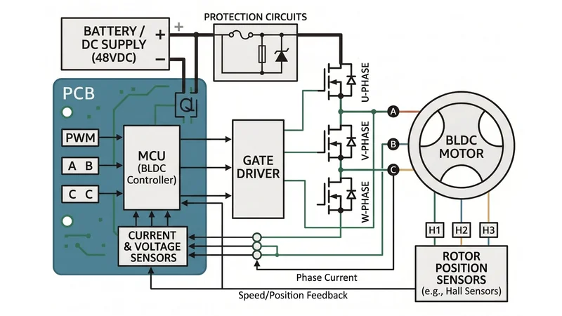
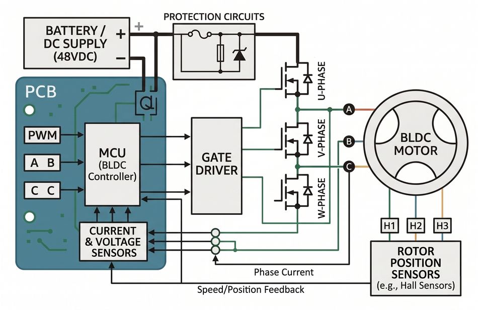
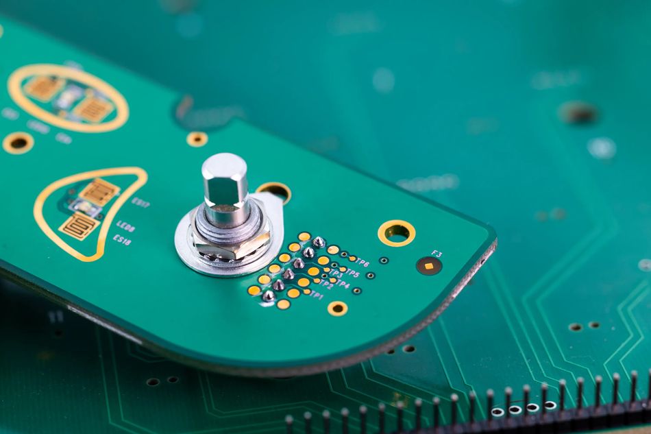
BLDC motor controller converts a DC bus into a three-phase AC waveform that synchronizes with the magnetic field of the rotor. The figure below shows the basic subsystems: a microcontroller or digital signal processor (DSP) executes control algorithms; a gate driver amplifies MCU logic signals to drive the MOSFET or IGBT power switches; the three-phase inverter modulates the DC bus into AC; sensors measure current, voltage and rotor position; protective circuits monitor for faults; and a power supply conditions the input voltage for logic and gate drive rails. [1]
The key functions include:
Generating Gate Signals – The controller synthesizes PWM waveforms to control the three high-side and three low-side switches of the inverter. Duty cycles are calculated to achieve the desired phase voltages or currents.
Commutation – The microcontroller determines the appropriate phase sequence based on rotor position. Trapezoidal control energizes two phases at a time; sinusoidal control continuously modulates all three phases; FOC transforms motor variables into a rotating reference frame and regulates torque and flux.
Current Regulation – Closed-loop control maintains current within desired limits to produce the commanded torque and protect the motor. FOC controllers implement separate D-axis (flux) and Q-axis (torque) loops.
Voltage Control and Power Management – The controller monitors the DC link and can modulate field weakening at high speeds to prevent voltage saturation.
Protection – Overcurrent, overvoltage, undervoltage, overtemperature and shoot-through faults must be detected quickly to prevent damage.
Communication – Interfaces such as PWM, UART, CAN, I2C or LIN connect the motor controller to the main system.
Recommended Reading: Brushless vs Brushed DC Motor: Engineering Trade-offs and Design Decisions
Architecture of a Brushless DC Motor Controller
Three-Phase Inverter Bridge
BLDC drive comprises a three-phase inverter. Six power switches (MOSFETs, IGBTs or GaN transistors) are arranged in a half-bridge configuration. Each pair connects one motor phase to the DC bus. Switching devices should have low RDS(on) or VCE(sat), fast switching speeds and appropriate voltage/current ratings.
Silicon MOSFETs dominate low- and mid-voltage applications up to ~100 V. IGBTs are used in high-voltage (>200 V) EV traction and HVAC compressors but switch more slowly (10–20 kHz). Wide-bandgap devices such as GaN and SiC offer higher breakdown fields (3.3–3.5 MV/cm) and bandgaps (3.26 – 3.39 eV) than silicon, enabling reduced conduction loss and switching at higher frequencies (tens to hundreds of kHz).
Microcontroller or DSP
The MCU performs signal processing, commutation calculation, loop control and fault handling. Fixed-function BLDC controllers such as the MC33035 integrate analog commutation logic but are limited to six-step control. Modern controllers use 32-bit MCUs or DSPs with dedicated motor control peripherals (PWM timers, ADC triggers, comparators) to support FOC. The processing requirement increases with algorithm complexity. For sensorless FOC at 60 kHz switching, a C2000 MCU running >60 MHz with floating-point support is typical. Integrated FOC drivers like MCF8316A embed the algorithm and current sensing, allowing code-free control at up to 75 kHz PWM. [2]
Gate Driver
Gate drivers translate MCU logic (3.3 V or 5 V) to the gate voltages required by MOSFETs or IGBTs (10–15 V). They also provide dead-time insertion to prevent simultaneous conduction of high- and low-side switches. For example, the DRV8323 gate driver offers adjustable dead times of 50 ns, 100 ns, 200 ns and 400 ns and supports supply voltages up to 60 V. Gate drivers may include charge pumps for 100% duty cycle operation, gate-drive current limiting, undervoltage lockout and fault diagnostics. Automotive drivers like the AMT49105 integrate a LIN interface and programmable dead time, operate from 5.5 – 50 V, and are ASIL A compliant.
Sensing and Feedback
Accurate sensing is required for closed-loop control and protection. Current sensors measure phase currents, typically using:
Low-Side Shunt Resistors – Placed between each inverter leg and ground, these sense resistors offer low cost and low common-mode voltage but cannot detect short-to-ground faults and only measure current when the low-side switch is on.
High-Side Shunts or Current Sense Amplifiers – Measure current in the supply line; they detect ground faults but require high common-mode capability and only measure current when the high-side device is on.
In-Line Phase Sensing – Uses a shunt or current sense amplifier in each phase. It measures current regardless of PWM state, enabling continuous sensing of drive, coast and brake modes. However, it requires amplifiers with high common-mode rejection and multiple channels.
Voltage sensing includes DC-link measurement and phase voltages for sensorless observers. Temperature sensors monitor the temperatures of the motor and power semiconductors.
Protection Circuits
Protection includes overcurrent detection (using comparators that trip above a set threshold), overvoltage and undervoltage lockout, temperature monitoring, shoot-through prevention via dead time, and gate-source clamps to limit voltage transients. Some designs incorporate over-miller clamp circuits to avoid dV/dt-induced gate turn-on. The MCF8316A integrates comprehensive protection including stall detection, anti-stall algorithm and overcurrent shutdown.
Recommended Reading: Microcontroller vs Microprocessor: A Comprehensive Guide to Their Differences and Applications
Commutation Methods
Commutation determines the sequence and shape of phase voltages. The choice of commutation strategy directly impacts torque quality, efficiency, acoustic noise, and computational requirements. The three common methods — trapezoidal (six-step), sinusoidal, and field-oriented control (FOC) represent increasing levels of control sophistication and performance.
Trapezoidal (Six-Step) Commutation
In six-step control each phase is driven with a rectangular voltage. Two phases conduct while the third is floating. The rotor position is sensed via Hall sensors or estimated from back-EMF zero crossings.
The advantages include simplicity, low computational load and minimal switching loss, making it suitable for cost-sensitive applications. However, large current steps generate torque ripple, audible noise and electromagnetic interference (EMI). Six-step drives cannot achieve constant torque at low speed because only two phases conduct.
Sinusoidal Commutation
Sinusoidal control drives the motor with three sinusoidal waveforms phase-shifted by 120°. This reduces harmonic content and torque ripple. Motor efficiency improves compared to trapezoidal drives, but all six switches operate at the PWM frequency, raising switching losses. Implementation requires microcontroller PWM generation and current sensing but is less complex than FOC. Sinusoidal control is popular in HVAC blowers where the key system specification calls for a 20 kHz inverter switching frequency to avoid audible noise and meet efficiency targets.
Field-Oriented Control (FOC)
FOC transforms three-phase currents into a rotating reference frame using Clarke and Park transforms. The Proportional-Integral (PI) controller regulates the d-axis current (flux) to zero and controls the q-axis current (torque). Inverse transforms convert control voltages back to three-phase modulation. FOC achieves optimal torque production and minimal torque ripple but demands high-bandwidth current sensing, position estimation and computational resources. Sensorless FOC is common in drones and EVs, using back-EMF observers or sliding-mode observers to estimate rotor angle. MCF8316A integrates sensorless FOC with dead-time compensation and current sensing, supporting up to 75 kHz PWM. In high-end drones, the FOC switching frequency is tested up to 60 kHz to reduce current and torque ripple.
Rotor Position Sensing
The accurate rotor position is essential for proper commutation. The controller must continuously align stator excitation with the rotor’s magnetic field; any phase error reduces efficiency and increases torque ripple. Rotor position sensing is broadly classified into sensored and sensorless approaches, each with distinct trade-offs in cost, complexity, and performance.
Sensored Methods
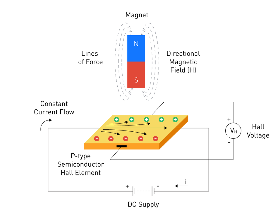
The Hall effect sensors or optical encoders provide discrete rotor position. Three Hall sensors placed 120° apart detect commutation points. Sensored systems enable reliable start-up and low-speed operation but add cost and complexity. Proper mounting and hysteresis compensation are required to minimize timing error. For precision servo drives, high-resolution encoders or resolvers deliver absolute position for FOC.
Sensorless Methods
Sensorless controllers infer rotor position from electrical measurements, reducing wiring and increasing reliability in harsh environments. The techniques include:
Back-EMF Zero Crossing – Detects the zero crossing of the undriven phase voltage relative to half of the DC bus. It is simple but fails at low motor speed because the back-EMF slope becomes small and noise/hysteresis degrade zero-cross detection. The improved detection technique extends sensorless operation down to 3 rpm by amplifying the back-EMF signal.
Flux Observer or Sliding-Mode Observer – Estimates rotor flux linkage using motor equations and measured currents/voltages. Observers provide better low-speed performance but require accurate motor parameters and high computational load.
High-Frequency Injection (HFI) – Injects a high-frequency voltage; the resulting electric current response depends on rotor saliency, enabling position detection at zero speed. HFI is used when start-up torque and zero-speed operation are critical.
Recommended Reading: How Does a DC Motor Work? Unveiling the Power Behind Electric Motion
PWM, Current Sensing and Control Loop
PWM Techniques
Pulse-width modulation controls the average voltage applied to each phase. The several modulation strategies exist:
Unipolar PWM (Six-Step) – Each phase is either connected to the DC bus or floats. Switching frequency is usually low (5–20 kHz) to minimize switching loss.
Bipolar PWM – Both high- and low-side switches are modulated, reducing common-mode voltage and EMI but doubling the number of transitions.
Sinusoidal PWM (SPWM) – Compares a sinusoidal reference with a carrier triangle to generate modulated duty cycles for each phase.
Space Vector PWM (SVPWM) – Uses space vector theory to synthesize the nearest active and zero vectors. SVPWM increases DC bus utilization by 15% compared to SPWM and reduces harmonic distortion.
The choice of switching frequency balances efficiency, EMI and acoustic noise. MOSFET-based drives typically switch at 20–50 kHz. The DRV8323 datasheet provides an example where, with an 8 V supply, the integrated charge pump supports a maximum PWM frequency of 45 kHz.
The wide-bandgap devices like GaN allow switching frequencies above 100 kHz, reducing filter size and torque ripple. High-speed drone ESCs operate at 60 kHz to reduce torque ripple and avoid interference with ultrasonic sensors. In contrast, e-bike traction controllers use 8 – 20 kHz PWM (16 kHz typical) to balance efficiency and acoustic noise. HVAC blower drives adopt 20 kHz switching to avoid audible whine.
Dead Time and Gate Drive Characteristics
Dead time prevents shoot-through by ensuring one device turns off before the complementary device turns on. Too much dead time reduces efficiency by causing body-diode conduction; too little risks cross-conduction. Adjustable gate drivers like the DRV8323 provide dead times of 50 ns to 400 ns. For SiC/GaN devices that switch faster, dead time may be reduced to tens of nanoseconds. Gate drive currents should be matched to MOSFET gate charge; high source and sink currents (1–2 A) are typical for <100 V MOSFETs. Automotive IGBT gate drivers often use 2.5 A sink and 1.75 A source currents. [3]
Current Sensing Topologies
Proper current measurement ensures torque regulation and protection. The Allegro current-sensing note summarizes the pros and cons:
Low-Side Shunts – Low cost and low common-mode voltage. Disadvantages: cannot detect short-to-ground faults; sensing occurs only when the low-side switch is on; requires synchronization with PWM.
High-Side Shunts – Can detect ground faults; require sensors with high common-mode voltage and only measure when the high-side is on. Not suitable for short-to-supply detection.
In-line Shunts – Provide continuous current measurement regardless of switching state, detect both short-to-ground and short-to-battery faults but need high common-mode tolerance and multiple amplifiers.
For high-accuracy drives, instrumentation amplifiers with percent-level gain error are used. For example, AN6320 sensorless electronic control design uses 1 mΩ shunts with 1% accuracy and an amplifier (TSC2020) with 0.3% gain error to measure currents up to 7.2A. In FOC, current must be sampled synchronously with PWM to avoid distortion.
Control Loop Design
Closed-loop control typically implements three layers:
Inner Current Loop – Regulates phase or D/Q currents using fast PI controllers. Sampling frequency equals the PWM frequency.
Speed Loop – Adjusts torque reference to reach the desired speed; bandwidth is 1/10 to 1/20 of the current loop.
Position Loop (if needed) – Controls rotor position using encoders, typical for servo drives.
Digital controllers must account for computation and ADC delays. FOC loops should complete calculations within each PWM period; integrated FOC drivers like the MCF8316A guarantee a speed loop accuracy of 3% using the internal oscillator and 1% with an external clock.
Recommended Reading: What Is a PWM Signal? Fundamentals and Practical Applications for Engineers
Power Stage Design
Device Selection
The choice of power switch depends on bus voltage, current, efficiency and cost:
Silicon MOSFETs – Dominant up to ~100 V. They offer low RDS(on) and are widely available. Switching frequencies up to 100 kHz are possible, but typical motor drives use tens of kilohertz to balance conduction and switching losses.
Silicon Carbide (SiC) MOSFETs – Support voltages up to 1,200 V and currents of hundreds of amps. The wide bandgap (3.26 eV) and high breakdown field (3.5 MV/cm) of SiC result in lower conduction and switching losses and enable high-temperature operation (600 °C). They are used in EV traction inverters delivering 50–200 kW, but at a higher cost. Switching frequencies are typically 20–50 kHz.
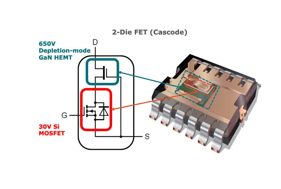
Gallium Nitride (GaN) FETs – Suitable for voltages up to ~650 V and power up to ~20 kW. GaN has a bandgap of 3.39 eV and can switch ten times faster than silicon, enabling 100 kHz or higher switching with low dead time. Ideal for drones, robotics and compact pumps where efficiency and size are paramount.
IGBTs – Preferred for high-power (>200 V) drives where conduction efficiency outweighs switching speed. IGBTs switch more slowly and are limited to ~20 kHz. They are used in automotive HVAC compressors and traction inverters.
Thermal and Layout Considerations
Efficient thermal design ensures reliable operation. Use copper pours and multiple vias for heat sinking; mount MOSFETs on heat sinks or metal substrate boards for high currents. The gate driver placement should minimize stray inductance. Kelvin connections to shunt resistors improve the accuracy of current measurements.
Passive Components
Gate Drive Supply – Provide stable gate bias, often using a bootstrap circuit or isolated DC–DC converter for high-side drivers.
Snubbers – R-C or R-C-D networks suppress voltage overshoot caused by device turn-off and parasitic inductances.
DC Link Capacitor – A low-ESR film or electrolytic capacitor stabilizes the bus and handles ripple current. Additional ceramic capacitors near the MOSFETs reduce high-frequency ringing.
Protection and Reliability
BLDC drives must protect both the motor and electronics:
Overcurrent and Short-Circuit Protection – Use comparators or overcurrent detection circuits that shut down the gate driver when current exceeds a threshold. Cycle-by-cycle current limiting is implemented in the TIDA-01353 blower design.
Overvoltage and Undervoltage Lockout – Prevent operation outside the safe bus voltage range. The MCF8316A includes undervoltage and overvoltage protection within its integrated regulator.
Overtemperature Protection – Monitors MOSFET or motor temperature using NTC or silicon sensors. In high-power drives, microcontrollers throttle current when the temperature rises.
Shoot-Through Prevention – Dead time and gate-driver logic prevent simultaneous conduction. The additional cross-conduction protection, such as Miller-clamp circuits, is available in automotive drivers.
dv/dt and EMI Control – Slew-rate control reduces electromagnetic emissions. The DRV8323 provides an adjustable gate driver slew rate to control dv/dt. Filters and shielding minimize EMI.
Recommended Reading: Why IGBTs Remain Relevant in the Era of SiC and GaN Power Devices?
Selecting a BLDC Motor Controller IC
Choosing a controller involves matching application requirements (voltage, current, commutation method, integration level) with available IC families.
Once selecting a controller, consider:
Voltage and Current Rating – Choose devices rated above the maximum bus voltage and peak current. For 48 V robotics or pumps, a 60 V driver suffices; EV traction may require 400 V-rated IGBT modules.
Integration Level – Integrated FOC drivers, such as MCF8316A, simplify firmware development but limit flexibility. Discrete gate drivers, along with MCUs, enable custom algorithms at the expense of development time. [5]
Sensorless vs Sensored – Sensorless controllers reduce wiring but may struggle at low speed. Hall sensors or encoders provide deterministic start-up and precise position control.
Protection and Safety – Automotive applications demand ASIL compliance. Appliances require compliance with IEC 60730.
Recommended Reading: Motor Controller: Types, Design Considerations, Control Strategies, and Selection for Engineers
Application Examples
Drones and UAVs
High-speed drone motors have low inductance and require high switching frequencies to reduce current ripple. TIDA-00916 reference design for drone ESCs uses sensorless FOC and reports testing up to 60 kHz PWM, which reduces torque ripple for low-inductance, high-speed motors and avoids interference with ultrasonic sensors. The design runs on two to six LiPo cells (approx. 6–25 V), achieves 12,000 rpm with a 6-pole-pair motor, and provides fast speed reversal for agile flight. Drones require high dynamic range; control loops must respond within ~0.2s to changes in thrust. Sensorless FOC is preferred due to weight and reliability constraints; high-frequency injection may be used to detect rotor position during start-up.
E-Bike and Light EV Traction
AN5709 e-Bike traction controller drives BLDC/PMSM motors up to 1 kW peak power and 60 A peak current, using a dsPIC33CK MCU and MIC4604 gate drivers. [4] It operates from 18 V to 63 V to support up to 15-series Li-ion batteries.
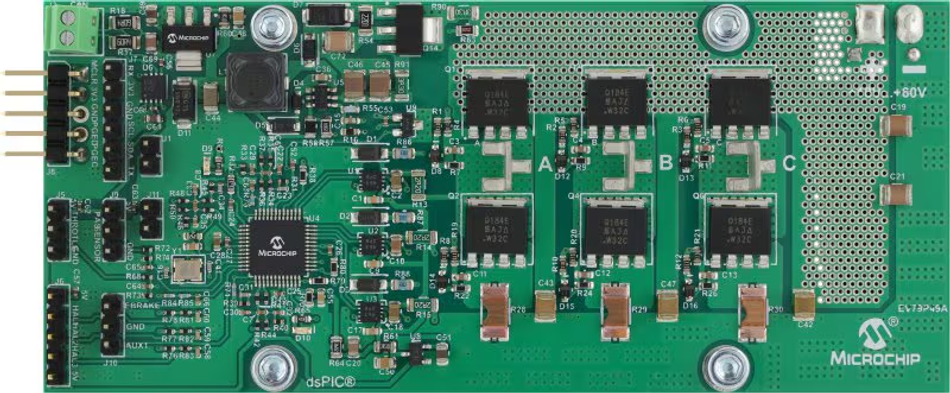
The design employs FOC for maximum efficiency and offers sensorless current feedback or Hall sensors. PWM switching frequency ranges from 8 kHz to 20 kHz, with a typical 16 kHz, balancing efficiency, motor heating, and audible noise. E-bike controllers often include regenerative braking and CAN or UART communication for integration with battery management and display units.
HVAC Compressors and Blowers
Automotive HVAC compressors operate from a high-voltage DC bus (up to 450 V). The TIDA-01418 reference design uses an IGBT inverter with InstaSPIN FOC control and lists a rated power of 4 kW and a maximum load current of 12 A. The design uses sensorless torque control and isolates CAN communication. HVAC blower motors in residential systems are smaller (≤375 W). The TIDA-01353 ECM blower design drives a ½ HP motor using sensorless trapezoidal control. Its key system specification shows a 20 kHz inverter switching frequency to minimize acoustic noise and meet efficiency requirements. The DC link is about 163.5 V DC from rectified 115 V AC. Such blowers prioritize low cost and reliability; integrated drivers with single-shunt sensing and optocoupler isolation are common.
Cordless Power Tools and Industrial Pumps
Cordless power tools and many industrial pumps share similar requirements: high torque, compact size and high efficiency. 18-V, 600-W BLDC inverter reference design for cordless tools operates from 5–21 V and delivers 33 A RMS continuous current at a 20 kHz switching frequency. It uses sensor-based trapezoidal control for robustness and includes protections against overcurrent and shoot-through. For pumps requiring smoother torque and quieter operation, sensorless or sensored FOC at 15 – 25 kHz is typical. The wide-bandgap devices enable higher switching frequencies, reducing passive component size and improving efficiency.
Robotics and Mechatronics
Robotic actuators demand precise torque and position control across a wide speed range. Drives typically operate at 24–48 V and supply tens of amps. While few publicly available documents provide explicit switching frequency figures, robotics drives generally use FOC with 20–50 kHz PWM to reduce cogging and audible noise. Hall sensors or high-resolution encoders provide absolute position feedback. Torque loop bandwidths on the order of 1 kHz enable compliant interaction in cobots. Integration with EtherCAT or CANopen is common for multi-axis coordination.
Industrial Pumps and Fans
Industrial pumps and fans often require sensorless control to minimize wiring and cost. For example, an integrated driver like A89306 supports 5.5 – 50 V supplies and sensorless FOC with quiet operation. In such systems, switching frequencies around 20 kHz ensure low audible noise and manageable switching loss. Pumps handling fluids may operate continuously; thermal management and conformal coating protect against moisture. Efficiency standards may drive the adoption of IE2 or IE3 motors, according to IEC 60034.
Standards and Functional Safety
ISO 26262
ISO 26262 addresses the functional safety of automotive electrical and electronic systems. It defines Automotive Safety Integrity Levels (ASIL A–D), which require hazard analysis, fault tree analysis, redundancy, and rigorous verification. Motor controllers used in electric power steering, traction drives, or HVAC compressors must meet ASIL requirements. Designers use safety-certified microcontrollers with diagnostic features, dual-core lockstep and built-in self-tests. Hardware design includes redundancy, protection against extreme temperatures and vibrations, and fail-safe operation.
IEC 60730 and Appliance Safety
IEC 60730 classifies software into Classes A (no safety implications), B (prevents hazards when control fails) and C (control continues to prevent hazards without external devices). Household appliances such as washing machines, dishwashers, and HVAC blowers use BLDC drives that must comply with Class B or Class C, depending on whether external protective devices are present. Compliance requires self-test routines, watchdog timers and robust error handling. [6]
IEC 60034 and Efficiency Classes
IEC 60034 defines performance characteristics and energy efficiency classes for rotating electrical machines. Efficiency classes include IE1 (standard), IE2 (high efficiency), IE3 (premium efficiency) and IE4 (super premium). Regulations in Europe mandate IE2 motors from 2011 and IE3 for larger motors from 2015 onward. Though BLDC motors are inherently efficient, selecting motors certified to the appropriate IEC class ensures compliance with regional energy regulations.
Other Standards
Other relevant standards include IEC 61800-5-1 for adjustable-speed electrical power drive systems, UL 1004 for electric motor certification, and the ISO 17987 (LIN) and ISO 11898 (CAN) communication standards. For industrial pumps in hazardous locations, IEC 60079 addresses intrinsic safety. Engineers must consult domain-specific regulations for certification.
Conclusion
BLDC motor controllers are the foundation of modern electromechanical systems, spanning drone ESCs, e-bike traction drives, HVAC compressors, robotics, pumps and power tools. Designing a controller demands a careful balance among commutation strategy, sensing topology, power-stage technology, switching frequency, and protection. Six-step control suits low-cost applications but sacrifices smoothness; sinusoidal and FOC improve efficiency and torque quality at the expense of complexity and switching losses. Accurate current and position sensing underpin performance, with low-side shunts offering economy and in-line sensing enabling continuous control. Wide-bandgap devices enable higher switching frequencies and compact designs.
Future trends point to increased integration of FOC algorithms, self-tuning and diagnostic features as seen in the MCF8316A, adoption of GaN and SiC devices for efficiency gains, predictive thermal monitoring leveraging embedded sensors, and AI-based commutation that optimizes torque per watt across changing conditions. Engineers who master these concepts will design drives that are not only efficient and reliable but also adaptable to the evolving demands of electrified mobility and automation.
Frequently Asked Questions (FAQs)
Q. How does a BLDC motor controller work?
A. BLDC motor controller converts DC power into controlled three-phase signals that synchronize with the rotor’s magnetic field. It uses PWM switching, rotor position feedback, and current sensing to regulate speed, torque, efficiency, and protection against faults such as overcurrent or overheating.
Q. What is the difference between trapezoidal and FOC control?
A. Trapezoidal control energizes two windings at a time using simple switching, producing higher torque ripple and noise. FOC continuously regulates magnetic fields for smoother operation, higher efficiency, and better performance in synchronous motors, robotics, and precision motion-control motor types.
Q. Sensored vs sensorless: which should I choose?
A. Sensored systems use Hall sensors or encoders for accurate low-speed control and reliable startup. Sensorless systems estimate rotor position electrically, reducing wiring and cost. Sensorless control is ideal for fans and drones, while sensored drives suit robotics, servo systems, and precision motion control applications.
Q. What microcontroller do I need for FOC?
A. FOC requires a 32-bit MCU or DSP capable of high-speed mathematical processing, ADC sampling, and PWM generation. Controllers for advanced motor types typically include dedicated peripherals for current sensing, trigonometric calculations, and real-time control of synchronous motors and high-efficiency inverter systems.
Q. How do I choose a switching frequency?
A. Switching frequency affects efficiency, EMI, thermal performance, and acoustic noise. Higher frequencies reduce current ripple in motor windings and improve smoothness but increase switching losses. The optimal value depends on motor types, inverter topology, cooling capability, and desired control bandwidth.
Q. What is dead time and why does it matter?
A. Dead time is a small delay inserted between switching transitions in a half-bridge inverter to prevent shoot-through currents. Excessive dead time reduces efficiency and distorts current waveforms, while insufficient dead time can damage power devices through simultaneous high-side and low-side conduction.
Q. How do standards like ISO 26262 and IEC 60730 affect motor controller design?
A. These standards define safety, diagnostics, and fault-handling requirements for motor controllers used in automotive and industrial systems. Designers must implement watchdogs, protection logic, safe shutdown states, and validated connector interfaces to ensure reliable operation and extended system lifespan under fault conditions.
References
[1] Texas Instruments. Brushless-DC Motor Driver Considerations and Selection Guide [Cited 2026 May 4]; Available at: Link
[2] Allegro MicroSystems. Current Sensing in Brushless Motor Drives (AN296276) [Cited 2026 May 4]; Available at: Link
[3] Wevolver. Powering Electric Motor Drives: Si, SiC, and GaN Devices [Cited 2026 May 4]; Available at: Link
[4] Microchip Technology. AN5709: e-Bike Traction Motor Control Reference Design [Cited 2026 May 4]; Available at: Link
[5] US Department of Energy. Premium Efficiency Motor Selection and Application Guide [Cited 2026 May 4]; Available at: Link
[6] Texas Instruments. Automotive HVAC Compressor Reference Design with InstaSPIN-FOC [Cited 2026 May 4]; Available at: Link