Potentiometer Schematic: Theory, Types, and Practical Implementations for Engineers
This technical article explains the theory behind potentiometer schematics. It shows how to implement mechanical and digital potentiometers in practical circuits, tailored for engineers, and students.

24 Nov, 2025. 15 minutes read
Key Takeaways
Potentiometer is a three‑terminal variable resistor that divides voltage or current by moving a wiper along a resistive element. In a schematic, it is drawn as a resistor with an arrow or diagonal line representing the wiper.
The resistive element may be carbon composition, wire‑wound, conductive plastic, or cermet, each offering different power ratings, precision, and lifespan.
Rotary, linear/slide, trimmer, and digital potentiometers offer various form factors and control methods. Logarithmic (audio) tapers are preferred for audio control, while linear tapers are suitable for general signal trimming.
Digital potentiometers are integrated circuits that emulate a using resistor ladders and MOS (Metal-Oxide-Semiconductor) switches; they accept SPI or I²C commands and offer resolutions ranging from 32 to over 1,000 steps.
Correct wiring ensures predictable behavior; using two pins creates a rheostat (variable resistor), while three-wire wiring yields a voltage divider. Motorized and multi-gang pots enable remote or multi-channel control, while digital pots simplify programmable gain and calibration tasks.
Introduction
The potentiometer schematic is a fundamental representation used to illustrate how a potentiometer functions within an electrical or electronic circuit. Engineers rely on a potentiometer schematic to understand variable resistance control, voltage division, and signal tuning applications. This schematic typically depicts a three-terminal resistor with an adjustable wiper, enabling precise control over voltage or current flow.
In modern electronics, a potentiometer schematic plays a crucial role in designing volume controls, sensor calibration systems, and motor controllers. Understanding the potentiometer schematic allows engineers to analyze circuit behavior, ensure accurate signal adjustments, and optimize component integration in both analog and digital systems. This article explores the theory, classifications, and practical implementations that guide effective engineering decisions using potentiometer schematics.
Fundamentals of Potentiometer Schematics
Definition and Operation
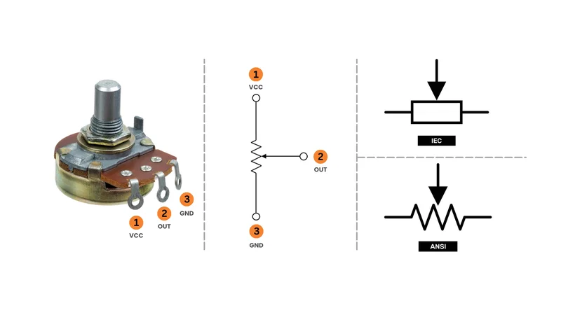
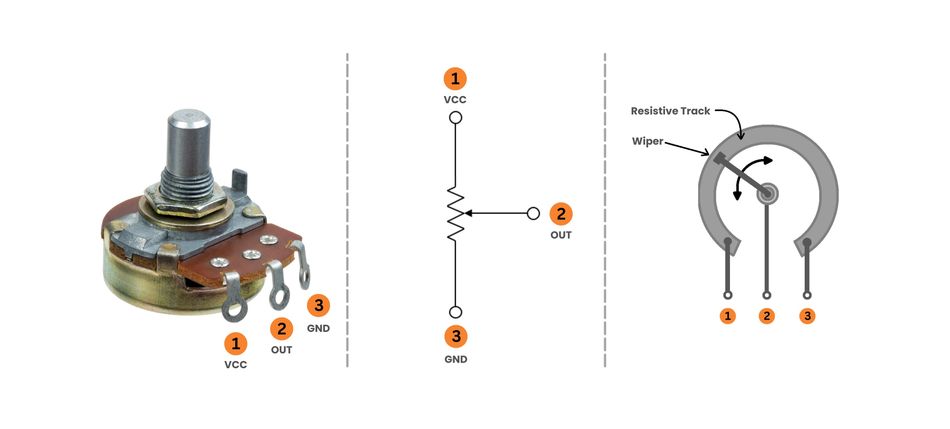
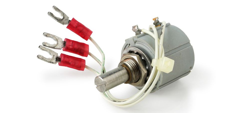
The potentiometer is a manually adjustable variable resistor consisting of three terminals. Two terminals are connected to the ends of a resistive element, while the third is a movable wiper that slides along it. The position of the wiper determines two resistance values that form a ratio. Once a reference voltage is applied across the outer terminals, the output voltage at the wiper represents a fractional portion of the input, following the voltage divider equation:
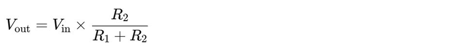
where R1 and R2 are the resistances between the wiper and each terminal of the resistive track.
In circuit design, a potentiometer schematic clearly illustrates this relationship, showing how voltage control is achieved through resistance variation. When only one end terminal and the wiper are used, the device operates as a rheostat, adjusting current instead of voltage. This mode is common in electronic circuits, such as motor speed control, light dimmers, and power supply regulation.
Schematic Symbol
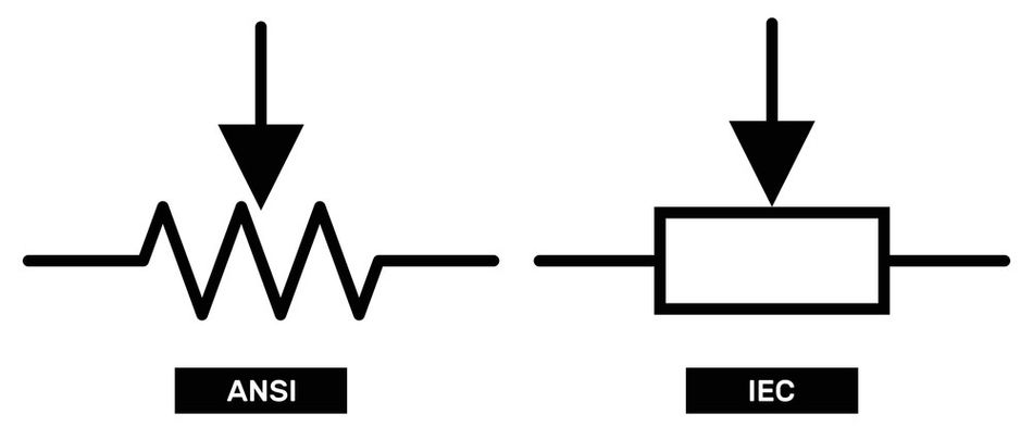
Potentiometer schematics vary slightly by standard. The International Electrotechnical Commission (IEC) symbol draws the resistive element as a rectangle with an arrow pointing to the midpoint, while the older American National Standards Institute (ANSI) symbol uses a zig‑zag resistor with a diagonal arrow. Both symbols show three terminals: two fixed end terminals and one wiper terminal. [1]
The potentiometer symbol may be annotated with terminal numbers—commonly “1” and “3” for the end terminals, and “2” for the middle pin (wiper). For rotary potentiometers, the circular orientation indicates rotational motion, while linear potentiometers display a straight wiring diagram. Neither orientation affects the electrical behavior but provides clarity in circuit diagrams and PCB layouts.
When used as a rheostat, engineers often connect the wiper to one end terminal to maintain continuity in case the wiper momentarily loses contact. This design practice prevents circuit interruption, ensuring smooth resistance variation even under vibration or wear.
Recommended Reading: What Are Schematics: The Blueprint Language of Engineering Decoded
Materials and Construction
The resistive element inside a potentiometer can be made from several materials:
| Material | Properties & Applications |
| Carbon Composition | Uses carbon ink molded on a phenolic substrate. It is low-cost, reliable, and provides acceptable noise and wear characteristics, making it the most common type. |
| Wirewound | Consists of a helical wire wound on an insulating core. It supports high power, offers long life, and is ideal for rheostats and precision potentiometers. However, discrete turns reduce resolution and produce a slightly coarse feel. |
| Conductive Plastic | A polymer-based resistive element with smooth motion and excellent resolution. It withstands millions of cycles and provides very low noise, commonly used in audio equipment, amplifiers, and precision control circuits. |
| Cermet | A ceramic–metal composite with exceptional stability and low temperature coefficient. It tolerates high temperatures and is widely used in trimpots, calibration systems, and automation equipment where reliability is crucial. |
The wiper, a spring-loaded electronic component, slides along the resistive track, converting mechanical movement into an electrical signal. In multi-turn designs, the wiper traverses the track several times to allow fine calibration. These are common in digital potentiometers or trimmer potentiometers integrated into microcontroller-based systems such as Arduino boards, where precise analog adjustments are needed.
Potentiometer Taper
Taper describes the relationship between the mechanical position and the resistance ratio of the wiper. In a linear taper, the resistances vary proportionally with wiper position: the middle position yields half of the full resistance. Linear pots are common for general signal adjustment and instrumentation.
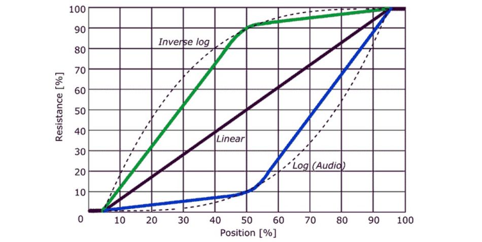
In contrast, logarithmic (audio) taper pots change resistance exponentially across the travel. They are used for volume control because the human ear perceives sound intensity logarithmically. Log‑taper pots provide a natural, smooth change in perceived volume. The inverse logarithmic taper (anti‑log) has the opposite curve and is used in circuits where counterclockwise rotation increases output, or in specialized tone‑control networks.
Manufacturers indicate taper using letter codes: B or LIN for linear, A or LOG for audio, and C or F for inverse log. [2]
Standard Values, Resolution and Codes
Potentiometers do not need a wide range of total resistances because the wiper can vary the output continuously. The common end‑to‑end values include 1 kΩ, 5 kΩ, 10 kΩ (the most common), 50 kΩ and 100 kΩ. Some specialized multi‑turn trimmers provide values up to several megohms. Resolution is limited by the mechanical construction – wire‑wound pots have discrete steps due to wire turns, whereas conductive‑plastic pots offer nearly continuous resolution.
Manufacturers mark taper and total resistance using standard codes. For example, “B10k” denotes a 10 kΩ linear pot; “A100k” denotes a 100 kΩ audio pot. A three‑digit code similar to surface‑mount resistor coding is sometimes used; the first two digits give the significant figures and the third digit is the multiplier (e.g., “103” means 10 kΩ).
Recommended Reading: How to Read Electrical Schematics: A Comprehensive Guide for Engineers
Types of Potentiometers and their Applications
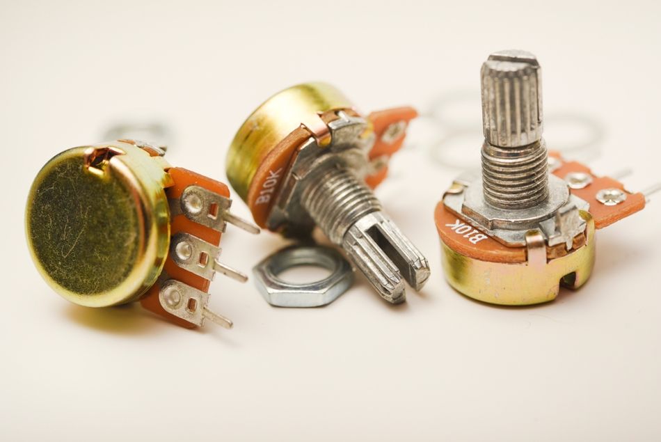
Rotary Potentiometers
Rotary pots are the most common type. A shaft rotates the wiper along a circular resistive element. The variants include:
Single‑Turn Pots – rotate roughly 270 ° and provide moderate resolution; used wherever a full rotation suffices.
Multi‑Turn Pots – use a worm‑gear or helical resistive track to allow 5–20 turns for high precision; common in calibration and trimpots.
Dual‑Gang or Multi‑Gang Pots – combine two or more pots on the same shaft to adjust multiple channels simultaneously; widely used in stereo volume or balanced control. Concentric shafts allow independent adjustment of multiple potentiometers on the same axis.
Servo or Motorized Pots – integrate a motor to drive the shaft, enabling remote or automated adjustment (e.g., audio mixers and remote volume control).
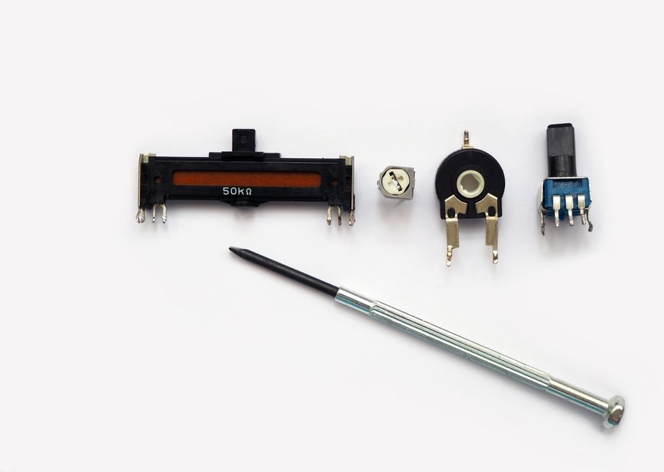
Linear and Slide Potentiometers
In linear or slider pots, the resistive element is laid out in a straight line and the wiper moves linearly. The types include:
Slide Pots – single slider controlling one channel, commonly used in audio mixing consoles and graphic equalisers.
Dual Slide Pots – one slider controlling two parallel pots (stereo faders).
Multi‑Turn Slide – linear trimmers actuated via a spindle for high precision.
Motorized Faders – linear pots with servo motors for automated mixing or remote control.
Trimmer and Preset Potentiometers
Trimmer potentiometers (trimpots or presets) are small devices mounted directly on printed circuit boards for one‑time calibration or occasional adjustment. They are often multi‑turn cermet or conductive‑plastic pots to provide fine resolution. An external tool (screwdriver) adjusts the wiper. Once set, they remain at a fixed position during normal operation.
Specialized Analog Pots
The additional sub‑types include:
Servo Pots – integrated into servo motors to provide position feedback by producing a voltage proportional to the shaft angle. A control system compares this feedback to a desired position and drives the motor until the difference is null.
Concentric Pots – two pots on the same axis with separate shafts; used for simultaneous tone and volume control.
Thumbwheel Pots – small rotary pots with tactile wheels for finger adjustment (e.g., brightness or instrument calibration).
Slide and Dual Slide – as described above; often used as position sensors for measuring displacement due to their linear relation between slider position and resistance.
Motorized Slide – remote control of faders in automation and instrumentation.
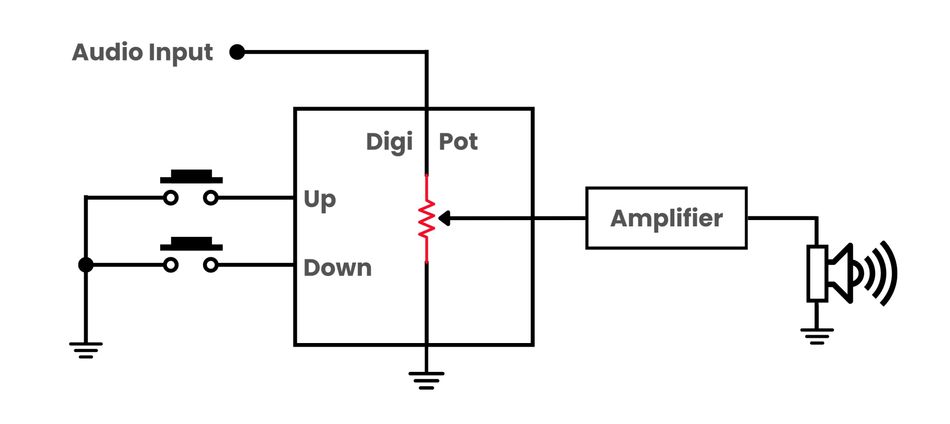
Digital Potentiometers (Digipots)
Modern electronic systems often require programmable control rather than manual adjustment. Digital potentiometer integrated circuits replace the mechanical wiper with a matrix of resistors and electronic switches controlled by digital signals.
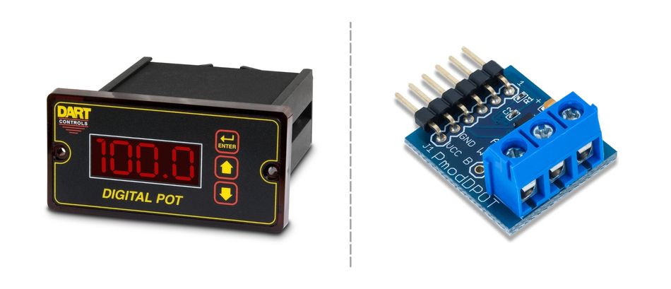
Digipots bridge the digital and analog domains, allowing software to set and vary the resistance or voltage‑divider ratio. [3] The key features include:
Electronics and Reliability – digipots are all‑electronic with no moving parts, so they are rugged and cannot be inadvertently adjusted.
Control Interfaces – most digipots use serial interfaces such as SPI or I²C; others implement up/down pushbutton control or rotary encoder interfaces. Multiple digipots can share a bus using chip‑select or address pins.
End‑to‑End Resistance Values – typical values range from 5 kΩ to 100 kΩ, with extended ranges from 1 kΩ to 1 MΩ. Designers choose a value based on the impedance needed in the circuit.
Resolution – the number of steps (taps) ranges from 32 to 1 024; even a 256‑step (8‑bit) digipot offers finer resolution than a mechanical pot.
Tolerance and Error – digipots have tolerances of ±10–20 % on the end‑to‑end resistance, though precision types with ±1 % tolerance exist. The on‑resistance and temperature coefficient of the wiper must be considered when precision matters.
Bandwidth and Distortion – the resistor network and switch capacitances create an RC low‑pass filter; low‑value digipots (≈1 kΩ) offer bandwidths up to ~5 MHz, while 1 MΩ devices may only allow ~5 kHz. Higher resistance reduces harmonic distortion because the switch resistance becomes a smaller fraction of the total.
Digipots support additional capabilities such as non‑volatile memory to store settings on power down, dual or quad channels for multi‑channel control. Features like shutdown mode to disconnect the resistor network and reduce current consumption (Microchip’s design guide lists options with 6–8 bit resolution, SPI/I²C or up/down interfaces, volatile and non‑volatile memory, and features such as WiperLock and shutdown). Some devices can operate at low supply voltages (1.8 V) or high voltages (±18 V) for analog signal ranges.
Applications Summary
Potentiometers appear in a wide range of systems:
| Application Area | Examples |
| User‑Controlled Inputs | Volume knobs, lighting dimmers, instrument control panels, game controllers. Automotive throttle pedals often use dual‑gang pots for redundancy. |
| Audio Control | Logarithmic potentiometers for volume and tone control, motorized faders in professional mixers. |
| Position/Angle Transducers | Measuring rotary or linear displacement in servo motors or joysticks, acting as position sensors or feedback elements. |
| Calibration and Tuning | Trimpots for adjusting reference voltages, sensor bridges, oscillator frequency or analog filter corner frequencies; they are set during manufacturing or service and left fixed. |
| Programmable Gain and Filters | Digital pots in programmable gain amplifiers (PGAs), variable filters, LED dimming, sensor calibration and remote tuning. |
| Microcontroller Inputs | Using a mechanical pot as an analog input to microcontrollers (ADC) for user input such as a knob to adjust brightness or menu selection. |
| Microcontroller Outputs | Controlling digipots via SPI or I²C to vary resistor values, enabling software‑adjustable gains, offsets or tuning. |
Recommended Reading: I2C vs SPI: A Comprehensive Comparison and Analysis
Wiring and Using Potentiometers in Circuits
Voltage Divider Configuration
The most common potentiometer wiring method is the voltage divider configuration. The two end terminals connect across a supply voltage (e.g., VCC and ground). The wiper output yields a fraction of this voltage proportional to the ratio of resistances. For example, a 1 kΩ pot with 5 V across it and the wiper at 30 % of travel outputs ≈1.5 V. This configuration is used for audio volume control, reference voltage adjustment or microcontroller inputs.
Because the output impedance equals the parallel combination of the two partial resistances, designers should ensure that the load connected to the wiper has an input impedance at least ten times larger than the potentiometer’s end‑to‑end resistance to minimize loading errors. For microcontroller ADC inputs, 10 kΩ pots and 1 MΩ ADC input impedance provide negligible loading.
Rheostat Configuration (Two‑Wire)
When only two pins are connected – typically the wiper and one end terminal – the potentiometer behaves like a variable resistor. This configuration controls current in series circuits, such as dimming an LED or controlling motor speed (with additional driver circuits). It is prudent to connect the unused terminal to the wiper to avoid an open circuit if the wiper loses contact.
Designers should be mindful of power dissipation: potentiometers are seldom rated for more than a watt, so they should not be used to directly control high‑power loads.
Step‑by‑Step Wiring
A reliable wiring procedure for mechanical pots is as follows:
Identify Pins: Use a multimeter to label the two fixed end terminals and the wiper (middle pin).
Power Off: Always disconnect power before wiring to prevent damage.
Mount the Pot: Secure the pot on a breadboard, PCB or panel; orient pins correctly.
Connect Ground: Connect one outer terminal to ground (0 V).
Connect Supply/Input: Connect the other outer terminal to the supply or signal to be controlled.
Connect Wiper: Connect the wiper to the circuit node that receives the variable voltage or current.
Optional Rheostat Safeguard: For two‑wire use, connect the unused outer terminal to the wiper.
Verify Operation: Reconnect power and turn the pot; verify that the output varies smoothly across the expected range.
In rheostat applications, an additional fixed resistor may be placed in series with the pot to limit the minimum resistance and protect components (e.g., limiting LED current). It is necessary to consider the derating curves in datasheets for power handling vs. ambient temperature.
Example: LED Dimmer
A simple LED dimmer uses a potentiometer as a rheostat. Connect a series resistor to limit current through the LED, then connect a 10 kΩ pot between the LED and ground. As the wiper moves, the total resistance in series with the LED increases or decreases, changing its brightness. Build‑Electronic‑Circuits demonstrates a similar circuit and notes that turning the shaft in one direction increases resistance and dims the LED, while the opposite direction brightens it.
Example: Volume Control
For audio amplifiers, a potentiometer wired as a voltage divider attenuates the input signal. The two end terminals connect to the signal source and ground; the wiper feeds the amplifier’s input. As the wiper moves toward ground, more signal is attenuated and volume decreases. The audio applications use logarithmic taper pots so that perceived volume changes uniformly with rotation.
Example: Wheatstone Bridge Calibration
Potentiometers can balance sensor bridges (e.g., strain gauge or thermistor Wheatstone bridges). A trimmer pot connected across one leg of the bridge allows fine adjustment to zero the bridge output. In rheostat mode, the pot can adjust a single resistor in the bridge.
Position Sensing and Servo Feedback
Pots serve as simple position sensors. In servo motors, a potentiometer mechanically linked to the output shaft produces a voltage proportional to the shaft angle. A control circuit compares this feedback voltage to a command voltage and drives the motor until the error is zero. The ability to convert angular or linear motion into a ratiometric voltage makes pots useful for joysticks, throttle pedals and linear actuators.
Recommended Reading: How to Wire a Potentiometer: A Comprehensive Guide for Engineers
4. Digital Potentiometers in Design
Internal Architecture
A digipot replaces the continuous resistive element with a string of resistors connected by electronic switches. The register‑controlled wiper selects one of the nodes along the resistor ladder. The device receives digital commands (via SPI, I²C or up/down pins) that load a value into an internal register, setting the wiper position. The entire network is fabricated using CMOS technology, so the devices are tiny (often 3 mm × 3 mm packages) and mount like ordinary integrated circuits.
In many digipots, the resistor ladder comprises 2N segments, where N is the resolution in bits (e.g., 8 bits → 256 segments). [4] The digital code sets the ratio R (above) : R (below). Because the wiper is an electronic switch, there is always a finite wiper resistance – often tens to hundreds of ohms – that adds series resistance to the selected node. Care must be taken not to exceed the specified maximum wiper current (commonly 1 mA).
Interface Options
Digipots come with several interface types:
SPI – Four‑wire serial interface (MOSI, MISO, SCLK, CS). Fast and simple to implement, used in devices such as Texas Instruments’ TPL0501 (256 taps).
I²C – Two‑wire interface (SDA, SCL) with addressable devices, allowing multiple digipots on the same bus.
Up/Down (U/D) – Minimal interface requiring only increment and decrement pulses plus chip‑select; suitable for pushbutton or rotary encoder control and used in Microchip’s MCP4011 digipot.
Pushbutton – Human‑operated buttons to increase or decrease the resistance without a microcontroller.
The non‑volatile digipots store the wiper setting in EEPROM or flash memory so that the last value is restored on power‑up; volatile types reset to mid‑scale or zero on power‑up. Some devices include shutdown pins or registers to disconnect the resistor ladder, reducing current consumption.
Selecting a Digital Potentiometer
When choosing a digipot, consider the following parameters:
End‑to‑End Resistance – Choose based on the impedance of the circuit. Typical values range from 1 kΩ to 1 MΩ.
Resolution – Higher bits give finer control but may require more code and cost. Common options are 64, 128 and 256 steps.
Tolerance and Temperature Coefficient – Evaluate whether the ±10–20 % tolerance is acceptable, or opt for precision digipots with ±1 % tolerance.
Bandwidth and Distortion – For audio or RF applications, ensure the digipot’s bandwidth meets the signal frequency and that THD is acceptable.
Power Supply and Signal Voltage – Ensure the digipot’s supply rails accommodate the signal range; low‑voltage devices may only handle 0–5 V, while high‑voltage digipots support ±15 V or more.
Memory Type – Non‑volatile devices remember settings, useful for calibration that must persist across power cycles.
Digital Potentiometer Applications and Circuits
Programmable Gain Amplifiers (PGAs): Op‑amp gain is set by the ratio of feedback and input resistors. Replacing one of these resistors with a digipot enables software‑controlled gain. The caution must be taken because the digipot’s tolerance and wiper resistance affect the overall gain error and bandwidth. Designers should keep the wiper current within ratings and avoid using the extreme ends of the digipot to minimize non‑linearity.
Programmable Filters: Varying resistor values in RC or active filters changes the cutoff frequency. Digipots allow microcontrollers to tune filters dynamically, compensating for component drift or altering response for different modes.
LED Dimming and Bias Control: Digipots can adjust LED brightness or bias currents in sensor circuits via microcontroller commands. LED thermal stabilization and closed‑loop gain control as typical applications.
Calibration and Sensor Trimming: A digipot can balance Wheatstone bridges or set reference voltages without manual adjustments. For example, a sensor bridge can be calibrated in manufacturing by writing a code to the digipot; the value is stored in its EEPROM and restored at startup.
Remote Volume or Tone Control: In audio systems, a digipot paired with an amplifier forms a digitally controlled volume control. Pushbutton or rotary encoder interfaces provide tactile feedback without exposing the user to analog signal paths.
Selection Guidelines and Design Considerations
Choosing Between Mechanical and Digital Pots
The decision depends on the application:
Mechanical Pots are ideal for user‑facing knobs requiring human interaction. They offer continuous adjustment, tactile feedback and simplicity. Use them for instruments, analog synthesizers, bench power supplies and tuning circuits. Mechanical pots have limited cycle life (tens to hundreds of thousands of cycles) and may exhibit contact wear or noise as they age.
Digital Pots suit systems requiring remote or programmable control, repeatable settings or calibration via software. They offer compact size, immunity to vibration and wear, and multi‑channel integration. Choose digipots when the circuit is inside an enclosed system or requires automatic adjustment. Be aware of their tolerance, limited voltage range and discrete steps. For audio or instrumentation requiring high resolution, choose digipots with more taps and low wiper resistance.
Taper Selection
Choose linear taper for general signal control, instrumentation and sensors where the relationship between knob position and output should be proportional. Use logarithmic taper for audio volume controls to compensate for the ear’s logarithmic response. Inverse log tapers are used where rotation direction and response need to be reversed.
End‑to‑End Resistance
Select a resistance high enough that the potentiometer’s loading of the preceding stage is minimal yet low enough that the subsequent stage does not significantly load the wiper. A common rule is to make the load impedance at least 10 times the potentiometer value. For microcontroller inputs, values between 5 kΩ and 100 kΩ are typical.
Power Rating and Derating
Mechanical pots are rated for maximum power dissipation (often <1 W). Because the wiper divides power between two resistances, a pot’s segments can overheat if too much current flows. Derate the power rating with ambient temperature and avoid using pots for high‑power loads; instead, use them to control active devices (e.g., FETs, op‑amps, TRIACs) that handle the power.
Environmental Considerations
For harsh environments, choose sealed or ceramic pots that resist dust, humidity and vibration. Multi‑turn wire‑wound pots are robust and handle higher temperatures. Conductive‑plastic pots provide long cycle life for frequent adjustments but may be sensitive to heat.
Recommended Reading: PCB Components: A Comprehensive Technical Guide to Passive, Active, and Electromechanical Parts
Conclusion
Potentiometers remain indispensable even in the age of digital electronics. Understanding their schematics, materials, types, and operation enables engineers to use them effectively as adjustable voltage dividers, rheostats, position sensors, or programmable resistors. Mechanical pots provide intuitive control and are ideal for user interfaces, while digital pots offer remote programmability and integration with microcontrollers. Selecting the right pot involves balancing resistance value, taper, resolution, power handling, and environmental requirements. With careful wiring and consideration of loading and tolerance, potentiometers deliver reliable and precise control in audio systems, instrumentation, calibration circuits, and embedded designs. As digital systems continue to advance, hybrid solutions combining mechanical feedback with digital programmability will provide the flexibility needed for next‑generation electronics.
Frequently Asked Questions (FAQs)
Q. What is the difference between a potentiometer and a rheostat?
A. A potentiometer has three terminals and acts as a variable voltage divider. When all three terminals are used, the output is taken from the wiper and provides a fraction of the input voltage. On the other hand, a rheostat uses only two terminals (wiper and one end) and functions as a variable resistor controlling current. By leaving one terminal of a pot unconnected or tying it to the wiper, a pot can be used as a rheostat.
Q. Why are logarithmic pots used for audio volume control?
A. Human hearing is non-linear, so logarithmic pots ensure smooth volume change. Linear pots produce uneven sound adjustment. For beginners, audio pots labeled “A” offer consistent, ear-friendly control across rotation.
Q. How do I choose the correct resistance value for a potentiometer?
A. Select a resistance that minimizes circuit loading but maintains desired maximum resistance. For most microcontroller or audio circuits, 5 kΩ–100 kΩ works well. Connect gnd, signal, and wiper pins properly according to the pinout.
Q. What are the limitations of digital potentiometers?
A. Digital pots handle limited voltage (0–5 V) and current, offering discrete steps instead of continuous adjustment. Temperature and tolerance affect potentiometer work accuracy. Avoid exceeding maximum resistance or current ratings to prevent failure.
Q. What is “hop‑on/hop‑off” resistance?
A. It’s the sudden resistance change at rotation limits when the wiper moves from metal contact to the resistive element. Designers avoid these regions using capacitors for signal smoothing and stable potentiometer work.
Q. Can potentiometers be used as position sensors?
A. Yes. When used as a voltage divider, the wiper voltage is proportional to the mechanical position. In servo systems, a pot attached to the output shaft provides feedback so the control circuit can compare desired and actual positions. Linear slide pots provide ratiometric measurement of displacement and can serve as inexpensive position transducers for robotics, joysticks, and industrial machines.
References
[1] Spectra Symbol. Potentiometer Symbol & Applications [Cited 2025 November 10] Available at: Link
[2] Wevolver. How to Wire a Potentiometer: A Comprehensive Guide for Engineers [Cited 2025 November 10] Available at: Link
[3] DigiKey. Digital Potentiometer Fundamentals [Cited 2025 November 10] Available at: Link
[4] Texas Instruments. TPL0501 256-Taps, Single-Channel, Digital Potentiometer With SPI Interface [Cited 2025 November 10] Available at: Link
in this article
1. Key Takeaways2. Introduction3. Fundamentals of Potentiometer Schematics4. Types of Potentiometers and their Applications5. Wiring and Using Potentiometers in Circuits4. Digital Potentiometers in Design7. Selection Guidelines and Design Considerations8. Conclusion9. Frequently Asked Questions (FAQs)10. References