Comprehensive Technical Guide to Hall Effect Sensors
This article presents a comprehensive engineering guide to Hall Effect Sensors, covering theoretical foundations, device structures, sensor types, specifications, applications, and practical integration strategies for modern electronic system design.

17 Apr, 2026. 15 minutes read
Key Takeaways
Hall Effect Sensors leverage the Lorentz force to detect magnetic field intensity and polarity in a non-contact manner, enabling durable sensing solutions.
Devices use a Hall element, bias current, and signal conditioning to generate an output voltage proportional to field strength or to switch between logic states.
Linear Hall Effect Sensors provide analog outputs (mV per gauss or tesla), while digital output variants (unipolar, bipolar, omnipolar, and latching) implement on/off thresholds with hysteresis.
Critical Specifications include sensitivity, supply voltage, hysteresis, temperature range, and magnetic operating points. Datasheets for parts such as Allegro A1302, Honeywell SS495, Melexis US1881, and Infineon MLX90393 exemplify these parameters.
Practical Integration requires pull-up resistors for open-collector outputs, bypass capacitors, proper power supply decoupling, and microcontroller interfacing.
Hall Effect Sensors compete with reed switches and magnetoresistive (AMR, GMR, TMR) technologies. Selection depends on sensitivity, power consumption, field orientation, and environmental robustness.
Introduction
In precision electronics and mechatronics, designers often need to detect motion, position, or current without physical contact. Hall Effect Sensors answer this need by exploiting the interaction between moving charge carriers and magnetic fields to produce an electrical signal. This phenomenon, discovered by Edwin Hall in 1879 while studying the behavior of electrons in a current-carrying conductor, supports a class of magnetic sensor technologies found in modern automobiles, industrial automation, and consumer devices. [1]
Hall Effect Sensors provide reliable non-contact sensing, ensuring long operational life and minimal wear. These sensors operate based on the Hall effect principle, where a voltage is generated across a conductor when exposed to a perpendicular magnetic field. This article presents a comprehensive engineering guide to Hall Effect Sensors, covering theoretical foundations, device structures, sensor types, specifications, applications, and practical integration strategies for modern electronic system design.
The Hall Effect: Physics and Lorentz Force
Hall Effect Basics
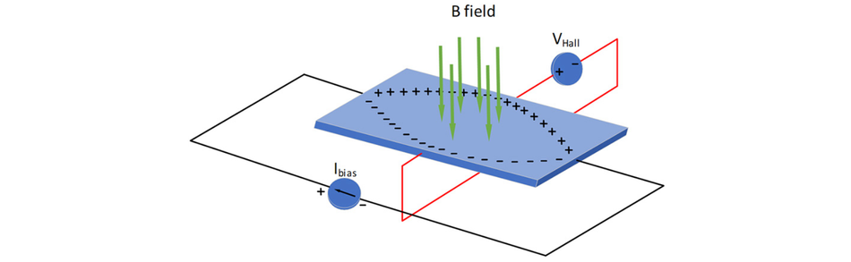
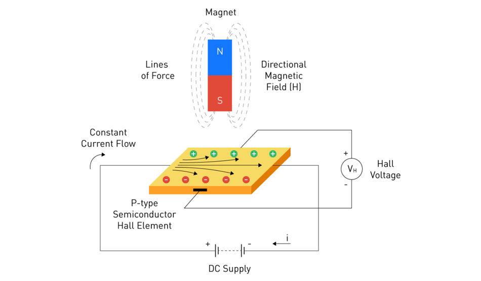
The Hall effect describes the generation of a transverse voltage output in a current-carrying conductor or semiconductor when exposed to a perpendicular magnetic field. In this condition, mobile charge carriers, typically electrons in n-type materials or holes in p-type materials, are subjected to the Lorentz force, expressed as F = q(v × B). This force drives carriers laterally, causing charge accumulation along one edge of the Hall element while leaving the opposite side depleted.
This separation creates a measurable potential difference, known as the Hall voltage, which is orthogonal to both the direction of electric current and the applied magnetic flux. The polarity of this voltage directly reflects the dominant carrier type, a discovery first demonstrated by Edwin Hall, enabling material characterization in semiconductor physics.
The magnitude of the Hall voltage V(H) for a conductor of thickness (t), carrying current (I) in a uniform magnetic flux density (B) is given by:
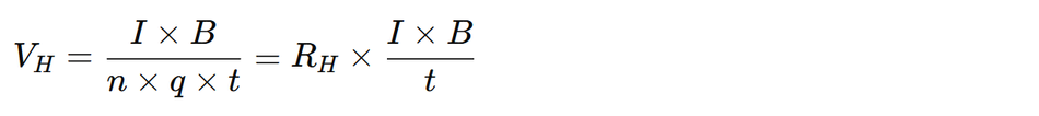
where n is carrier concentration, q is the elementary charge, and R(H) is the Hall coefficient. Due to their lower carrier density, semiconductor-based magnetic field sensors produce significantly higher output voltage, making them ideal for high-performance sensing applications.
Lorentz Force and Charge Carriers
The Lorentz force arises from the interaction between moving charges and a magnetic field. Once a current-carrying conductor is placed in a magnetic field, charges with velocity v experience a perpendicular force: F = qv × B [2]
For electrons moving through a conductor, this force deflects them to one side; for holes, it acts in the opposite direction. The separation produces the Hall potential that is sensed by electrodes along the sides of the Hall element. The magnitude of this force is proportional to charge velocity and magnetic flux density, underscoring why Hall sensors respond to field strength. This principle enables precise position sensing, speed sensor applications, and current sensing in modern automotive and industrial systems, where non-invasive measurement is critical.
Hall Elements and Semiconductors
Hall elements are typically fabricated from p-type or n-type semiconductor materials such as GaAs, InSb, or InAs. These materials provide high Hall coefficients, enabling detection of magnetic fields with small sensing areas and low bias currents. Thin wafer structures minimize thickness (t), increasing Hall voltage. The element is often configured in a cross-shaped layout to allow differential measurement of the Hall voltage while minimizing offset due to mechanical stress.
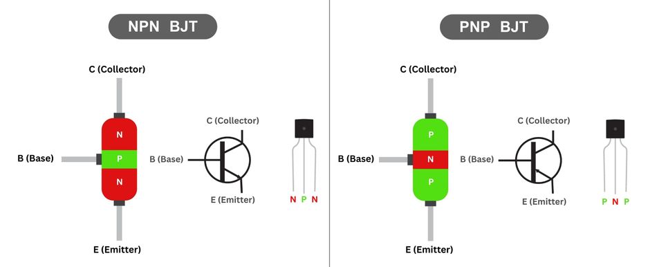
Modern implementations integrate the Hall element with integrated circuits, including amplifier stages, transistor-based switching elements (such as NPN configurations), and signal conditioning blocks. These ICs provide either analogue voltage output for linear Hall effect sensors or a digital output for Hall effect switches and latches, enabling seamless interfacing with a microcontroller.
This integration transforms raw transducer behavior into robust magnetic sensor systems suitable for non-contact measurement, widely used in actuators, position sensors, and advanced control systems.
Recommended Reading: What is a Semiconductor? A Comprehensive Guide to Engineering Principles and Applications
How a Hall Effect Sensor Works?
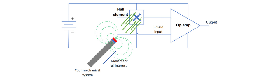
The complete Hall effect sensor integrates the Hall element with bias circuitry, amplification, and output stages on a single chip.
- Bias Current and Hall Element: The regulated current (often tens of milliamps) flows through the Hall element, establishing the baseline for the Lorentz force. When a magnetic field is applied perpendicular to the element, the Lorentz force deflects carriers, generating a Hall voltage across orthogonal electrodes.
- Amplifier and Signal Conditioning: The intrinsic Hall voltage is usually in the microvolt range, so integrated instrumentation amplifiers boost the signal to a useful level. For linear sensors, the output stage may include a transistor configured as an open-drain or push-pull driver to provide a voltage output proportional to the magnetic field. For digital sensors, a Schmitt trigger compares the amplified Hall voltage to thresholds, producing a digital logic level that toggles at specific magnetic flux densities.
- Offset Cancellation: Semiconductor imperfections and mechanical stress cause offset voltages even in the absence of a magnetic field. Modern Hall ICs employ chopper-stabilization or spinning current techniques to periodically reverse bias currents and subtract offsets. This yields better accuracy and temperature stability.
Types of Hall Effect Sensors
Hall sensors can be classified based on output type and magnetic switching behaviour:
Linear (Analog) Hall Sensors
Linear or analog Hall sensors provide a voltage output proportional to the applied magnetic field. They are commonly used for position sensing, current measurement, and closed-loop feedback.
Allegro A1302: This device provides a quiescent output voltage equal to half the supply voltage and a typical sensitivity of 1.3 mV/G (0.013 mV/mT). It operates from 4.5 V to 6 V supply and is rated for minus 40 C to 125 C. The A1301 variant offers 2.5 mV/G sensitivity. [3]
Honeywell SS495A: The general-purpose linear Hall sensor with supply voltage range 4.5 to 10.5 V, quiescent output at 2.5 V, and typical sensitivity around 3.3 mV/G. It can operate from minus 40 C to 150 C and has a response time of around 3 microseconds.
Melexis MLX90393: 3-axis Hall magnetometer that provides digital outputs via I2C or SPI. It offers selectable sensitivity settings, with the highest resolution around 0.161 microtesla per LSB (approximately 2.349 LSB/mT) and operates from a 2.2 to 3.6 V analog supply. Standby currents are tens of microamps.
These sensors integrate amplifier stages and integrated circuits to convert the small Hall voltage into a usable analog output signal.
Digital Hall Sensors and Switches
Digital Hall sensors produce a binary signal that switches when the magnetic field crosses predetermined thresholds. They are widely used for limit detection, gear tooth sensing, and brushless motor commutation.
Unipolar Hall Effect Switches trigger when a single magnetic polarity (usually the south pole) exceeds an operating point B(OP) and reset when the field falls below a release point B(RP). The A3144 is a popular unipolar switch that operates from 4.5 to 24 V and includes an open-collector output. For proper logic levels, a 10 kilo-ohm pull-up resistor is placed between VCC and the output, and a 0.1 microfarad bypass capacitor helps filter noise. The device consumes roughly 3.5 mA at 5 V.
Bipolar and Latch Hall Sensors require both polarities for toggling. The bipolar switch turns on when exposed to the south pole and off with the north pole. Latch devices maintain their output state until the opposite polarity field crosses the release point. The Melexis US1881 Hall latch operates over 3.5 to 24 V, draws about 5 mA, and has operate and release points in the 0.5 to 9.5 mT range with hysteresis around 7 to 12 mT. Its open-drain output requires a pull-up resistor, and the datasheet recommends a 100 nF bypass capacitor and reverse voltage protection.
Omnipolar Hall Effect Switches respond to either magnetic polarity. Devices like the Honeywell SS360NT operate from 3 to 24 V (limited to 12 V on some models), with supply currents around 3.5 to 6 mA and a maximum output current of 20 mA. They have operating and release points around 30 G (3 mT) and hysteresis of 40 to 80 G.
Hall Effect Latches vs. Switches
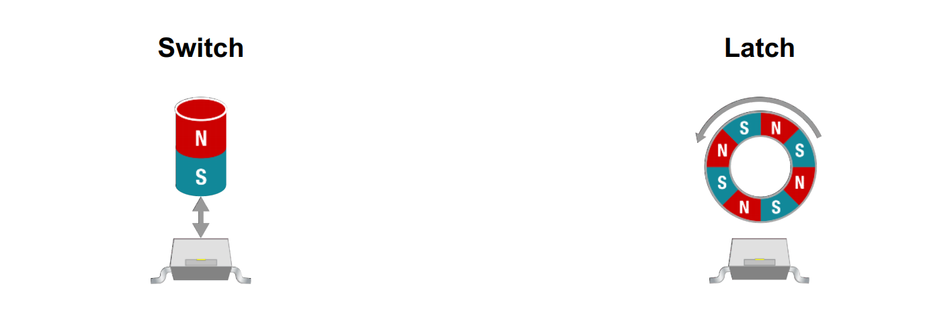
Switches provide on/off outputs with no memory; they turn on at B(OP) and off at B(RP) (unipolar or omnipolar). They are ideal for detecting proximity or speed when the magnet always moves in the same direction.
Latches remember their state; once they switch on, they remain latched until a magnetic field of opposite polarity resets them. They are essential in brushless DC motors where the sensor ensures proper commutation sequence.
3-Axis and 3-D Hall Sensors
Advanced Hall effect sensors incorporate multiple Hall element structures to measure orthogonal components of the magnetic field. These devices enable full 3D position sensing and vector-based field measurement. Devices like the MLX90393 offer 3-axis measurements with programmable sensitivity and digital interfaces. These sensors enable 3-D position sensing and magnetometer applications, such as joystick controllers, compass modules, and non-contact potentiometers.
Recommended Reading: Types of Switches: Complete Engineering Guide
Key Specifications of Hall Sensors
Once selecting a Hall sensor, engineers must evaluate several key specifications from the datasheet:
Sensitivity
Sensitivity specifies how much output voltage change corresponds to a unit magnetic field. For linear devices it is given in mV per gauss (mV/G) or mV per millitesla. The A1302 has 1.3 mV/G sensitivity, while the SS495A offers approximately 3.3 mV/G. Higher sensitivity allows detection of weaker fields but may increase noise susceptibility.
Quiescent Output and Ratiometric Behaviour
Analog sensors often provide a quiescent output voltage (QOV) at zero magnetic field. Ratiometric devices produce outputs proportional to the supply voltage; for example, the QOV of A1302 is 50% of the supply. Designers should account for QOV when interfacing to analog-to-digital converters (ADCs).
Operate and Release Points, Hysteresis
Digital sensors define operate B(OP) and release B(RP) thresholds. Hysteresis B(HYST) = B(OP) minus B(RP) prevents output chatter due to noise or vibration. The US1881 latch exhibits a hysteresis range of 7 to 12 mT, while the SS360NT omnipolar switch has a hysteresis range of 40 to 80 G.
Supply Voltage and Current
Hall ICs require a supply typically between 2 V and 24 V. Low-voltage devices like the MLX90393 operate at 2.2 to 3.6 V, whereas general-purpose digital switches handle up to 24 V (A3144, US1881). Supply current ranges from microamps in 3-axis magnetometers to several milliamps for continuous-time linear sensors; the A1302 draws a few milliamps, while the US1881 uses approximately 5 mA.
Temperature Range and Stability
Automotive and industrial applications demand operation across wide temperature ranges. The A1302 is specified from minus 40 C to 125 C, the SS495A covers minus 40 C to 150 C, and the US1881 latch has grades up to 150 C. Temperature coefficients of sensitivity and offsets should be considered when high accuracy is required.
Response Time and Bandwidth
Response time indicates how quickly the sensor output reacts to changes in the magnetic field. Linear sensors like the SS495A have response times around 3 microseconds, enabling bandwidths of hundreds of kilohertz. Digital switches are usually faster due to their binary nature, but may include internal filters for noise suppression.
Output Stage and Current Capability
Many Hall effect switches use open-collector NPN or open-drain outputs that can sink only limited current (for example, 20 mA for SS360NT). [4] A pull-up resistor to the supply or microcontroller voltage is required. Some linear sensors provide push-pull outputs capable of sourcing and sinking current, simplifying interfacing. Always check the output type and ensure proper pull-up values and drive currents.
Recommended Reading: Current-Limiting Resistor: Theory, Design and Practical Applications for Engineers
Applications of Hall Effect Sensors
Automotive Applications
Automotive systems rely heavily on Hall effect sensors because they offer durable non-contact detection immune to oil, dust, and vibration. The examples include:
Crankshaft and Camshaft Position Sensing: Digital Hall latches detect the angular position of rotating shafts in engine control units for ignition and fuel injection timing. Hysteresis ensures stable switching even with mechanical vibration.
Wheel Speed for Anti-Lock Braking Systems (ABS): Hall gear-tooth sensors count teeth on rotating wheels to compute speed and detect wheel slip.
Throttle and Pedal Position Sensors: Linear Hall sensors measure pedal displacement for drive-by-wire throttle control. They replace potentiometers due to better durability and redundancy.
Seatbelt and Seat Position Sensors: Hall effect switches detect seat occupancy and seatbelt latch state for airbag deployment systems.
Electric Power Steering and BLDC Motor Control: Latching Hall sensors commutate brushless DC motors by detecting rotor magnet positions, enabling efficient control and torque assistance.
Industrial and Consumer Applications
Proximity and Position Sensing: Hall sensors serve as non-contact limit switches in assembly equipment, robotics, and CNC machines. Omnipolar sensors allow detection of magnets regardless of polarity.
Speed and Rotation Monitoring: Tachometers and encoders employ digital Hall sensors to count rotations in fans, pumps, and smart meters. The absence of mechanical contacts improves reliability.
Current Sensing: When combined with a magnetic core surrounding a conductor, linear Hall sensors measure current by detecting the magnetic field generated by the current. Commercial current transducers integrate Hall elements with cores and offer galvanic isolation.
Keyboards and Input Devices: Some mechanical keyboards use Hall switches for contactless key detection, delivering smooth actuation and long life. Each key has a small magnet that actuates a Hall sensor below it.
Consumer Devices: Smartphones and laptops use Hall sensors to detect cover closure (screen lid detection), while drones and e-bikes employ them for speed and position feedback.
Advantages of Hall Sensors
Non-contact sensing eliminates mechanical wear, friction, and arcing, ensuring long operational life.
Immunity to environmental factors such as dust, moisture, and vibration, making them suitable for automotive and industrial use.
Ability to detect both magnetic field strength and polarity, enabling versatile sensing applications.
Wide temperature and supply voltage ranges suitable for automotive and industrial environments.
Availability of both analog and digital output formats, simplifying integration with a microcontroller without complex external circuitry.
These advantages make Hall effect sensors a preferred choice for modern sensing solutions requiring durability, precision, and high-performance operation across diverse applications.
Circuit Integration and Design Considerations
Reading the Datasheet
Datasheets provide critical information for integrating a Hall effect sensor. Important sections include electrical characteristics (supply voltage, current, output type), magnetic specifications (operate and release points, hysteresis), temperature range, and pin configuration. Always verify the recommended operating conditions; exceeding absolute maximum ratings can damage the sensor.
Biasing and Pull-Up Resistors
Open-collector or open-drain outputs require an external pull-up resistor to define a valid logic high level. For the A3144, a 10 kilo-ohm resistor from VCC to the output is typical. Choose a resistor value that ensures sufficient current-sinking capability while meeting the logic threshold requirements. For latching sensors like the US1881, the pull-up resistor also influences output rise time and should match the microcontroller input characteristics.
Decoupling and Bypass Capacitors
Hall ICs operate at high internal bandwidths and are susceptible to supply noise. Include a bypass capacitor (for example, 0.1 microfarad or 100 nF) between the supply and ground pins placed close to the IC. The US1881 datasheet recommends a 100 nF capacitor, and many unipolar switches (A3144) similarly benefit from local decoupling.
Reverse Voltage and Transient Protection
Protect the sensor from accidental reverse-supply connections or voltage spikes. For the US1881, the datasheet suggests using a series resistor or diode for reverse-voltage protection. Automotive applications may require additional transient suppression (e.g., TVS diodes) due to inductive loads and load-dump events.
Magnetic Circuit Design
Selecting and placing the magnet are essential for reliable operation. Determine the magnet size and material to generate the desired magnetic field at the sensor location. Ensure that the magnet orientation provides the correct polarity and field strength. Consider temperature coefficients of magnets (for example, neodymium loses strength at high temperatures) and mechanical tolerances in the assembly. For analog sensors, ensure the field remains within the linear range; for digital sensors, verify that the operate and release points are crossed reliably during operation.
Microcontroller Interfacing
Hall sensors interface readily with microcontrollers. Digital sensors connect to GPIO pins configured for interrupt detection. Use edge detection to capture transitions for speed or position. Linear sensors feed analog voltages into ADC channels; calibrate the ADC to account for quiescent voltage and convert measured voltage to magnetic field. For 3-axis sensors like the MLX90393, communicate over I2C or SPI and configure resolution and sampling rate via registers.
Calibration and Temperature Compensation
Offsets and sensitivity drift over temperature may require calibration. Many sensors offer factory trimming to minimize offset; some provide on-chip temperature sensors to compensate measurements. In high-precision applications (current sensing), implement firmware algorithms to correct for drift using periodic zero-field calibration or look-up tables.
Recommended Reading: How to Wire a Potentiometer: A Comprehensive Guide for Engineers
Comparison with Alternative Sensors
Reed Switches
Reed switches consist of two ferromagnetic reeds sealed in a glass capsule. Bringing a magnet near magnetizes the reeds, causing them to close and complete an electrical circuit. Removing the magnet opens the circuit. Reed switches require no power and provide true zero leakage when open, making them attractive for simple proximity detection and low-power designs.

However, they are mechanical devices; contact bounce can cause multiple pulses, and the glass capsule is fragile. The switching speed is slower than that of semiconductor devices, and the contacts can wear out after repeated cycling. Typical applications include door/window sensors, float level sensors, and bicycle speedometers.
Magnetoresistive Sensors (AMR, GMR, TMR)
Magnetoresistive sensors change resistance in response to an applied magnetic field. AMR sensors respond to fields parallel to the sensor plane; they can detect both magnetic poles and are less sensitive to field direction. GMR and TMR sensors provide higher sensitivity and lower noise; TMR (tunnelling magnetoresistance) offers the highest sensitivity but is limited to narrower field ranges around ±100 mT. [5] MR sensors are resistive elements, so they consume less power and exhibit faster start-up times compared with Hall sensors. However, their output is typically differential, requires signal conditioning, and is more sensitive to magnetic hysteresis and temperature effects. MR sensors are often used for precise angle sensing (end-of-shaft encoders) and high-resolution current measurement.
Inductive Sensors
Inductive proximity sensors detect metallic targets by measuring changes in inductance when a conductive object enters the sensor's electromagnetic field. They are robust for detecting metal objects at short ranges but cannot detect non-conductive magnets or provide polarity information. Inductive sensors require high frequencies and may consume more power.
Recommended Reading: What is a Sensor? Comprehensive Guide to Engineering Principles and Applications
Selection Criteria and Design Considerations
Once choosing a sensor, evaluate the following factors:
Magnetic Field Strength and Range: Determine the expected field. For weak fields (<1 mT), choose high-sensitivity Hall sensors or MR sensors. For strong magnets, standard Hall effect switches suffice.
Output Type: Decide whether analog proportional output or digital switching is needed. Analog sensors enable closed-loop control and measurement; digital sensors simplify logic detection.
Polarity and Hysteresis Requirements: For unidirectional sensing, choose unipolar or omnipolar sensors. For applications requiring memory or direction detection, use latching (bipolar) sensors.
Supply Voltage and Power Consumption: Battery-powered systems may favor low-voltage sensors (MLX90393) or MR sensors with microamp currents. Industrial systems may supply 5 V or 12 V and allow higher currents.
Temperature Range and Environment: Automotive and industrial environments require sensors with wide temperature ranges and robust packaging. Ensure that the sensor and magnet materials meet thermal specifications.
Accuracy and Linearity: For precision measurement, choose linear Hall sensors with low offset and drift. Calibration and offset cancellation techniques help improve accuracy.
Size and Packaging: Consider SOT-23, TO-92, LGA, or custom packages. 3-axis magnetometers may come in tiny QFN packages suitable for compact devices.
Cost and Availability: Evaluate vendor support, supply chain stability, and pricing. Popular brands include Allegro, Honeywell, Melexis, Infineon, and Texas Instruments.
Recommended Reading: QFN Packages: A Guide to High-Performance Electronics Encapsulation
Conclusion
Hall effect sensors combine fundamental physics with integrated circuit technology to provide versatile, non-contact magnetic field sensing. The underlying Hall effect arises from charge carriers deflected by the Lorentz force in a conductor, producing a voltage proportional to the magnetic field. Modern Hall sensors integrate Hall elements, bias current sources, amplifiers, and comparators to deliver analog or digital outputs. Engineers can choose from a wide variety of sensor types: linear analog sensors for proportional measurement, digital switches and latches for on/off detection, omnipolar sensors for ease of use, and 3-axis magnetometers for spatial field measurement.
Understanding key specifications (sensitivity, hysteresis, supply voltage, temperature range, and response time) is essential when evaluating datasheets. Proper circuit integration with pull-up resistors, decoupling capacitors, and magnetic circuit design ensures reliable operation. While Hall sensors face competition from reed switches and magnetoresistive technologies, they remain the dominant solution for many automotive, industrial, and consumer applications due to their robustness, versatility, and cost-effectiveness. The new developments, like 3-D Hall ICs and tunable magnetoresistive sensors, promise even greater performance and functionality.
Frequently Asked Questions (FAQs)
1. What is a Hall effect sensor, and how does it work?
A. Hall effect sensor is a semiconductor device that detects a magnetic field using the Hall effect. When electric current flows through a Hall element, the Lorentz force deflects charge carriers, generating a measurable Hall voltage converted into analog or digital output signal.
2. What are the differences between analog and digital Hall sensors?
A. Linear Hall effect sensors provide a continuous voltage output proportional to magnetic field strength, ideal for position sensing and current sensing. Digital Hall effect switches generate binary output signals using thresholds and hysteresis, making them suitable for switching, speed detection, and control systems.
3. What is hysteresis in a Hall sensor, and why is it important?
A. Hysteresis is the difference between operate and release points in digital Hall effect sensors. It prevents rapid switching due to noise or vibration when the magnetic field fluctuates near thresholds, ensuring stable, reliable output signal performance in real-world applications.
4. How do you interface a Hall effect switch to a microcontroller?
A. The Hall effect switch typically uses an open-drain or open-collector transistor output. The pull-up resistor connects the output to the supply voltage, enabling proper logic levels. A microcontroller reads the digital signal, often using interrupts for accurate edge detection.
5. Can Hall effect sensors measure current directly?
A. Yes, Hall effect sensors enable current sensing by detecting the magnetic field generated by current flow in a conductor. With a magnetic core, they act as isolated transducers, measuring AC or DC current without direct electrical contact.
6. How do Hall sensors compare to magnetoresistive (MR) sensors?
A. Hall effect sensors measure perpendicular magnetic flux with robust performance and simple integrated circuits. MR sensors offer higher sensitivity and lower noise but require complex conditioning. Hall sensors remain widely used due to cost-effectiveness, durability, and ease of integration.
7. What future developments can we expect in Hall effect sensor technology?
A. Future Hall effect sensors will feature advanced integrated circuits, improved sensitivity, and lower power consumption. Innovations include smart sensors with embedded processing, enhanced 3D sensing, and hybrid technologies combining Hall and MR principles for high-performance applications in robotics and IoT.
References
[1] Wikipedia. Hall Effect Sensor [Cited 2026 April 12]; Available at: Link
[2] Lumen Learning. Magnetic Force on a Current-Carrying Conductor [Cited 2026 April 12]; Available at: Link
[3] DigiKey. Allegro - A1301 and A1302 [Cited 2026 April 12]; Available at: Link
[4] Honeywell. High Sensitivity Latching Digital Hall-effect Sensor ICs: SS360NT, SS360ST, SS360ST-10K, SS460S, SS460S-T2, SS460S-LP [Cited 2026 April 12]; Available at: Link
[5] Infineon. Magnetic Marvels: Hall, AMR, GMR & TMR Technologies [Cited 2026 April 12]; Available at: Link
in this article
1. Key Takeaways2. Introduction3. The Hall Effect: Physics and Lorentz Force4. How a Hall Effect Sensor Works?5. Types of Hall Effect Sensors6. Key Specifications of Hall Sensors7. Applications of Hall Effect Sensors8. Circuit Integration and Design Considerations9. Comparison with Alternative Sensors10. Selection Criteria and Design Considerations11. Conclusion12. Frequently Asked Questions (FAQs)13. References