What Is a Servo Drive? Architecture, Control Loops, Fieldbus, and Sizing
This guide covers what is inside a servo drive, how its nested servo loops behave, how EtherCAT and CANopen interfaces change the architecture, and how to size, tune, and safely commission one.

23 Aug, 2026. 17 minutes read
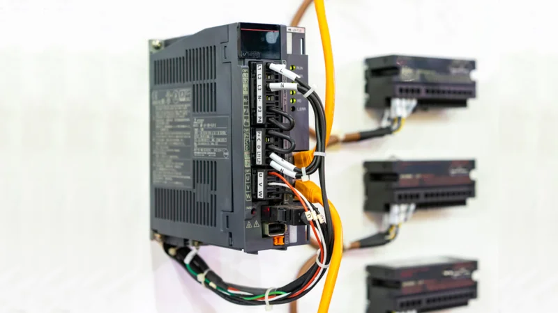
AC Servo Drive Unit for Machine Control and Manufacturing
Key Takeaways
What is a Servo Drive: A servo drive is an electronic device that amplifies a low-power command signal into controlled motor current, torque, velocity, and often position loops, using feedback signals from an encoder or resolver.
Current Loop Foundation: The current loop is the foundation. Its bandwidth sets the ceiling for everything above it, typically exceeding the speed and position loop bandwidths by roughly ten times.
Carrier Frequency Bandwidth Limits: Traditional PI current controllers cap bandwidth at about 10% of the PWM carrier frequency, so a 10 kHz carrier yields roughly 1 kHz of torque response.
Standardized Fieldbus Profiles: Modern drives expose a standardized fieldbus profile (CiA 402, standardized as IEC 61800-7-201), which is why a drive from one vendor can be commissioned much like another on EtherCAT, CANopen, or EtherNet/IP.
Multivariable Sizing Constraints: Sizing is a thermal and energy problem, not just a torque problem: continuous versus peak current, DC bus voltage, regenerated energy, and inertia ratio all constrain the choice.
Introduction
The servo drive is an electronic control unit that regulates the position, speed, and torque of a servo motor with high precision. It interprets command signals, processes feedback from encoders or resolvers, and continuously adjusts motor current to maintain the required motion profile, linking the motion controller to the motor.
Modern systems rely on tightly coordinated current, velocity, and position control loops, allowing fast response, low error, and stable operation under changing loads. The servo drive may also integrate safety functions, diagnostics, motion profiles, and industrial communication interfaces such as EtherCAT, PROFINET, CANopen, or EtherNet/IP. Selecting the right servo drive requires more than matching motor voltage and power; engineers must consider peak and continuous current, inertia ratio, regeneration, control bandwidth, fieldbus compatibility, and environmental conditions.
This article explains servo drive architecture, control loops, fieldbus communication, commissioning considerations, and practical sizing principles for advanced industrial motion systems.
What a Servo Drive Actually Does?
The servo drive is an electronic amplifier that powers electric servomechanisms. It accepts a command from a control system, amplifies it, and delivers current to the motor, while a feedback device reports what the motor actually did so the drive can correct the difference.
That correction is the main point. The word "servo" refers to the ability of a system to adjust its operating parameters continuously based on feedback rather than running open-loop, and this constant feedback loop keeps performance stable under variable load. [1]
The closed-loop system includes the drive, servo motor, and feedback device, and it is commanded by an analog or digital signal. The command signal usually originates in a PLC, CNC, or dedicated motion control controller.
Terminology varies by vendor and decade. The "servo drive," "servo amplifier," and "drive unit" all describe the same box. Older literature calls it the amplifier because it amplifies a control signal into higher-power motion. [2]
The drive is not restricted to rotary brushless motors. Commercial drives commonly support brushed and brushless servo motors, a linear motor, two-phase and three-phase stepper motors, AC induction motors, and voice coils.
Recommended Reading: Servo Motor: How It Works, Types, Specifications, and Sizing
Inside the Drive: The Power Stage
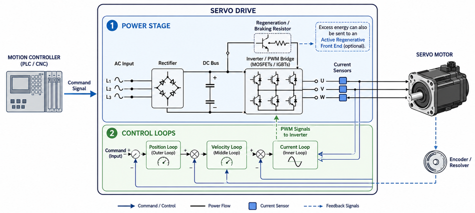
Fundamentally, a servo drive comprises two essential components: the power stage and the control loops.
Rectifier and DC Bus
In a single-axis AC-input drive, a diode bridge converts incoming AC to DC, and bus capacitors smooth it. That DC section is the bus, and its voltage is roughly 1.414 times the input voltage. [2]
In practice, that means 400 V AC three-phase produces a nominal bus of about 565 V DC, and 480 V AC produces about 680 V DC. [3] The bus capacitors absorb micro-fluctuations from rectifier switching and provide ride-through for brief supply interruptions.
The bus voltage matters because it sets the available motor speed. Back EMF rises with speed, and once it approaches the bus voltage, the drive can no longer force current into the winding, so torque collapses at the top of the speed range.
Inverter and PWM
The bus is then chopped by transistors, typically MOSFETs or IGBTs, arranged as an H-bridge for DC motors or a three-phase bridge for AC and brushless motors. Varying the on-time varies the average terminal voltage, which is how a pulse-width-modulated amplifier controls current. [2]
The transistors act as switches that let current flow through the winding in either direction, giving forward or reverse motion. Combined with the regeneration path, this gives four-quadrant operation: accelerating, decelerating, and braking in either direction of rotation.
Here, carrier frequency is a real design trade-off. Raising it from 10 kHz to 30 kHz increases the achievable current-loop bandwidth. But it also increases inverter switching losses, demands more gate-drive power, and adds heat that must be removed with larger heatsinks, fans, or coolant. [4] That thermal budget is what limits power density in a compact drive.
Regeneration and the Shunt Resistor
Once a load decelerates, the motor becomes a generator and pushes energy back onto the bus. Once the bus rises to a defined threshold, a regeneration transistor switches the excess into a shunt resistor. The alternative is an active front end that returns the energy to the line.
Drives typically trip on overvoltage when the bus exceeds nominal by 10% to 15% during regenerative braking, so the shunt has to act before that point.
Recommended Reading: Transistor as a Switch: Theory and Practical Implementation for Digital and Hardware Engineers
The Servo Loops
The servo loops provide proportional control of the motor from the command signal. A simple drive contains a single loop controlling torque. More advanced drives add a velocity loop and may also close the position loop. Almost all drives close the current loop, but not all close the outer two.
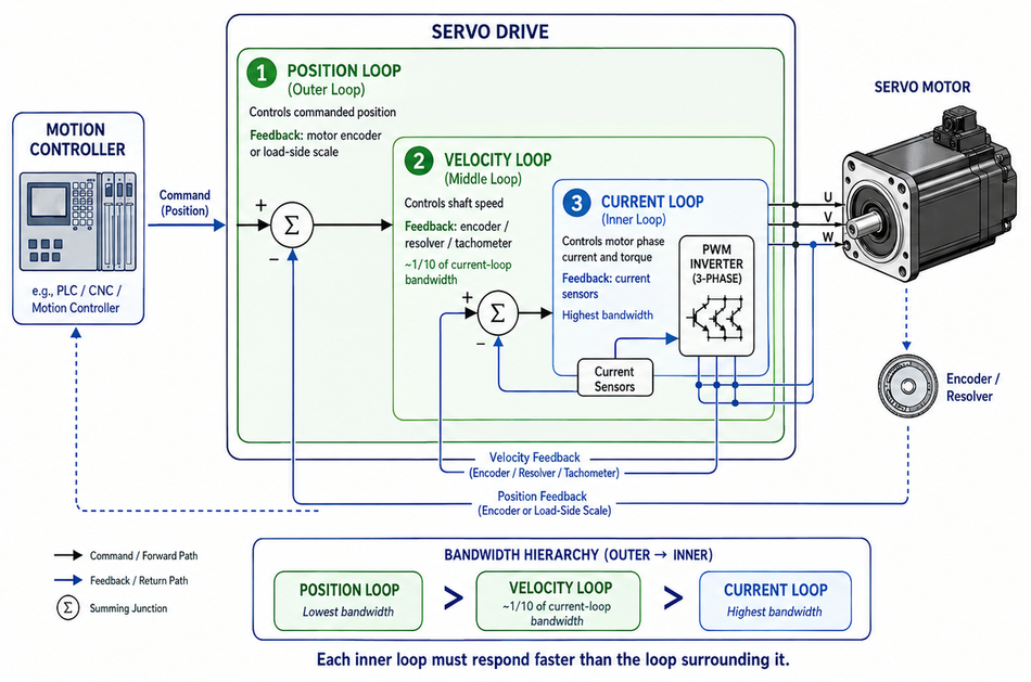
Each loop feeds the next and monitors its own feedback signals to make real-time corrections. Servo applications typically use three nested loops: current, velocity, and position. [4]
The current loop controls motor phase current and therefore motor torque using feedback from current sensors. It has the highest bandwidth and establishes the performance ceiling for the outer loops.
The velocity loop regulates shaft or carriage speed using feedback from an encoder, resolver, or tachometer and typically operates at roughly one-tenth of the current-loop bandwidth.
The position loop compares commanded position with feedback from a motor encoder or load-side scale, calculates the following error, and operates at the lowest bandwidth of the three.
Each inner loop must respond faster than the loop surrounding it. This separation prevents the outer controller from demanding changes faster than the inner controller can physically produce.
Why the Current Loop Dominates?
The current loop is the foundation of servo performance because torque is how the motor accelerates, decelerates, and rejects disturbances. Its bandwidth therefore limits how aggressively you can tune the velocity and position loops.
Conventional PI current controllers often restrict current-loop bandwidth to approximately 10% of the PWM carrier frequency. With a switching frequency near 10 kHz, this typically produces around 1 kHz of torque-response bandwidth.
Higher bandwidth can be achieved either by increasing the PWM frequency, which raises switching losses, or by reducing computational delay. Modern real-time MCUs can sample phase currents, perform field-oriented control calculations, and update the PWM within a single switching cycle. Processing and PWM updates can take less than 500 nanoseconds, enabling measured current-loop bandwidths of roughly 3.3 kHz while retaining a 10 kHz carrier.
The digital transport delay remains another important limitation. Once motor speed and control bandwidth increase, computation and sampling delays reduce phase margin. Controllers that fail to account for these delays can therefore become unstable or lose current-control accuracy at higher operating speeds.
Where the Loops Physically Live?
The location of each servo loop depends on the system architecture, not a fixed design rule. In many high-performance systems, the servo drive closes the current and velocity loops while a central motion controller closes the position loop. Other architectures leave the drive in torque mode and place both velocity and position control in the external controller.
The torque mode is particularly useful in force-controlled processes such as press fitting, screwdriving, and web tensioning, where applied torque or force matters more than reaching a predefined position.
Historically, most servo loops closed every 250 microseconds to 2 milliseconds, which is exactly the interval a fieldbus has to keep up with. Once those loops are distributed between a controller and drive, the industrial fieldbus must exchange commands and feedback within that control interval while maintaining sufficiently low and predictable latency. [2]
Recommended Reading: PID Controller & Loops: A Comprehensive Guide to Understanding and Implementation
Feedback Devices and Sensors
The feedback device can be a potentiometer, Hall effect sensor, a tachometer, a resolver, an encoder, a linear transducer, or any other appropriate sensor. Many machines use two feedback systems at once: one on the motor for commutation and velocity, one on the load for true position.
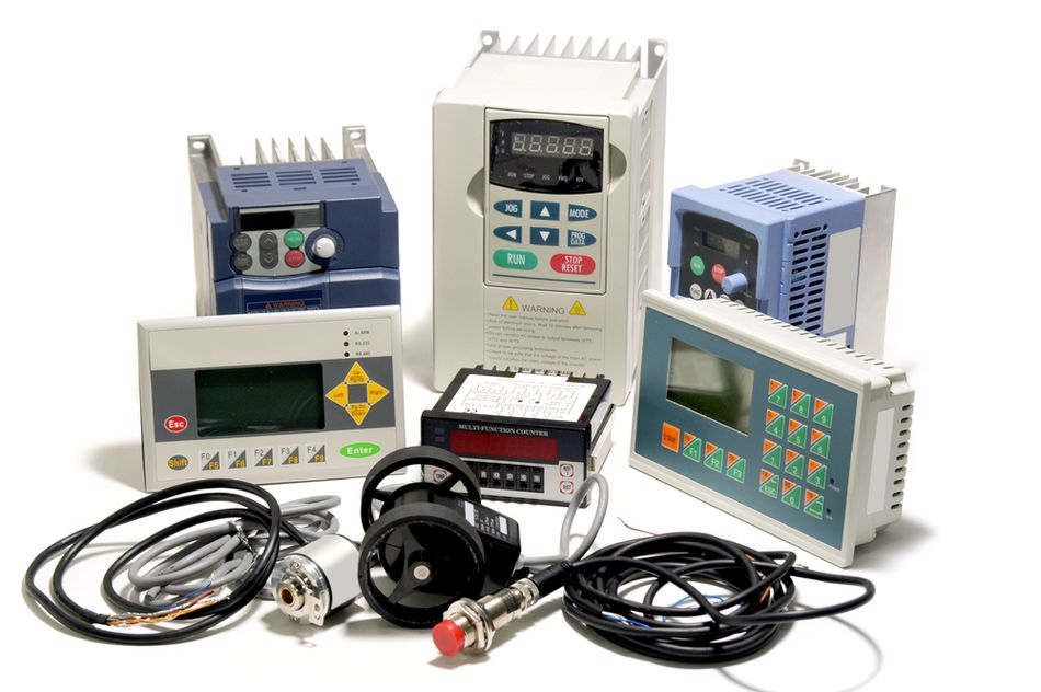
Encoders emit quadrature pulses from an optical or magnetic scale. Two channels offset by 90 degrees give velocity, direction, and position, and reading both edges of both channels yields four times the line count in quadrature counts.
Resolvers are rotating transformers that output two sine waves 90 degrees apart, which the drive decodes into an encoder-like signal. Pole counts in commercially available motors commonly range from 1 to 80.
The decoding step is where resolvers pay a penalty. Resolver-to-digital conversion imposes a bandwidth limit that tightens as you demand more bits: roughly under 100 Hz at 12-bit with a 400 Hz reference, about 66 Hz at 14-bit, and about 53 Hz at 16-bit. A 53 Hz feedback path cannot support a velocity loop that needs several hundred hertz. [5]
| Criterion | Encoder | Resolver |
| Output | Digital Pulses or Serial Absolute Word | Analog Sine and Cosine, needs Conversion |
| Resolution Available | Up to 25-bit on Current Products | Set by the Converter, Commonly 12-bit to 16-bit |
| Conversion Bandwidth | No Conversion Dynamics in the Loop | 53 Hz to under 100 Hz depending on Bits |
| Temperature | Limited by Optics and Electronics | Better suited above 125 Degrees Celsius |
| Integration | Incremental Works with all Drives; Absolute Uses a Serial Bus | Requires a Resolver-to-Digital Converter or DSP |
Hall feedback is used strictly for commutation, so the device must be aligned to the magnets on a timing circuit the amplifier understands. Misaligned commutation shows up as reduced torque per ampere and asymmetric performance between directions, not as an obvious fault.
Fieldbus Interfaces: EtherCAT, CANopen, and EtherNet/IP
Analog drives still exist, but digital fieldbus networks are a standard for modern multi-axis machines. The traditional ±10 V DC input is either a speed command or a torque command, where +10 V is full speed or peak torque forward and -10 V is the reverse.
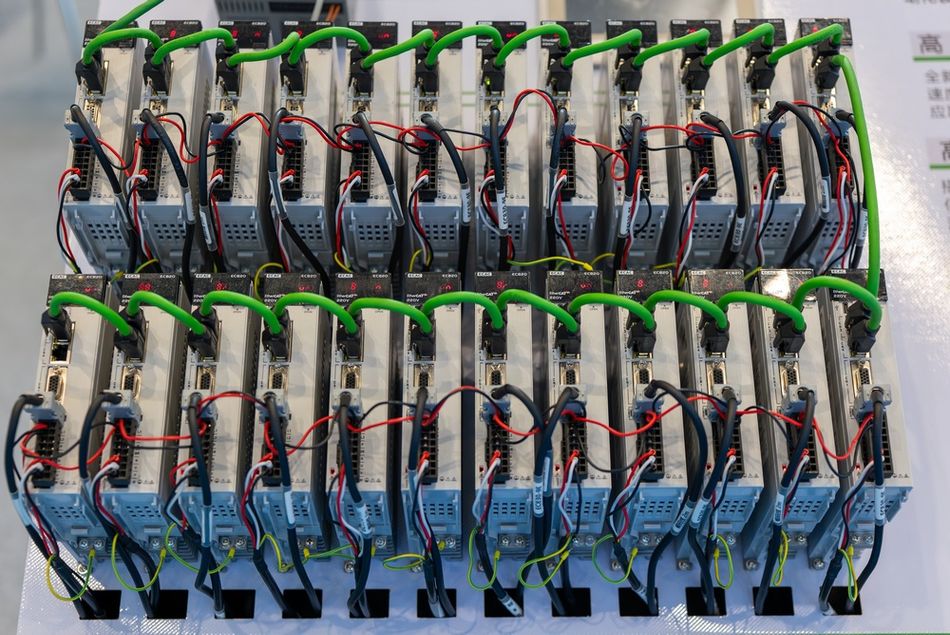
The limitations are resolution and susceptibility to analog error. With a 9-bit analog input and a 6,000 rpm maximum, each least significant bit is about 11.7 rpm, which is coarse for smooth low-speed positioning. [2] This is a large part of why digital fieldbus command has displaced analog on new machines.
CiA 402: The Profile that Makes Drives Interchangeable
CANopen defines the CiA 402 device profile for drives and motion control. It standardizes a finite state automaton, the operation modes, and the parameters, and it is partially standardized in IEC: CiA 402-2 corresponds to IEC 61800-7-201 and CiA 402-3 to IEC 61800-7-301.
The drive state determines which commands it accepts and whether it applies high power. The controlword and command values are mapped into receive PDOs, and the statusword and actual values into transmit PDOs.
The profile fixes object addressing, which is the practical payoff. Indices 6000h to 67FEh are specified by CiA 402, so position, velocity, and torque setpoints live at the same addresses regardless of manufacturer, and the controlword is index 6040h. [6]
The cyclic synchronous modes matter most for coordinated motion. IEC 61800-7-201 introduced cyclic synchronous position, velocity, and torque, in which the host controller runs the trajectory generator and sends a fresh setpoint every cycle while the drive simply follows it.
Synchronization: Distributed Clocks Versus Time Protocols
EtherCAT processes data on the fly as the frame passes each node, supports cycle times of 100 microseconds or less, and synchronizes distributed clocks to well under 1 microsecond of each other.
The drive vendors treat about 1 microsecond as adequate synchronicity for drive technology, with typical cyclic position cycle times between 1 and 4 milliseconds and configurable control-unit cycles from 62 microseconds upward.
In a laboratory study of two BLDC servo drives on EtherCAT with distributed clock synchronization, the difference between the SYNC0 signals of the two drives was 730 nanoseconds in the best case and 831.5 nanoseconds in the worst, across 1,000 measurements at 500-microsecond and 1,000-microsecond cycles. [6]
The same study makes a point worth remembering during commissioning: synchronous operation was influenced less by the distributed clock mechanism itself than by how each drive implemented the application layer of the stack. Two drives on the same network can be timed differently because of firmware, not wiring.
EtherNet/IP takes a different route to the same goal. CIP Sync is compliant with IEEE 1588 and allows synchronization accuracy between two devices of under 100 nanoseconds, which is what makes time-based coordination of distributed axes practical on standard switched Ethernet.
| Integration | Sync Mechanism | Stated Timing | Drive Profile |
| EtherCAT | Distributed Clocks, SYNC0 Event | Cycle ≤ 100 microseconds, Jitter under 1 microsecond | CoE (CiA 402) or SoE |
| CANopen | SYNC Object on a CAN Bus | Limited by CAN Bit Rate, Milliseconds | CiA 402 Natively |
| EtherNet/IP | CIP Sync, IEEE 1588 PTP | Under 100 Nanoseconds between Two Devices | CIP Motion |
| Analog ±10 V | None, Continuous Signal | Set by Controller Update Rate | Not Applicable |
Recommended Reading: Industrial Communication Protection for RS-485 and Ethernet
Servo Drive Versus VFD
Both are power converters that drive a motor, so the confusion is understandable, but the control problem is different. VFD regulates voltage and frequency to set speed, usually without shaft feedback. On the other hand, a servo drive regulates current against measured rotor position, so it corrects error within the loop rather than assuming the motor followed.
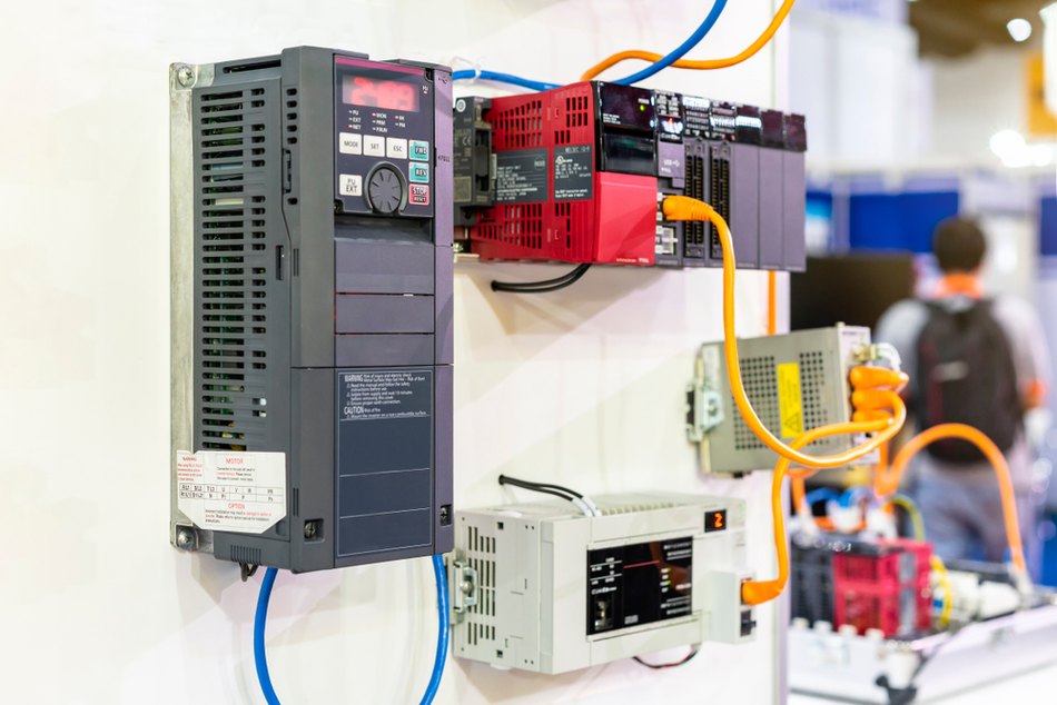
Let’s go through the difference in detail:
| Aspect | Servo Drive | Variable Frequency Drive (VFD) |
| Feedback | Encoder or Resolver Mandatory for Full Performance | Often Sensorless, Feedback Optional |
| Loops Closed | Current, Velocity, and often Position | Typically Speed, using V/Hz or Vector Control |
| Motor Type | Permanent Magnet Servo Motor, Linear Motor, or Induction Servo Motor | Standard AC Induction Motor |
| Best Fit | Positioning, Coordinated Multi-Axis Motion, Robotics, CNC | Fans, Pumps, Conveyors, Continuous Speed Control |
| Cost Driver | Feedback Path, Loop Performance, Fieldbus | Power Rating |
The practical selection rule: if the machine needs to be at a commanded position at a commanded instant, you need a servo drive. If it needs to turn at roughly the right speed, a VFD is usually the cheaper correct answer.
Sizing a Servo Drive
Sizing a drive is separate from sizing the motor. The motor sets the torque and speed; the drive has to supply the current that torque implies, survive the bus voltage, and dissipate the energy the load returns.
Match Continuous and Peak Current to the Duty Cycle: Servo drives are rated in both. Continuous rating covers the RMS current of the move profile; the peak rating covers acceleration transients and is only available for a limited time.
Check the Bus Voltage against Motor Back EMF at Maximum Speed: A drive that cannot maintain headroom above back EMF will not reach the rated speed under load.
Size the Regeneration Path from Energy, Not Power: Start with the total mechanical energy (kinetic plus potential), including motor, gearbox, and load inertia.
Compute the Shunt Resistor for both Average and Peak: Average power is the mechanical energy multiplied by the maximum number of braking cycles per second, and peak power is the greater of the energy divided by the deceleration time or the square of the maximum supply voltage divided by the resistance.
Keep the Shunt Activation Voltage above the Nominal Supply Voltage: The resistor does not switch in during normal operation.
Constrain the Inertia Ratio: The reflected load inertia divided by rotor inertia determines whether the loops can be tuned stiffly at all.
Check the Multi-Axis Bus: In a multi-axis topology, one converter feeds several output sections, so the shared bus must handle the continuous and peak current of every axis together.
Kinetic energy scales with the square of speed, following E = ½Jω², and winding resistance typically absorbs only 10% to 20% of that total in high-efficiency motors, so the rest has to go somewhere.
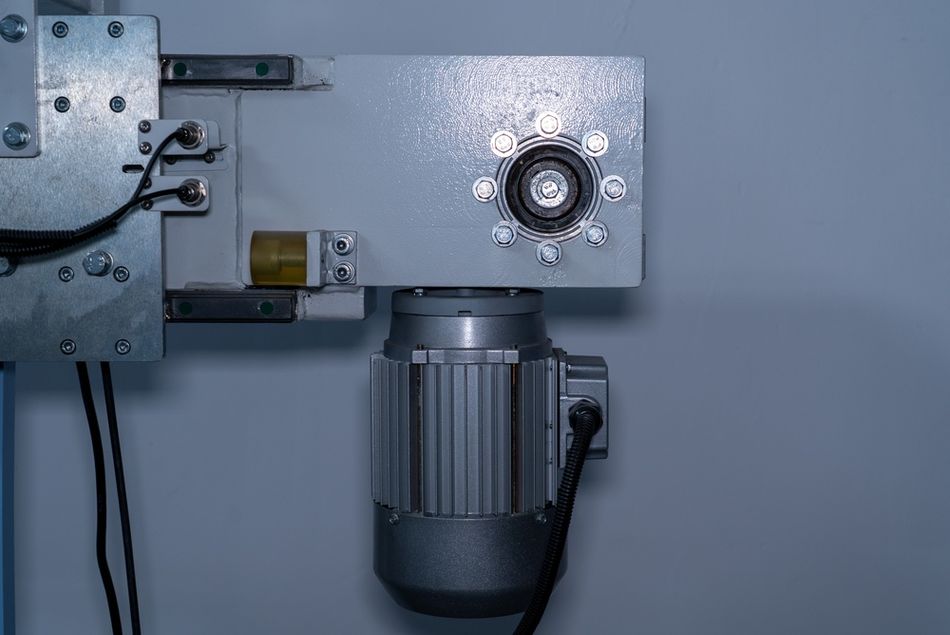
The applications regenerating more than a few kilowatt-hours per shift generally justify an active regenerative front end instead of dissipating the energy as heat.
Recommended Reading: What is a CAN Bus: The Backbone of Modern Vehicle Communication
Servo Drive Commissioning Workflow
Commissioning should establish correct motor, feedback, and safety behavior before aggressive tuning begins. The structured sequence reduces the risk of unstable motion, incorrect commutation, excessive current, or mechanical damage.
Identify the Motor: Enter or automatically detect the motor's rated voltage, current, torque, speed, pole count, and electrical parameters. Where supported, use the manufacturer's electronic motor identification data rather than manually entering values.
Configure the Feedback Device: Select the encoder or resolver type, resolution, communication format, and polarity. The drive must correctly interpret rotor position to perform accurate commutation and closed-loop control.
Verify Motor Direction: Jog the axis slowly and confirm that commanded direction, motor rotation, and encoder feedback all agree. Reversed feedback can cause immediate instability when you enable the loop.
Set Current and Motion Limits: Configure continuous and peak current, maximum velocity, acceleration, deceleration, travel limits, and following-error thresholds before running full-speed moves.
Perform a Basic Motion Test: Run the axis at low speed and acceleration to verify smooth rotation, correct feedback, braking behavior, limit switches, and fieldbus commands.
Run Auto-Tuning: Once basic operation is stable, allow the drive to estimate load inertia and calculate initial current, velocity, and position-loop gains.
Suppress Mechanical Resonance: Use frequency-response tools, drive traces, or vibration measurements to identify resonances. Apply notch or low-pass filters where necessary before increasing gains further.
Optimize the Final Gains: Increase velocity and position gains gradually while monitoring overshoot, settling time, following error, current demand, and vibration. The goal is the highest useful bandwidth without sacrificing stability or mechanical life.
The commissioning sequence is therefore best treated as verification first, tuning second. A poorly configured feedback path or incorrect motor data cannot be fixed with higher gains; you must resolve those fundamental errors before performance optimisation begins.
Recommended Reading: Low Pass Filter vs High Pass Filter – Theory, Design, and Applications
Tuning a Servo Drive
Modern drives start with auto-tuning, which estimates machine inertia in real time and writes the corresponding gains. If the result is unsatisfactory, move through progressively more manual gain-adjustment modes and finally to fully manual tuning.Typical manufacturer requirements include running the tuning move at about 200 rpm or higher, with around 500 rpm preferred, and repeatedly moving the axis forward and backwards through sufficiently fast positioning cycles.
Extremely high load-to-motor inertia ratios are another common problem. Ratios above roughly 50:1 can prevent some auto-tuning algorithms from identifying the system reliably. In such cases, you may need to increase gear reduction, select a motor with greater rotor inertia, or otherwise reduce reflected inertia.
The mechanical resonance usually determines how high the control gains can ultimately be raised. Flexible couplings, belts, gearboxes, machine frames, and long mechanical structures can introduce resonant frequencies that become unstable as servo bandwidth increases.
Production drives therefore provide tools such as notch filters, resonance low-pass filters, and low-frequency vibration suppression. The typical process is to identify the dominant resonance, attenuate it with an appropriately placed notch filter, and then increase velocity and position gains until you achieve the required responsiveness without excessive vibration or following error.
Servo tuning should therefore be treated as part of machine commissioning, not a final checkbox. Simple rigid axes may tune quickly, while flexible or highly dynamic mechanisms may require repeated testing, filtering, and gain adjustment to balance response, stability, vibration, and accuracy.
Functional Safety: STO and the Rest
Safe Torque Off is a hardware function that prevents the drive from generating torque by cutting the pulses to the power semiconductors in the inverter, while logic and communication stay powered. Because the drive stays alive, the machine recovers in milliseconds rather than waiting through a full power-up.
The governing standard is IEC 61800-5-2. It sets requirements for the design, development, integration, and validation of safety-related power drive systems within the IEC 61508 framework. Its scope is bounded at SIL 3, so a drive-based safety sub-function cannot be claimed above that level.
Drives certified to PL e or SIL 3 use fully redundant, deterministic internal safety circuitry so that a single hardware failure does not cause a dangerous loss of the safety function. STO can be triggered by hardwired dual-channel safety inputs or over a safety-rated network such as Fail Safe over EtherCAT, which allows a synchronized response across many axes.
Safe Stop 1 brakes along a monitored ramp and then applies STO at standstill, and Safely Limited Speed monitors speed and drops to a safe state if a limit is exceeded. Both are defined in the same IEC 61800-5-2 family.
One design note that trips people up: STO removes torque; it does not hold a load. On a vertical axis, you still need a mechanical brake, because a suspended mass will fall the moment torque disappears.
EMC and Installation
The servo drive is a fast-switching power converter with a long cable to a motor, which makes it an efficient antenna. IEC 61800-3, Edition 4.0, published in 2022, is the EMC product standard for adjustable-speed power drive systems and machine tools, covering input and output voltages up to 35 kV AC RMS at all power ratings. [8] Conformity is assessed against equipment categories, commonly written C1 through C4, which pair the intended environment (residential versus industrial) with how the drive reaches the market. The applicable category drives filter selection and the maximum shielded cable length you are allowed.
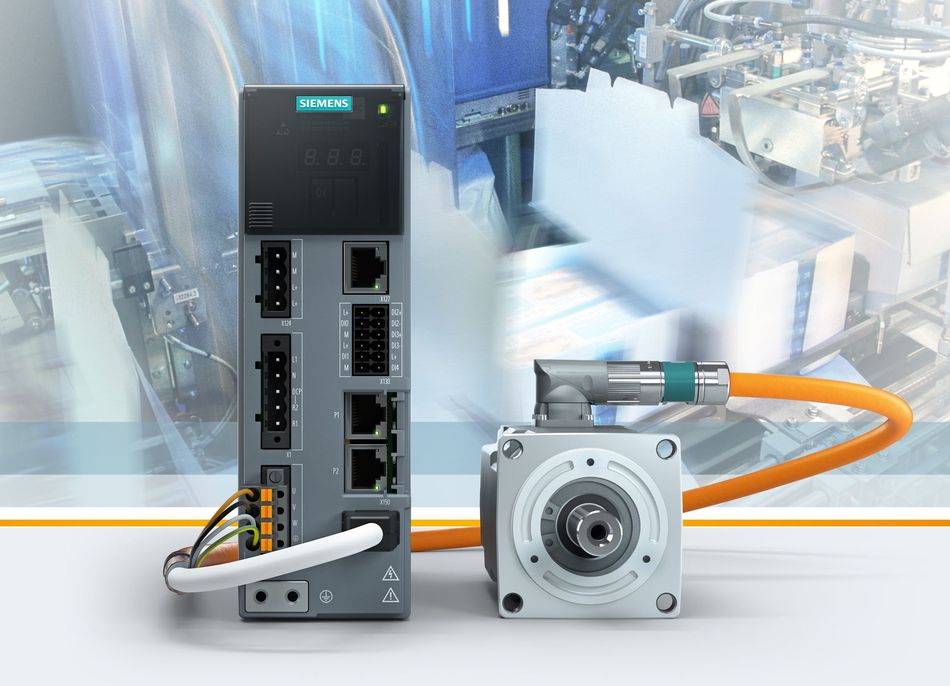
In practice, this means the shielded motor cable is part of the drive, not an accessory. Shield bonding at both ends, separating power and feedback routing, and selecting the correct filter keep encoder counts clean and the installation compliant.
Recommended Reading: Ensuring EMC Through A Validation Ecosystem: Anechoic Chambers, Motor Bench, and Advanced Simulation
Common Mistakes and Troubleshooting
Blaming the Drive for a Mechanical Resonance: If gains oscillate at a repeatable frequency, notch that frequency before increasing gain further.
Ignoring the Inertia Ratio: Above roughly 50:1, the auto-tuner may simply fail, and manual tuning will be fragile.
Sizing the Shunt: Forgetting the average and overlooking the peak, or the reverse. Both ratings are independent constraints.
Assuming Distributed Clocks Guarantee Identical Timing: Application-layer implementation in each drive affects real synchronization.
Overshooting on Carrier Frequency: More carrier means more switching loss and more heat; for bandwidth, you may be able to get through faster loop computation instead.
Expecting a Resolver to Feed a High-Bandwidth Velocity Loop: The converter, not the resolver, is the bottleneck.
Recommended Reading: Stepper vs Servo Motors: Mastering Motor Selection for Precision Engineering
Conclusion
The servo drive is best understood as three layers stacked on each other: a power stage that can source and sink current, a set of nested servo loops whose performance is capped by the current loop, and a communication interface that decides how tightly the drive can be coordinated with other axes.
Get the current loop and the feedback path right, and the rest of the system has room to perform. Get the sizing, the regeneration path, and the inertia ratio right, and the machine will still be running the profile you commissioned a year later.
Frequently Asked Questions
Q. How does a servo drive work?
A. It takes a command signal from a controller, compares it against feedback signals from the motor's encoder or resolver, and switches the DC bus through a transistor bridge to deliver exactly the current needed to close the error. That comparison and correction repeat every loop cycle, historically every 250 microseconds to 2 milliseconds.
Q. What is the difference between a servo drive and a servo motor?
A. The motor converts electrical energy into mechanical motion. The drive is the electronic device that supplies and regulates that energy. Neither works as a servomechanism without the other and without a feedback device.
Q. Is a servo drive the same as a servo amplifier?
A. Yes. The terms are used interchangeably for the electronic amplifier that powers a servomechanism.
Q. Can a servo drive run a stepper motor?
A. The commercial drives commonly support two-phase and three-phase stepper motors, along with brushed, brushless, and linear motors. Running stepper motors closed-loop from a servo drive gives you position verification that open-loop stepping cannot provide.
Q. What is CiA 402 and why does it matter?
A. It is the CANopen device profile for drives and motion control, standardized as IEC 61800-7-201. It defines the state machine, operation modes, and object addresses, so a compliant drive presents the same interface regardless of vendor.
Q. How many axes can run in tandem on one network?
A. EtherCAT addresses up to 65,535 nodes per segment, though the practical number is set by cycle time, process data payload, and master performance. Two drives working in tandem on a gantry is a far more common case than the theoretical maximum.
Q. Does Safe Torque Off remove power from the drive?
A. No. STO blocks the pulses that reach the inverter's power semiconductors while the drive's logic and communication remain powered.
Q. What feedback device should I use for a high-bandwidth application?
A. Encoder, in most cases. Resolver-to-digital conversion caps feedback bandwidth at roughly 53 Hz to under 100 Hz depending on resolution, while an encoder introduces no conversion dynamics into the loop. Resolvers remain the better choice above 125 degrees Celsius and in severe environments.
References
[1] FESTO. Servo Drive: How Does a Servo Drive Work? [Cited 2026 August 20] Available at: Link
[2] EASA. Tech Note 45 - Servo Drives [Cited 2026 August 20] Available at: Link
[3] ELMO. DC Bus in Servo Drive Solutions Explained [Cited 2026 August 20] Available at: Link
[4] TI. Faster Current Loop Pays Off in Servo Motor Control [Cited 2026 August 20] Available at: Link
[5] HEIDENHAIN. Resolvers vs Encoders for Motion Control [Cited 2026 August 20] Available at: Link
[6] MDPI. Synchronization of Electrical Drives via EtherCAT Fieldbus Communication Modules [Cited 2026 August 20] Available at: Link
[7] IEC. IEC 61800-5-2:2016, Safety requirements, Functional [Cited 2026 August 20] Available at: Link
[8] IEC. IEC 61800-3:2022, EMC Requirements and Specific Test Methods for PDS and Machine Tools [Cited 2026 August 20] Available at: Link
in this article
1. Key Takeaways2. Introduction3. What a Servo Drive Actually Does?4. Inside the Drive: The Power Stage5. The Servo Loops6. Feedback Devices and Sensors7. Fieldbus Interfaces: EtherCAT, CANopen, and EtherNet/IP8. Servo Drive Versus VFD9. Sizing a Servo Drive10. Servo Drive Commissioning Workflow 11. Tuning a Servo Drive12. Functional Safety: STO and the Rest13. EMC and Installation14. Common Mistakes and Troubleshooting15. Conclusion16. Frequently Asked Questions17. References