Servo Motor: How It Works, Types, Specifications, and Sizing
This article explains how a servo motor works, its construction, control loops, encoder and resolver feedback, AC and DC types, sizing math, and tuning fixes.

22 Aug, 2026. 18 minutes read
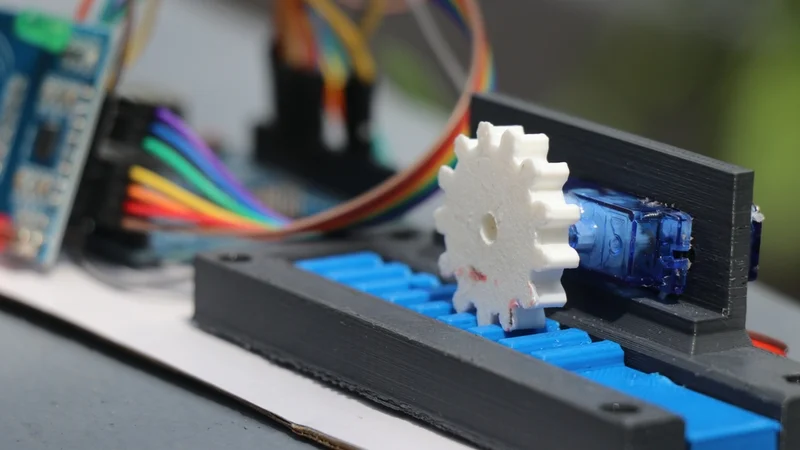
3D-Printed Gear attached to the Shaft of a Micro Servo Motor
Key Takeaways
System Definition – The servo motor is a closed-loop rotary actuator that combines a motor, feedback sensor, controller, and gearing to continuously monitor position and deliver precise control of angular position, velocity, and acceleration.
BLDC/PMSM Stator Commutation – Industrial servo motors are usually brushless permanent magnet motors: a wound stator surrounds a magnet rotor, and the drive commutates the stator currents based on the measured rotor angle.
Cascaded Control Architecture – Control is a cascade: a current loop inside a velocity loop inside a position loop, with each inner loop 5 to 10 times faster than the one outside it.
Inertia and Resonance Bandwidth – The inertia ratio between load and rotor, together with coupling stiffness, sets the resonance frequencies that cap usable bandwidth; torque alone does not buy performance.
Thermal and Dynamic Sizing – Sizing is both a thermal and dynamic problem: RMS torque must stay within the continuous zone, peak torque must cover acceleration, and the inertia ratio must let you tune the loop.
What Is a Servo Motor?
The servo motor is a precision electromechanical actuator designed for applications that demand controlled position, speed, and torque. Unlike conventional motors that simply rotate when power is applied, a servo motor operates as part of a closed-loop control system, continuously using feedback to compare actual motion with the commanded target. This ability to detect and correct error gives servo systems their characteristic accuracy, responsiveness, and repeatability.
Depending on the application, servo technology may use AC or DC motors, rotary or linear configurations, and different feedback devices, control modes, and transmission arrangements. Selecting the right servo motor therefore requires more than matching power or rotational speed; engineers must consider torque, inertia, duty cycle, acceleration, operating voltage, encoder resolution, environmental conditions, and mechanical loading.
This article explains how a servo motor works, examines its major types and specifications, and provides practical guidance for sizing a motor correctly for modern industrial motion-control applications.
Inside a Servo Motor: Construction
The most common industrial servomotors are based on brushless motors. The rotor carries a powerful permanent magnet, and the stator is composed of multiple conductor coils. The rotor spins when the coils are energized in the specified order, and rotor movement is determined by the frequency, phase, polarity, and current in the stator.
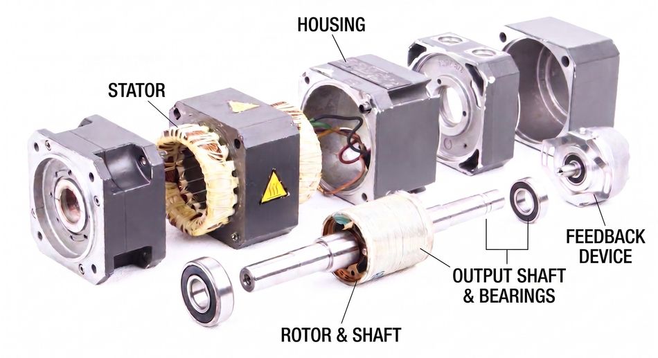
The practical construction breaks down into five parts:
Stator: Laminated iron teeth carrying three-phase windings. Energizing the stator coils in sequence creates a rotating magnetic field that the rotor follows. Winding geometry is a design lever: Yaskawa states that advanced magnetic circuitry and optimized winding geometry deliver very low cogging torque in its SGM7J rotary servo motors. [1]
Rotor: For permanent magnet motors, high-flux magnets are bonded or embedded in a steel core. The same Yaskawa series uses neodymium iron boron magnets with high flux density to reduce rotor size, lower rotor inertia, and improve acceleration.
Feedback Device: The encoder or resolver on the non-drive end, supplying position feedback to the drive.
Output Shaft and Bearings: Often with an optional holding brake and shaft seal, since a vertical axis has to stay put when power is removed.
Housing and Thermal Path: Ingress protection and heat rejection define the continuous rating. The SGM7J is rated IP67 for dust and washdown and is specified to run 20% cooler than the previous generation.
The power stage is not inside the motor. The amplifier, current sensing, and control loops live in the servo drive. The basic operating principle of the drive is the same as an inverter: converting AC power to DC and back to a controlled frequency, with the added jobs of reading encoder feedback, real-time closed-loop adjustment, communication with the motion controller, and I/O processing for safety components and status signals.
Recommended Reading: Motor Speed Control: Methods Across Motor Types
How the Closed Loop Works?
The servo system feeds back the actual position, speed, or torque, compares it to the command, calculates the error, and corrects it in real time.
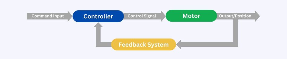
That cycle of feedback, error detection, and correction is closed-loop control, and the position, speed, and torque loops run independently depending on the application.
The Cascade: Current, Velocity, Position
The servo drives use a nested structure with the current loop inside the velocity loop inside the position loop. [2]
Current Loop - also called the torque loop, is the innermost and fastest control loop. Because motor torque is approximately proportional to current, the drive regulates phase current to produce the torque the velocity controller requests. It typically uses a PI controller, with the drive manufacturer setting most parameters.
Velocity Loop - forms the middle layer. It compares the commanded motor speed with speed calculated from encoder feedback and adjusts the torque command sent to the current loop. Proportional and integral gains determine how quickly the motor responds to speed errors and how effectively it removes steady-state error.
Position Loop - is the outermost layer. It compares the commanded position with the measured position and converts the resulting following error into a velocity command. In a conventional cascaded architecture, this loop commonly uses proportional control because the inner velocity loop already provides damping and disturbance rejection.
The bandwidth hierarchy is not optional. The general rule is that the velocity loop should have a bandwidth 5 to 10 times that of the position loop, and the current loop 5 to 10 times that of the velocity loop. Raising the bandwidth of an outer loop past what the next inner loop can support gains you nothing.
The position loop can run without a velocity loop; in that case, it becomes a PID controller rather than a proportional one, but velocity feedback adds stiffness and rejects high-frequency disturbances.
Commutation and Field-Oriented Control
Torque in a three-phase motor depends on where the current sits relative to the rotor field. Current applied in phase with the rotor magnetic field produces no torque, while orthogonal current does, which is why field-oriented control (FOC) uses orthogonal applied current and real-time rotor position to drive the motor. [3]
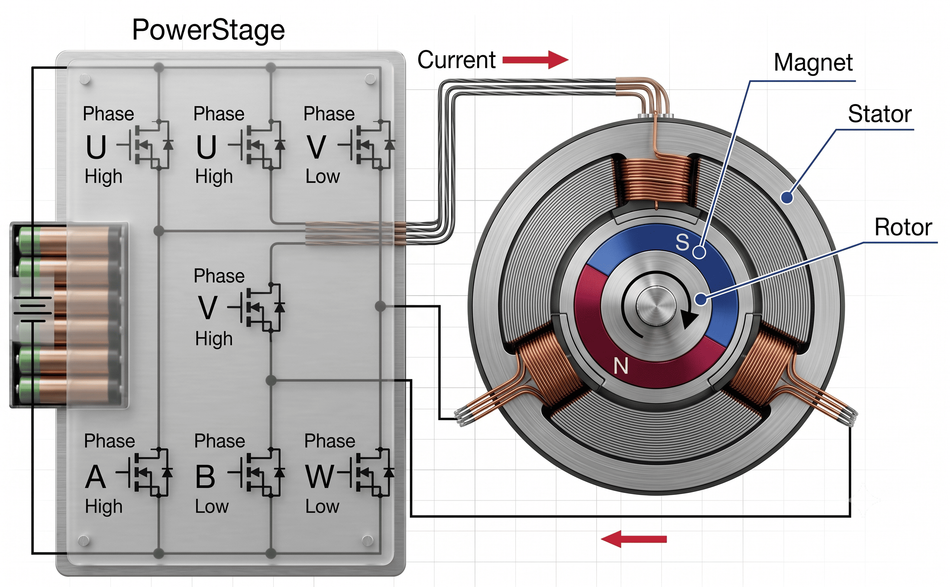
FOC, also called vector control, applies the Clarke and Park transforms to convert measured phase currents from stator-fixed coordinates into field-synchronous coordinates. That yields two components: Iq, controlled by one PI controller to set torque, and Id, controlled by another to set magnetic flux. Because the flux comes mostly from the rotor magnets, the Id target is normally zero.
Here, two consequences matter in practice. First, FOC needs rotor angle, taken from an encoder or more coarsely from Hall sensors. Second, because velocity sensors are uncommon, velocity is usually computed by differentiating the position signal, which is why encoder resolution and noise directly affect velocity-loop quality.
Semi-Closed versus Fully Closed Loop
The mounting location of the feedback sensor directly dictates which errors the control loop can detect and correct.
Semi-Closed Loop: The detector sits behind the motor and infers table position from shaft rotation, so the position feedback describes the motor rather than the workpiece. This is the common arrangement. Ball screw pitch error and gear backlash still need compensation, and screw torsion and thermal expansion still show up as errors.
Fully Closed Loop: The linear encoder reads the machine element position directly and compares it to the target. It is the most reliable form of closed loop, and it removes the need to compensate for backlash, feed screw pitch error, torsion, and expansion.
Beyond higher expenses, fully closed-loop control complicates system tuning, as every flexible element connecting the rotor to the linear scale becomes part of the feedback loop.
Recommended Reading: Field Oriented Control (FOC) for AC Motors
Feedback Devices: Encoders, Resolvers, and Potentiometers
The feedback device determines how precisely a servo system can measure motion and therefore places a fundamental limit on position and velocity control. Industrial servo systems primarily use incremental encoders, absolute encoders, and resolvers, while potentiometers remain common in simpler hobby and RC servo applications.
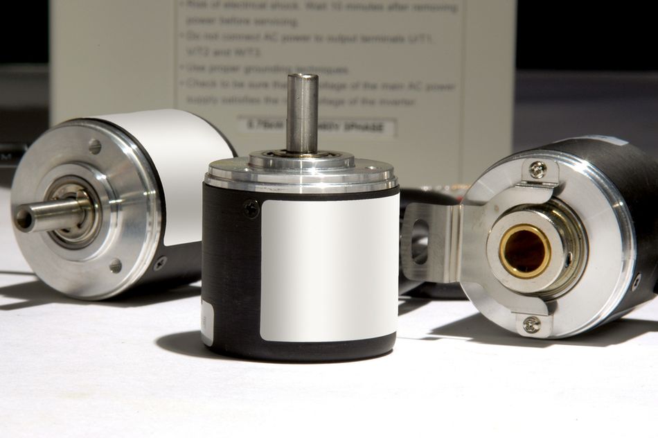
Incremental Encoder: Generates a stream of quadrature pulses as the shaft rotates, typically accompanied by an index pulse marking one reference position per revolution. The controller determines position by counting these pulses. Because the count is lost when power is removed, an incremental system normally requires a homing sequence at startup. This makes incremental feedback economical and effective for machines where returning to a reference switch is acceptable.
Absolute Encoder: Assigns a unique digital position value to each measurable shaft angle. The single-turn absolute encoder identifies the angular position within one revolution but does not inherently track how many complete revolutions have occurred.
Multi-Turn Absolute Encoder: Records both shaft angle and revolution count, so the full axis position remains available immediately after power-up. This capability makes multi-turn feedback particularly valuable in industrial robots, CNC machines, packaging equipment, and ball-screw-driven axes where rehoming could interrupt production or create positioning problems.
Resolver: Uses analog sine and cosine windings to determine rotor angle. Its effective resolution depends largely on the resolver-to-digital conversion electronics in the servo drive. Resolvers are extremely robust and tolerate high temperatures, vibration, shock, contamination, and radiation, making them suitable for demanding industrial, aerospace, and automotive environments.
Potentiometer: Provides absolute position through a voltage generated by a moving wiper. It is inexpensive and simple but suffers from limited resolution, electrical noise, mechanical wear, and restricted lifetime. Consequently, potentiometers are generally reserved for low-cost servos rather than precision industrial motion systems.
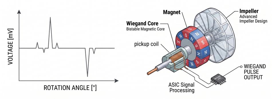
Multi-turn tracking can be implemented in several ways. Battery-backed systems maintain an electronic revolution counter while power is removed. Mechanical designs use geared code discs to record turns without external power, while newer gearless systems can use Wiegand-effect sensors, which generate enough electrical energy from changes in a magnetic field to update an internal turn counter. [4]
The practical argument for multi-turn absolute feedback is recovery. In a coordinated multi-axis machine, rehoming after a power failure and returning to the prior position within fine tolerance is nearly impossible, so the axis needs to know where it is the moment it powers up.
Resolution is worth putting in numbers. The 24-bit encoder, as fitted to the Yaskawa series above, resolves 16,777,216 counts per revolution, which is about 0.077 arc seconds per count. That is far finer than any mechanical element in a typical machine, and the point is not accuracy at that scale but a clean, low-noise velocity signal for the loop.
Recommended Reading: What is an Encoder: Understanding the Basics and Beyond
Types of Servo Motors
Servo motors can be classified by motor construction, commutation method, and the type of motion they produce. The main categories are AC synchronous servos, AC asynchronous servos, brushed DC servos, brushless DC servos, linear servo motors, and hobby or RC servos.
AC Servo Motors
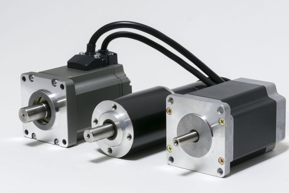
Modern industrial AC servo motors are predominantly permanent magnet synchronous motors (PMSMs). Their stator windings generate a rotating magnetic field, while permanent magnets on the rotor remain synchronized with that field. Electronic commutation uses encoder or resolver feedback to determine rotor position and regulate torque accurately.
The Yaskawa SGM7J family illustrates the class: 50 W to 1.5 kW, medium inertia, rated speed 3,000 rpm with a maximum of 6,000 rpm, torque ratings up to 2.39 N.m, and peak acceleration torque up to 300% of rated torque held for up to three seconds. [1]
AC synchronous servos are widely used in robotics, CNC machinery, packaging systems, semiconductor equipment, and other high-performance motion axes. Depending on the design, ratings can range from tens of watts to tens of kilowatts.
One important characteristic is their short-term overload capability. Many industrial servos can produce two to three times their rated torque during acceleration for a limited period. This allows engineers to select the motor around its continuous RMS thermal requirement while still supplying the peak torque needed for rapid acceleration and deceleration.
Asynchronous AC servo motors use a squirrel-cage induction rotor rather than permanent magnets. Vector control regulates magnetic flux and slip to achieve servo-level speed and torque control. Although they generally offer lower torque density than PMSMs, their broad field-weakening capability makes them useful for high-power machine-tool spindles and applications requiring wide constant-power speed ranges.
DC Servo Motors
The brushed DC servo motor uses mechanical brushes and a commutator to switch current through the rotor windings. Torque is approximately proportional to armature current, making control comparatively straightforward. Combined with an encoder or potentiometer, these motors can provide accurate closed-loop motion using relatively simple electronics.
Their main disadvantage is mechanical wear. Brushes require periodic replacement, generate electrical noise, and limit maximum speed and continuous-duty capability. As a result, brushed servos are now found mainly in legacy machinery and simpler motion-control systems.
The brushless DC (BLDC) servo motor replaces mechanical commutation with electronic switching. BLDC servos commonly use permanent-magnet rotors and Hall sensors or encoders for rotor-position feedback. They provide higher reliability, lower maintenance, and better power density than brushed designs. This makes them suitable for mobile robots, aerospace actuators, automated equipment, and compact motion systems. The research on hybrid actuation for more electric aircraft describes an electromechanical actuator as a brushless DC motor, a gearbox, and a ballscrew actuator driving a flight control surface. [5]
Linear Servo Motors
The linear servo motor can be viewed as a rotary permanent-magnet motor opened out into a straight line. The stator becomes a coil assembly, and the rotor becomes a permanent-magnet track. Because force acts directly on the moving element, it requires no ball screw, belt, or gearbox.
Eliminating mechanical transmission reduces backlash and enables very high acceleration, speed, and positioning precision. Linear servos are therefore common in semiconductor manufacturing, precision stages, machine tools, and high-speed automation.
Hobby and RC Servos
Hobby servos combine a small DC motor, reduction gearbox, potentiometer, and control electronics in one compact package. The three-wire connection provides power, ground, and the command signal.
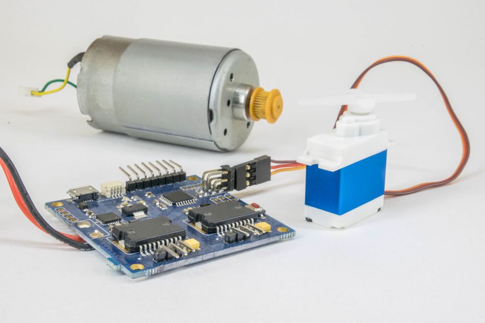
The standard versions typically control angular position over roughly 180 degrees, while continuous-rotation versions control speed and direction instead. Unlike industrial servo systems, these devices integrate the drive electronics and feedback mechanism inside the housing. They are inexpensive and convenient for models, educational systems, and light robotics, but their accuracy, durability, torque control, and feedback capabilities fall far short of industrial servo motors.
Recommended Reading: Types of Industrial Control Systems: Examples and Applications
Servo Motor vs Stepper Motor
Servo motors and stepper motors can both provide precise motion, but they achieve it through fundamentally different operating principles.
| Criterion | Servo Motor | Stepper Motor |
| Pole Count | Low, roughly 4 to 12 | High, 50 to 100 or More |
| Torque Production | Continuous, Proportional to Current | Discrete, from Phase Excitation Patterns |
| Feedback | Integral to Operation, High-Bandwidth Current Loop | Optional, added to Catch Missed Steps |
| Behavior at Speed | Usable Torque across a Wide Speed Range | Torque Falls Off, Resonance and Ripple Appear |
| Commissioning | Requires Tuning against Resonance & Compliance | Simpler in Stiff, Predictable Mechanics |
| Cost | Higher, Motor + Feedback + Drive | Lower |
The comparison of closed-loop steppers and servos frames the choice well: a closed-loop stepper adds an encoder so the motor driver can adjust commanded current and stop losing steps, but it keeps stepper physics, including torque ripple and resonance at certain speeds. [6] The servo relies on that feedback from the start and delivers smoother motion, higher usable acceleration, and better behavior under rapidly changing loads.
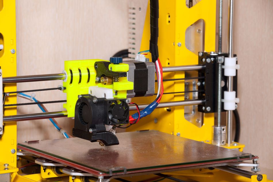
For cost-sensitive positioning at low to moderate speeds with predictable loads, a stepper motor is often sufficient. The closed-loop stepper adds protection against missed steps where additional reliability is required. On the other hand, a servo motor becomes the stronger choice for high continuous speeds, rapid acceleration, changing or unpredictable loads, high dynamic accuracy, and applications requiring minimal vibration and smooth motion.
Recommended Reading: Stepper vs Servo Motors: Mastering Motor Selection for Precision Engineering
Sizing an Industrial Servo Motor
The servo motor sizing comes down to two torque calculations and one inertia check:
1. Acceleration Torque: The torque required to accelerate the combined motor and reflected load inertia is:
Ta = (JL + J0) × α
where JL is the reflected load inertia, JM is the motor rotor inertia, and α is angular acceleration in rad/s².
2. RMS Torque: Because a servo cycle mixes acceleration, constant speed, deceleration, and dwell, the thermally relevant number is the time-weighted RMS value:
Trms = √( (Ta² × t1 + Tl² × t2) / (t1 + t2 + t3) )
The calculated RMS torque must remain within the motor's continuous torque rating. A practical design margin is often applied rather than operating continuously at the limit. Peak acceleration and deceleration torque must also remain within the motor's intermittent or peak-torque envelope. This is where a servo capable of producing roughly 300% rated torque for a few seconds provides an important advantage.
3. Inertia Ratio: The final check compares the reflected load inertia with motor rotor inertia:
Inertia Ratio = JL / JM
Rules of thumb such as 10:1, 5:1, or 1:1 are useful starting points, but no ratio is universally acceptable. The usable value depends on drivetrain stiffness, coupling compliance, controller bandwidth, resonance, and the required dynamic response. The motor may have enough torque to accelerate the load but still produce an unstable or poorly controlled axis if the inertia mismatch is excessive.
Why the Inertia Ratio Governs Bandwidth?
Model the coupling as a spring of constant Ks between rotor inertia JM and load inertia JL. That two-mass system has an anti-resonance and a resonance whose frequencies depend on both stiffness and the inertia split.
At anti-resonance, the load moves with equal and opposite torque to the motor; the two are 180 degrees out of phase, and the rotor can stand still while the load oscillates. Since most designs mount feedback only on the motor, the drive can report a healthy axis while the load shakes itself apart.
At resonance, the motor and load exchange energy through the compliant drivetrain, amplifying vibration. Increasing servo gain can then excite the resonance instead of improving response, limiting the maximum achievable control bandwidth.
Reducing the inertia ratio generally decreases the severity of these resonant effects and pushes troublesome frequencies higher, making filtering and tuning easier. A lower ratio therefore allows higher gains, faster settling, and better disturbance rejection. This is why correct servo sizing requires more than satisfying torque and speed requirements: the motor inertia must also be appropriate for the mechanics it is expected to control.
Recommended Reading: Motor Control Design: End-to-End Methodology
Resonance, Filters, and Tuning in Practice
Mechanical resonance splits into two problems, each with a different cure. In Cures for Mechanical Resonance in Industrial Servo Systems, George Ellis separates high-frequency resonance, which causes instability at the mechanical natural frequency of typically 500 to 1,200 Hz, from low-frequency resonance at the first phase crossover, typically 200 to 400 Hz. [7] Low-frequency resonance is the more common case in general industrial machines.
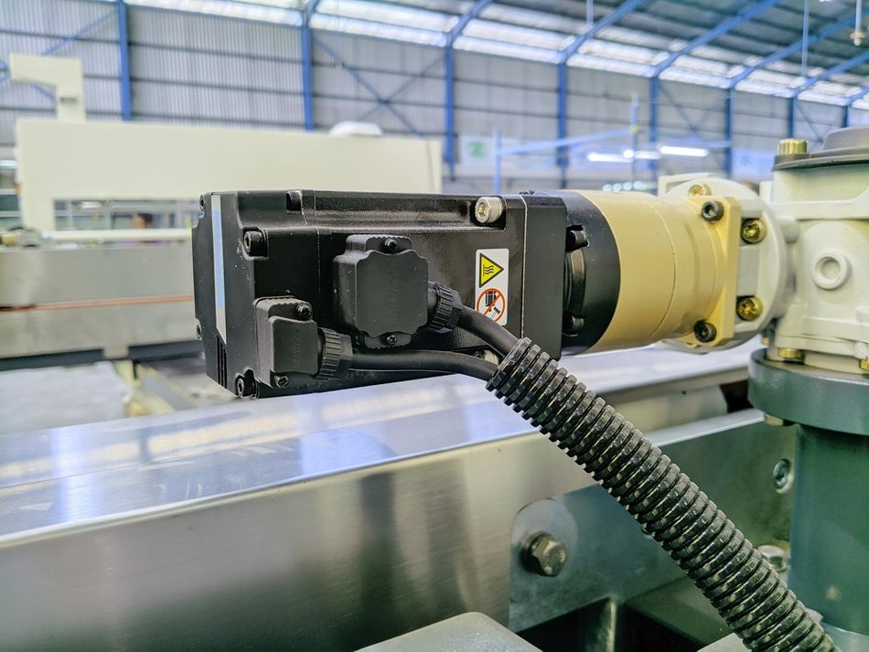
The effect of inertia mismatch can be substantial. Above the resonant frequency, the mechanical load effectively decouples from the motor, leaving the controller to see the rotor inertia primarily. With a 5:1 load-to-motor inertia ratio, the apparent inertia can fall by a factor of six, increasing loop gain by roughly 16 dB. Unless compensated, that increase consumes gain margin and forces the engineer to reduce controller gain, resulting in slower command response and poorer disturbance rejection.
Ellis measured the alternatives on a rig with a 1.8 × 10⁻⁵ kg.m² motor, a 6.3 × 10⁻⁵ kg.m² load, and a 30 N.m/rad coupling, giving a resonance near 230 Hz and an anti-resonance near 110 Hz, with the velocity loop running at 16 kHz:
| Configuration | Closed-Loop Bandwidth | Settling Time |
| Baseline PI, No Filtering | 23 Hz | Nearly 60 ms |
| Single-Pole Low-Pass at 50 Hz | 35 Hz | Nearly 35 ms |
| Bi-Quadratic Filter | 56 Hz | Nearly 22 ms |
| Bi-Quad plus Acceleration Feedback | 77 Hz | Nearly 12 ms |
Filter selection depends on the type of resonance. The notch filter is effective when a narrow, high-frequency resonance peak must be suppressed. It is much less effective against broad low-frequency resonance caused by a compliant drivetrain and large inertia mismatch. Applying a notch filter to the wrong problem can therefore mask symptoms without addressing the mechanical limitation.
The mechanical improvements should generally come before aggressive filtering. Increasing coupling stiffness, reducing reflected inertia through gearing, improving drivetrain rigidity, or selecting a motor with more appropriate rotor inertia can substantially raise achievable bandwidth. Adding rotor inertia can also reduce mismatch, although it sacrifices some acceleration capability.
The direct-drive systems represent the opposite extreme. By eliminating gearboxes, couplings, and ball screws between the motor and load, they greatly increase effective drivetrain stiffness and remove several resonance-producing elements. The result is an axis that can support higher control gains, faster settling, and more precise motion with less dependence on corrective filtering.
Recommended Reading: Direct Drive vs Bowden Extruder for 3D Printing
Interfaces, Networks, and Safety Standards
Servo drives are rarely commanded by analog voltage now. They sit on a fieldbus under a PLC or motion controller and speak a standardized drive profile.
CiA 402 is one of the most widely used device profiles for drives and motion control. It defines a finite-state machine that governs drive behavior through control-word commands and status-word feedback, together with standardized operating modes for position, velocity, and torque control. CiA 402-2 is published as IEC 61800-7-201, while CiA 402-3 corresponds to IEC 61800-7-301. Revisions released in February 2024 added capabilities including 64-bit position values and additional operating modes.
The profile is used across several industrial communication networks, including CANopen, CANopen FD, EtherCAT, and POWERLINK. This common architecture improves interoperability and allows machine builders to change servo-drive vendors without completely redesigning the higher-level motion application.
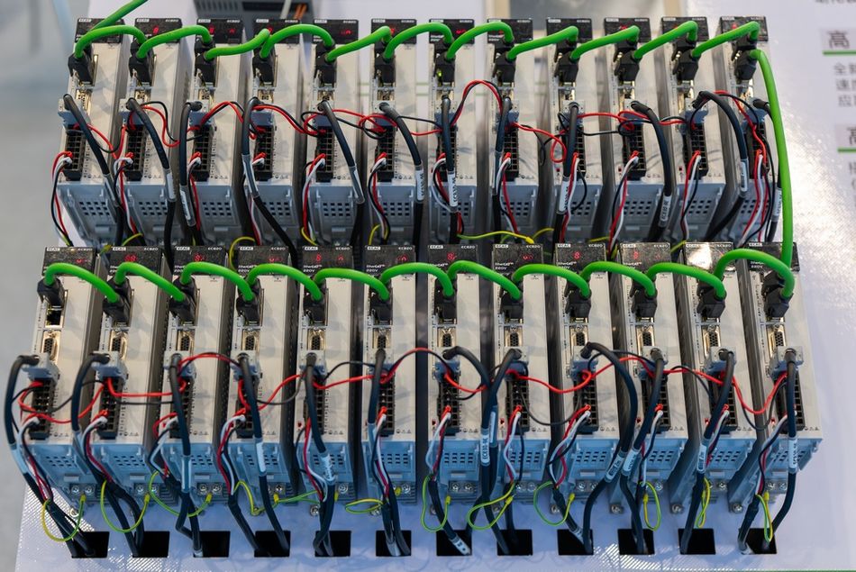
In practical servo systems, these requirements appear as integrated functions such as Safe Torque Off (STO), Safe Stop 1 (SS1), and Safely Limited Speed (SLS). STO prevents the drive from producing motor torque, while SS1 initiates a controlled stop before removing torque. SLS monitors speed and ensures it remains below a defined safe limit.
Integrating these functions directly into the servo drive can reduce reliance on external safety contactors, simplify wiring, and improve diagnostic capability. However, safety certification must still be evaluated at the complete machine level because final safety performance depends on the drive, motor, feedback device, controller, wiring, and overall safety architecture.
Recommended Reading: What Is a Servo Drive? Architecture, Control Loops, Fieldbus, and Sizing
Where Servo Motors Are Used
Servo motors appear across a wide range of industrial applications wherever precise position, speed, torque, or synchronized motion is required.
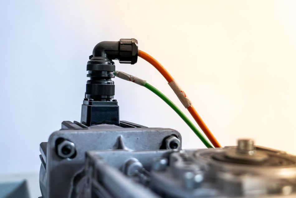
The combination of a motor, feedback device, drive, and control algorithm lets each servo mechanism correct motion continuously rather than simply assume a commanded movement has occurred.
Robots: The articulated industrial robots use one servo axis per joint, with multi-turn absolute feedback so the robot knows its pose at power-up. The collaborative robots add torque sensing on top for force limiting.
Machine Tools and In-Line Manufacturing: Feed axes on mills and lathes are the classic fully closed-loop case, with a linear scale on the table.
Packaging and Converting: Dozens of electronically geared axes replacing line shafts and cams, where synchronization error matters more than absolute accuracy.
3D Printers: Higher-end machines have shifted from open-loop steppers to servo or closed-loop stepper axes to raise acceleration without losing steps.
Elevators: Gearless permanent magnet traction machines run as large servo axes with velocity profiling for ride quality.
Airplanes: More electric aircraft programs replace hydraulic actuation with electromechanical actuators on control surfaces.
Common Mistakes and Troubleshooting
Sizing on Peak Torque alone: Motor that meets the acceleration peak but sits above its continuous zone on RMS torque will overheat on the duty cycle. Compute Trms across the full cycle including dwell.
Ignoring Reflected Inertia: Load inertia through a gearbox is reflected by the square of the ratio. A 10:1 reduction cuts reflected inertia by 100, which is often the cheapest fix for a mismatch.
Reaching for a Notch Filter First: Ellis's distinction is the practical test: if the trouble is at the first phase crossover rather than the mechanical natural frequency, a notch will not help and a low-pass or acceleration feedback will.
Trusting Motor-Side Feedback in a Compliant Axis: At anti-resonance, the encoder can read a settled motor while the load oscillates. Measure at the load if the product quality says otherwise.
Under-Supplying the Drive Bus or the Signal Wiring: On small systems, this looks like resets under acceleration. On RC-class hardware, it is the stall current problem: check idle, running, and stall current, and do not power the servo from the logic board.
Leaving Default Gains in Place: Vendor defaults are a safe starting point tuned for a rigid, matched load. They are not a commissioning result.
Effective troubleshooting therefore requires looking at the complete axis: motor, drive, feedback, mechanics, power supply, and tuning, rather than treating every motion problem as a motor fault.
Recommended Reading: 6 Connector Solutions for Servo Motors in Factory Automation Settings
Conclusion
The servo motor earns its cost through the loop it sits in, not through the magnets in the rotor. The motor supplies torque proportional to current, the feedback device tells the drive where the shaft actually is, and the cascade of current, velocity, and position loops turns that into repeatable motion.
That means selection decisions rarely come down to torque. Get the feedback type right for how the machine recovers from power loss, get the inertia ratio and coupling stiffness into a range the loop can tune, size the RMS torque against the real duty cycle, and pick a drive whose profile and safety functions match the machine architecture. The magnets are the easy part.
Frequently Asked Questions
Q. What is a servo motor in simple terms?
A. It is a motor with a position sensor and electronic control circuit that continuously compares the actual position of the shaft with the commanded position and automatically corrects any difference.
Q. Is a servo motor AC or DC?
A. Both exist. Industrial servos are usually AC permanent-magnet synchronous machines, although induction motors can also operate as servos. Brushed and brushless DC designs remain common in smaller equipment and aerospace actuators.
Q. How does a servo motor differ from a regular motor?
A. The regular motor converts electrical power into shaft power, whereas a servo motor operates inside a closed-loop system with feedback and a drive, allowing precise control of an angular or linear position, speed, or torque.
Q. What feedback devices do servo motors use?
A. Encoders (incremental, single-turn absolute, or multi-turn absolute), resolvers in harsh environments, and potentiometers in hobby-class units. Multi-turn absolute encoders are the typical choice for industrial servomotors.
Q. Why does the inertia ratio matter?
A. Load and rotor inertia, connected by a compliant coupling, form a two-mass resonant system. The resulting resonance and anti-resonance frequencies limit how much gain you can apply, which limits bandwidth. A lower ratio pushes those frequencies up and widens the usable range.
Q. What is the difference between a servo motor and a servo drive?
A. The motor generates torque and provides feedback, while the drive contains power electronics, current sensing, and control loops. Unlike basic variable frequency drives, servo drives provide high-bandwidth closed-loop position, speed, and torque control.
Q. Can a servo motor rotate continuously?
A. Industrial servos can rotate continuously and operate in velocity mode. Hobby servos controlled by microcontrollers are different: standard versions are usually limited to about 180 degrees, while continuous-rotation models allow unlimited travel.
Q. How accurate is a servo motor?
A. The positioning accuracy is set by mechanics and feedback, not the motor alone. 24-bit encoder resolves over 16 million counts per revolution, but backlash, screw pitch error, and thermal growth usually dominate the error budget unless the axis is fully closed-loop on a linear scale.
References
[1] Yaskawa. SGM7J Rotary Servo Motors [Cited 2026 August 20] Available at: Link
[2] Motion Control Tips. What are Servo Motor Current, Velocity and Position Loops and Bandwidths? [Cited 2026 August 20] Available at: Link
[3] Analog Devices. Field Oriented Control (FOC) as a Hardware Building Block [Cited 2026 August 20] Available at: Link
[4] Dynapar. Single-Turn vs Multi-Turn Encoders [Cited 2026 August 20] Available at: Link
[5] MDPI. Linear Extended State Observer-Based Motion Synchronization Control for Hybrid Actuation System of More Electric Aircraft [Cited 2026 August 20] Available at: Link
[6] PMD. Closed Loop Stepper vs Servo: How to Choose the Right Motor Control Approach [Cited 2026 August 20] Available at: Link
[7] Electromate. Cures for Mechanical Resonance in Industrial Servo Systems [Cited 2026 August 20] Available at: Link
[8] IEC. IEC 61800-5-2 [Cited 2026 August 20] Available at: Link
in this article
1. Key Takeaways2. What Is a Servo Motor?3. Inside a Servo Motor: Construction4. How the Closed Loop Works?5. Feedback Devices: Encoders, Resolvers, and Potentiometers6. Types of Servo Motors7. Servo Motor vs Stepper Motor8. Sizing an Industrial Servo Motor9. Resonance, Filters, and Tuning in Practice10. Interfaces, Networks, and Safety Standards11. Where Servo Motors Are Used12. Common Mistakes and Troubleshooting13. Conclusion14. Frequently Asked Questions15. References