Low Pass Filter vs High Pass Filter – Theory, Design, and Applications
A comprehensive technical comparison of low-pass and high-pass filters, covering how each works, practical circuit implementations, and when to use them in electronics and signal processing.

21 Aug, 2025. 15 minutes read
Key Takeaways
Frequency Range: A low-pass filter (LPF) blocks high frequencies and passes low frequencies. A high-pass filter (HPF) does the opposite, blocking low frequencies and passing high frequencies.
Basic Operation: An LPF smooths signals by taking the output across a capacitor. An HPF passes rapid changes and blocks DC by taking the output across a resistor.
Frequency Response: Both filters have a cutoff frequency (fc) where the signal is attenuated to 70.7%. An LPF's signal strength drops above fc, while an HPF's drops below f.
Phase and Time Domain: LPFs cause a lagging phase shift, which slows down signal edges. HPFs cause a leading phase shift, which accentuates signal transients.
Practical Implementations: These filters can be passive (RC circuits), active (with op-amps), or digital. They are used to remove unwanted high-frequency noise or low-frequency offsets from a signal.
Introduction
Filters are fundamental tools in electronics and signal processing that shape the frequency content of signals. Two of the most common filter types are low-pass filters and high-pass filters, often encountered in applications ranging from audio electronics to digital data acquisition.
A low-pass filter allows low-frequency signals to pass through while reducing the amplitude of higher-frequency signals, and a high-pass filter does the opposite, allowing high frequencies to pass through while blocking low-frequency components.
These complementary behaviors make low-pass vs high-pass filters a foundational concept for engineers when conditioning signals.
This article will discuss the theory behind low-pass and high-pass filters, compare their characteristics, and explore practical design implementations. We will cover first-order RC filter examples, frequency response, and examine use cases ranging from audio electronics to digital signal processing.
What Makes Filters so Important?
Imagine needing to eliminate high-frequency noise from a sensor output – a low-pass filter is the tool for the job. Alternatively, to block a DC offset in an amplifier so only AC variations remain, a high-pass filter is used.
Whether in digital design, hardware circuits, or student lab projects, understanding how these filters work and how to implement them is crucial.
Filter Basics: Frequency Selectivity and Cutoff Frequency
A filter is generally a network that processes signals in a frequency-dependent manner. Filters are named for the band of frequencies they allow to pass versus those they attenuate (block). The four basic ideal types are:
Low-pass
High-pass
Band-stop
In practice, no filter is perfectly “ideal” – there is a transition region around the cutoff – but understanding the ideal helps in grasping real behavior.
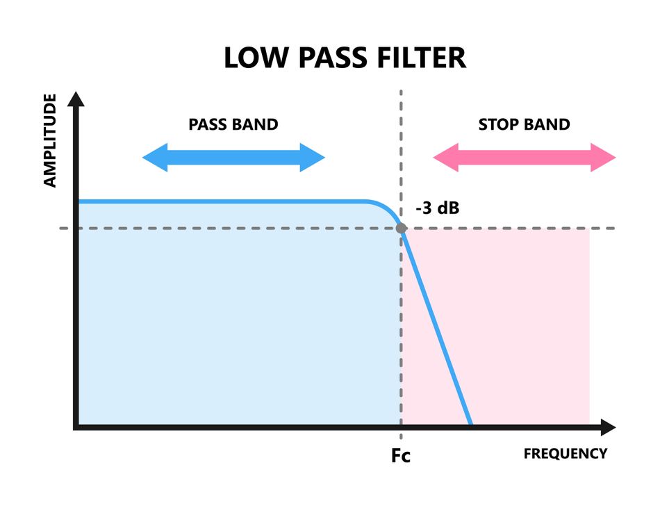
A Low-Pass Filter ideally passes all frequencies below some cutoff frequency fc with unity (or constant) gain, and completely attenuates frequencies above fc (the stop-band). Real low-pass filters have a gradual transition: frequencies much lower than fc pass with little attenuation (the passband), while frequencies much higher than fc are greatly attenuated (the stopband). The point at which the filter begins to significantly attenuate is the cutoff (often defined as the -3 dB gain point). Frequencies below fc are in the filter’s pass band, frequencies above are in the stop band.
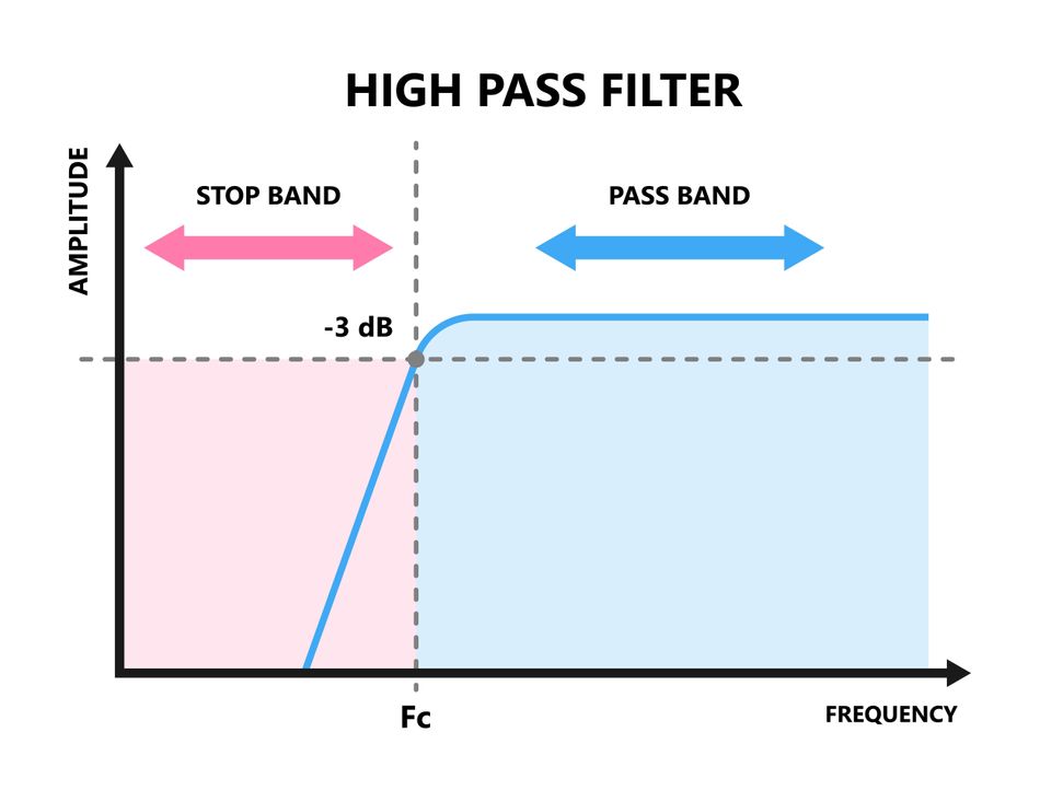
- A High-Pass Filter does the opposite: it passes frequencies above the cutoff fc, and attenuates those below fc. In an ideal high-pass filter, all low-frequency content (down to DC or 0 Hz) is blocked (stop-band), and only frequencies higher than the cutoff are allowed through (pass-band). In reality, again, there is a transition region around fc where the response changes from blocking to passing. Frequencies above fc constitute the pass band of a high-pass, and those below fc form the stop band.
Corner Frequency
The cutoff frequency fc, also called the corner or break frequency, is a critical parameter for both filter types. It is typically defined as the frequency, which the output signal power drops to half of the input power, which corresponds to the output voltage amplitude being 0.707 (70.7%) of the input (for a simple first-order filter). This point is also known as the -3 dB (decibels) point, because:

At fc, a first-order filter’s phase shift (discussed later) is 45 degrees (negative for low-pass, positive for high-pass).
The standard formula for the cutoff frequency of a simple RC filter (either low-pass or high-pass) is:

where R and C are the resistance and capacitance values in the circuit.
For an RL (resistor-inductor) filter, the formula is:

Understanding Low-Pass Filters
A low-pass filter allows low-frequency content to pass through relatively unchanged, while attenuating the amplitude of frequency components higher than the cutoff frequency. In other words, it’s selective to low frequencies.
Simple RC Low-Pass Circuit
The most basic implementation is a first-order passive RC low-pass filter. It consists of a resistor (R) in series with the input signal, and a capacitor (C) connected from the node between R and the output, down to ground. The output is taken across the capacitor. This configuration is shown below.

In this RC low-pass circuit, at low frequencies (far below fc), the capacitor’s reactance:

is very high (an uncharged capacitor looks like an open circuit at DC). Thus, most of the input voltage drops across the capacitor (which is also the output node) and very little across the resistor. This means the output Vout is almost equal to the input Vin at low frequency – the filter has near unity gain in the low-frequency range (the pass-band).
At high frequencies (far above fc), the capacitor’s reactance becomes very low. In this state, the capacitor shunts the signal to ground, and most of the input voltage drops across the resistor instead. The output across the capacitor becomes very small. Thus, for frequencies well above the cutoff, the output is heavily attenuated, and the filter effectively blocks the high-frequency content (stop-band).
At the cutoff frequency fc, the reactance of C equals the resistance R (Xc = R). This is the point where the output voltage is:

It’s not simply half the voltage because the division of voltage is between R and Xc as impedances (the 0.707 comes from the vector sum of equal resistor and capacitor impedance).
Frequency Response Characteristics
The Bode plot (frequency response curve) of a first-order low-pass filter is essentially flat (0 dB gain) at low frequencies, then transitions around fc into a downward slope at –20 dB/decade (–6 dB/octave). This means for every tenfold increase in frequency above the cutoff, the output amplitude (in dB) decreases by 20 dB. The phase of the output lags the input (since the capacitor takes time to charge). At very low frequencies, the phase shift is ~0° (input and output in phase).
At the cutoff, the phase shift is –45°. At very high frequencies, the output lags nearly –90° behind the input. In time domain terms, this lag means the filter output is “sluggish” in responding to rapid changes (the capacitor averages out fast fluctuations – integrating behavior).
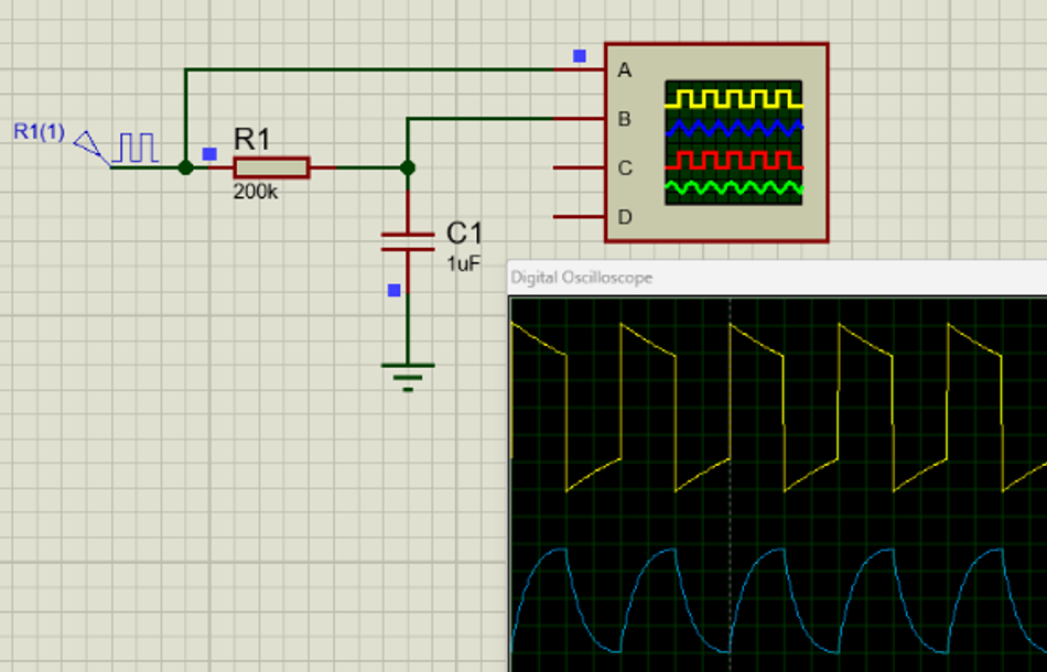
Low Pass RC Filter Example
To illustrate, if you feed a square wave (which has fast edges and high-frequency components) into a low-pass RC filter, the output will rise and fall more slowly than the input square edges – it looks like a charging and discharging exponential. If the square wave frequency is much lower than fc, you’ll still get a pretty square output (the capacitor has time to charge fully).
Suggested Reading: How to Discharge a Capacitor: A Comprehensive Guide for Engineers
Understanding High-Pass Filters
A high-pass filter passes high-frequency content and attenuates low-frequency components. In effect, it blocks slow or constant signals and allows rapid changes or high-frequency oscillations to come through. High-pass filters are widely used for tasks like AC coupling, eliminating 50/60 Hz mains hum or other low-frequency interference, and in audio to cut out rumbling noises or to send only the treble portion of audio to small speakers (tweeters).
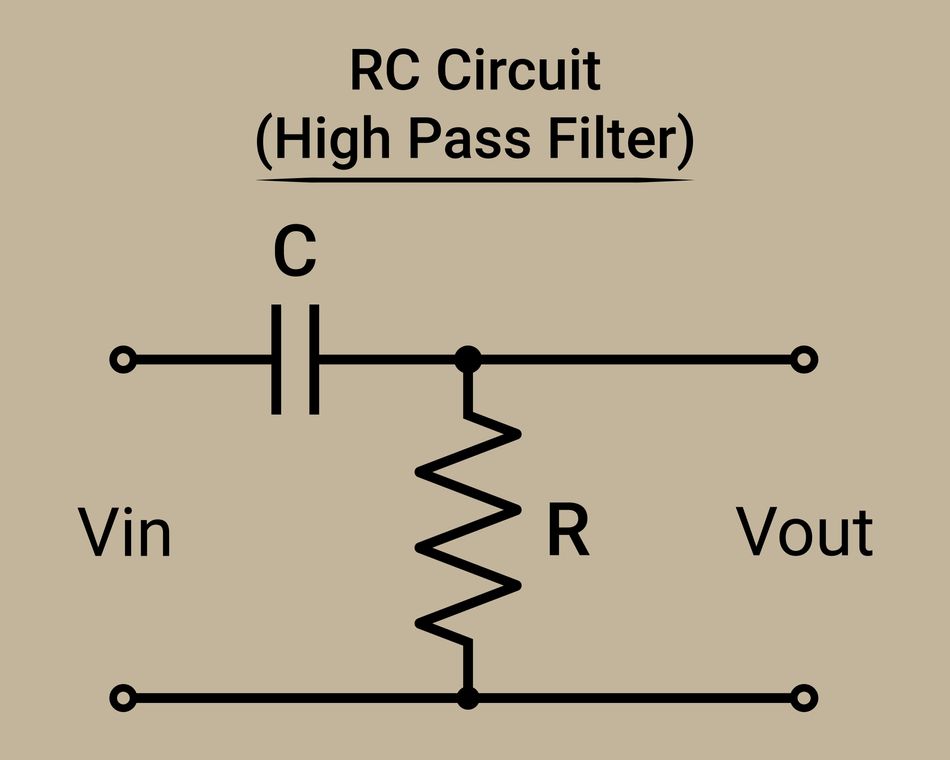
Simple RC High-Pass Circuit
A first-order passive high-pass filter can be made by simply swapping the positions of the resistor and capacitor in the low-pass circuit described earlier. That is, the capacitor C is in series with the input signal, and the resistor R is connected from the series node to ground. The output is taken across the resistor. This configuration is the exact inverse of the low-pass: now the capacitor comes before the resistor concerning the input, and the output is across the resistor.
In an RC high-pass circuit, consider the two extremes:
At DC or very low frequencies: The input is effectively constant or changing very slowly. A capacitor, when faced with DC, acts like an open circuit (it charges up but blocks steady current). Thus, at DC, the series capacitor will not pass the signal – it’s as if the input is disconnected from the resistor. No current flows, so no voltage is dropped across the resistor. The output is essentially zero. In the low-frequency limit, the high-pass filter’s output is fully attenuated (0 gain). Frequencies far below fclie in the stop band: the filter strongly rejects them, hence a high-pass is sometimes called a DC-block or bass-cut filter.
At high frequencies (well above fc), the capacitor’s reactance Xc becomes very small at high. In the limit of very high frequency, the capacitor behaves like a short circuit for AC signals. That means the input sees the resistor directly. The series combination of C and R at high f places almost the entire input across R. So the output across R ~ equals the input. Thus, in the high-frequency range, the high-pass filter passes signals with near-unity gain – this is the pass band (the output follows the input for fast-changing signals). Only at infinitely high frequency would any attenuation occur due to parasitics or non-ideal component behavior.
At the cutoff frequency fc, the capacitive reactance equals the resistor. The output is then 0.707 of the input (–3 dB). This is the border between the stop band and the pass band. Below fc, the output drops off rapidly, and above fc it flattens out.
Frequency Response Characteristics
The Bode magnitude plot for a first-order high-pass is essentially the mirror image of the low-pass plot. At low frequencies fc , the gain is very low. As frequency increases, the output starts rising. The slope in the stop band (low-freq side) is +20 dB/decade – meaning for each tenfold increase in frequency below cutoff, the output gain (in dB) goes up by 20 dB. Once the frequency passes fc, the gain approaches a flat line (0 dB asymptote) in the high-frequency pass band. In effect, the filter “turns on” at fc and then allows higher frequencies through. The transition is gentle for a first-order filter, stretching approximately a decade around fc (one decade below to one decade above is the transition band where output goes from –20 dB to 0 dB).

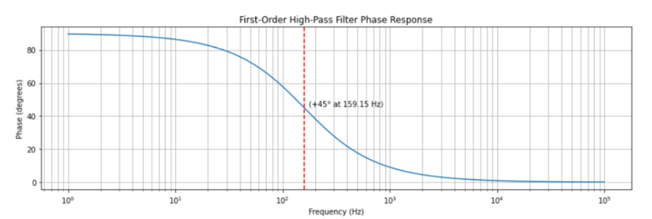
Phase Response of High Pass Filter
The phase response of the high-pass filter is positive (output leads input) for frequencies around the cutoff. At very high frequencies, the capacitor acts like a short, so the output is directly the input across R – meaning no phase difference (0° phase shift) in the high-frequency limit. At the cutoff fc, as mentioned, output leads by +45°. At very low frequencies, the output is almost 0 while input might be varying slowly; if we consider phase at these low frequencies, the output is almost 90° ahead of the input’s phase (in the sense that the tiny leakage through capacitor is derivative of input – e.g. if the input is a ramp, the output tends toward a constant which is a 90° phase lead in sinusoidal terms). Another way to see it: a high-pass filter differentiates a low-frequency input – the derivative of a sine is a cosine (90° phase lead). So as frequency → 0, phase → +90°.
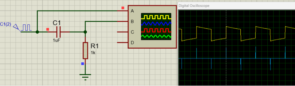
In the time domain, a high-pass filter tends to emphasize changes. For instance, if you input a step (a sudden DC jump), a high-pass output will produce a short spike (the capacitor passes the sudden change, then blocks the DC level). If you input a low-frequency sine wave that slowly oscillates, the high-pass might output a much smaller oscillation or nothing if it’s close to DC. But if you input a very high-frequency oscillation, the high-pass outputs nearly the same oscillation. This “spike at transitions” behavior is why an RC high-pass fed with a square wave outputs a sequence of rapid pulses – effectively acting as a crude differentiator circuit.
Low-Pass vs High-Pass: Side-by-Side Comparison
Low-pass and high-pass filters are two sides of the same coin. Here we compare their key characteristics and design aspects:
Feature | Low-Pass Filter (LPF) | High-Pass Filter (HPF) |
Frequency Range | Passes frequencies below the cutoff frequency (fc). | Passes frequencies above the cutoff frequency (fc). |
RC Configuration | Resistor is in series, and output is across the capacitor. | Capacitor is in series, and output is across the resistor. |
Impedance Behavior | Capacitor acts as a short circuit at high frequencies, diverting the signal. | Capacitor acts as an open circuit at low frequencies, blocking the signal. |
Pass-band Gain | The signal is not amplified; gain is 1 (or 0 dB) in the pass-band. | The signal is not amplified; gain is 1 (or 0 dB) in the pass-band. |
Stop-band Attenuation | Attenuates high frequencies at a rate of 20 dB per decade. | Attenuates low frequencies at a rate of 20 dB per decade. |
Phase Shift | Causes a lagging phase shift (output lags input). | Causes a leading phase shift (output leads input). |
Transient Response | Responds slowly to sudden changes, smoothing the signal. | Responds quickly to sudden changes, producing a spike. |
Applications | Removing high-frequency noise, smoothing signals, audio subwoofers, image blurring. | Removing DC offsets, audio tweeters, AC coupling, image sharpening. |
Practical Implementations and Design Considerations
Designing a low-pass or high-pass filter involves choosing a topology (passive or active, analog or digital) and selecting component values to achieve the desired cutoff frequency and filter order (slope steepness).
Passive Filters (RC, RL, RLC Networks)
The simplest way to implement a low-pass or high-pass is with passive components (resistors, capacitors, inductors). We’ve already covered the classic first-order RC filters: these are widely used due to their simplicity and are suitable for many applications where a gentle roll-off is acceptable.
Filters can be created using different component combinations, each with its own characteristics and applications.
RC Filters - RC (resistor-capacitor) filters are widely used because they are simple, inexpensive, and effective for moderate frequencies. A low-pass filter passes low frequencies while a high-pass filter passes high frequencies, with both sharing the same cutoff frequency (fc). The configuration of the resistor and capacitor determines the filter type. The specific values of these components affect the filter's interaction with the rest of the circuit. A moderate impedance is often chosen to avoid drawing too much current or being susceptible to noise.
RL Filters - RL (resistor-inductor) filters are more common in power and radio frequency (RF) applications. An inductor's behavior is the inverse of a capacitor: it passes low frequencies and blocks high frequencies. The filter's cutoff frequency is determined by the resistor and inductor values. RL filters are less common at lower frequencies due to the bulky size of inductors.
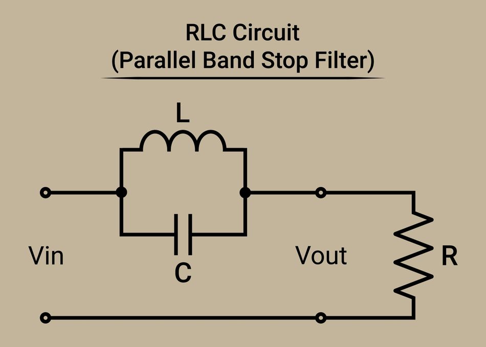
RLC filters - They combine all three components to create higher-order filters with sharper roll-offs. These can achieve steeper attenuation rates, which are often desirable for more precise filtering. While more complex to design due to impedance interactions, these filters offer a greater degree of control over the frequency response. Standard topologies like Butterworth and Chebyshev are used to achieve specific performance characteristics, but these often require carefully chosen component values.
Suggested Reading: PCB Components: A Comprehensive Technical Guide to Passive, Active, and Electromechanical Parts
Active Filters
Active filters incorporate amplifying devices (such as operational amplifiers) in addition to R, C (and sometimes L) components. By using op amps, we can overcome some limitations of passive designs:
We can get gain in the pass-band if desired.
We can buffer stages to avoid loading interactions, which makes designing higher-order filters easier.
We can implement filter configurations that simulate inductors or more complex poles without using physical inductors (e.g., the Sallen-Key filter, multiple feedback topology, state-variable filters, etc.).
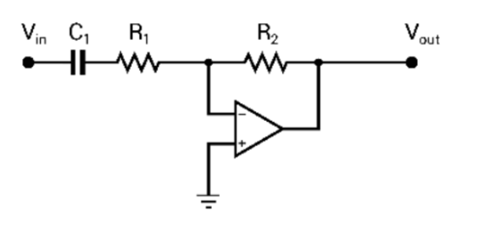
Filters can be designed using active components, primarily op-amps, which offer significant advantages over passive filters. An active filter uses an op-amp to buffer the output, preventing the filter from being affected by the next circuit stage. This buffering also allows for the inclusion of gain, which can be used to amplify the signal or compensate for signal loss.
The Sallen-Key topology is a popular active design for creating second-order low-pass or high-pass filters with a steeper roll-off of -40 dB per decade. This design allows for precise control over the filter's characteristics, such as achieving a flat frequency response (Butterworth) or a steeper cutoff with some ripple (Chebyshev).
A key advantage of active filters is the ability to easily combine them. For instance, you can cascade multiple second-order filters, each with its op-amp, to create a much higher-order filter. This achieves a sharper roll-off while still maintaining a stable signal and even compensating for losses by adding gain. Active filters are versatile and can be designed for various applications, such as removing unwanted frequencies in audio systems or preventing baseline drift in sensor signals.
Further Reading: Difference between Active and Passive Filters?
Digital Filters (DSP Implementations)
In modern digital systems, filtering is often performed digitally after sampling a signal (assuming you have sufficient sampling rate and an ADC). Digital filters can achieve low-pass or high-pass behavior through algorithms rather than physical components. While this drifts from our analog focus, it’s worth noting:
A digital low-pass filter could be as simple as taking a moving average of samples (which smooths out rapid changes, acting as a low-pass). More sophisticated designs use FIR or IIR filter structures with coefficients tuned to give a desired frequency response (e.g., a digital Butterworth low-pass).
A digital high-pass filter can be implemented by transforming a low-pass design. One common trick: take the input signal and subtract a low-pass filtered version of itself – this yields a high-pass (since you’re removing the low-frequency content, leaving the high-frequency part).
The advantages of digital filters are that they can achieve very sharp frequency cutoffs (like 100 dB attenuation in stop-band, multi-kHz orders) without the instability or component tolerance issues of analog filters. They can also adapt on the fly, etc. The trade-off is you need to have digitized the signal (so often an analog anti-aliasing low-pass is still required before the ADC to avoid aliasing unwanted high frequencies into the digital band). Digital high-pass filters are commonly used in data post-processing – for example, removing baseline wander in digital ECG data or high-pass filtering accelerometer data to focus on vibrations rather than gravity.
For digital design engineers, it’s useful to remember that the fundamental concepts remain the same: the low-pass lets you smooth data or focus on slow trends, the high-pass lets you remove drifts and focus on rapid changes. The difference is just implementing via code (filter coefficients) instead of resistors and capacitors. Tools like MATLAB, Python SciPy, or DSP libraries can design digital low-pass and high-pass filters given specifications (e.g., cutoff frequency, filter order).
Tuning and Practical Tips
Selecting Cutoff: Determine what frequency range is important for your signal. If you want to smooth out noise above 100 Hz, you might set a low-pass around 100 Hz. If you want to block any drift below 0.1 Hz, set a high-pass around 0.1 Hz. Keep in mind the transition band: a first-order filter will start attenuating one decade before and only fully attenuate one decade after (roughly). Higher-order filters can transition faster.
Filter Order: If a first-order (-20 dB/decade) is not sufficient (maybe you need stronger suppression of unwanted frequencies near the cutoff), consider second-order (-40 dB/decade) or higher. Every order adds complexity (and for analog, potentially more op amps or inductors). Active filters make higher orders easier to manage.
Component Tolerances: Real resistors and capacitors have tolerances (5%, 1%, etc.). For a simple RC, 5% might be fine. But for a higher-order filter, small variations can detune the cutoff or cause slight peaking. For critical filters, use precision components or trim them in the circuit.
Loading Effects: Remember that the output of a passive filter has an output impedance. If you connect a low impedance load, it can alter the filter response. A rule of thumb: make the load impedance at least 10 times the output impedance of the filter to minimize loading error. Buffering with an op amp is a solution if needed.
Op Amp Bandwidth: For active filters, ensure the op amp’s gain-bandwidth product is high enough. If you are making a 100 kHz low-pass filter with a gain of 1, the op amp should have a GBW >> 100 kHz to maintain the designed response.
Simulation and Testing: It’s good practice to simulate filter designs (using SPICE for analog or Python/MATLAB for digital) to see the frequency response and step response. This can catch issues like unexpected resonances or verify the cutoff is correct.
Conclusion
Low-pass and high-pass filters are essential for controlling a signal's frequency content. A low-pass filter allows low frequencies through while blocking high frequencies, effectively smoothing the signal. Conversely, a high-pass filter blocks low frequencies and passes high frequencies, emphasizing rapid changes. Both are defined by a cutoff frequency (fc) where the signal is attenuated by half power.
Filters can be simple and passive (using only resistors and capacitors) or more complex and active (using op-amps for greater control and gain). The choice of filter depends on the application: use a low-pass to remove high-frequency noise and a high-pass to eliminate low-frequency drift or DC bias. They are different tools, not a matter of one being "better."
FAQs
1. Why don’t passive filters have gain?
Passive filters lack amplifying components, so the output signal can never be stronger than the input signal.
2. What is the difference between filter order and roll-off?
Filter order refers to the number of reactive components (e.g., capacitors or inductors) and determines the steepness of the roll-off, which is the rate at which the filter attenuates frequencies in the stop-band.
3. What does "pole" mean in filtering?
A pole is a mathematical term representing a reactive component's effect on the filter's behavior. A single reactive element creates a first-order filter with one pole and a roll-off of 20 dB per decade.
4. What is a Butterworth filter?
A Butterworth filter is a type of active or passive filter designed to have the flattest possible frequency response in its pass-band, without any ripples.
5. What is the purpose of an anti-aliasing filter?
An anti-aliasing filter is a low-pass filter used before an analog-to-digital converter (ADC) to remove high frequencies that could cause errors, or "aliasing," when the signal is sampled.
6. How is a filter's cutoff frequency determined?
A filter’s cutoff frequency (fc) is the point where the output power drops to 50% of the input power, corresponding to a -3 dB reduction in signal amplitude.
7. Why do some circuits use both an LPF and an HPF?
Combining an LPF and an HPF creates a band-pass filter, which allows a specific range of frequencies to pass while blocking everything below and above that range.
References
https://cdautomation.co.uk/complete-guide-high-and-low-pass-filters/
https://www.rfpage.com/low-pass-high-pass-and-band-pass-filters-simple-explanation/
https://www.digikey.com/en/maker/blogs/2024/the-basics-of-low-and-high-pass-filters
RL and RC Low Pass Filter Circuit and Formula | Wira Electrical
Passive Low Pass Filter - Passive RC Filter Tutorialhttps://qmicrowave.com/blog/high-pass-vs-lowpass-filters-which-is-best-for-your-application