Accurate Measurements using Shunt Resistors and Current Sense Modules in High-Energy Storage Applications
Article 4 of the Power Conversion Series. Shunt resistors combined with a current-sense module can deliver highly accurate battery management systems in high-energy applications.
08 Apr, 2021. 6 minutes read

Image: Nissan
This is the fourth article in a 5-part series exploring power conversion. The series will provide insight into how the rapid electrification of vehicles and the switch to renewable energy is driving the demand for safe and reliable power conversion and electronic components.
The articles were originally published in an e-magazine, and have been substantially edited by Wevolver to update them and make them available on the Wevolver platform. This series is sponsored by Mouser Electronics, an online distributor of electronic components. Through their sponsorship, Mouser Electronics supports engineers in designing sustainable and efficient applications for a greener future.
Introduction
The need to monitor the state of health of lithium-ion cells in battery packs during charging and discharging is a key requirement for Battery Management Systems (BMS) in high-energy applications such as hybrid electric vehicles (HEVs) and battery electric vehicles (BEVs). Maintaining performance and safe operation is of paramount importance, as lithium-ion chemistries are prone to degradation and aging issues. A dangerous thermal runaway condition can occur if the ambient temperatures are out of specification or if the batteries are undercharged or overcharged, possibly causing cracks in the carbon and lithium plating.
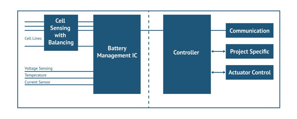
The three parameters measured by the BMS (Figure 1) to determine the state of a cell’s health are cell voltage, temperature, and current. The traditional solution employed to measure these parameters has been the use of shunt resistors. These passive components feature a relatively high absolute tolerance of 5 percent. However, the overall accuracy, when combined with a current sense module, can be reduced to as low as 0.01 percent.
This article provides helpful BMS design information on the accuracy level that can be obtained using Bourns® Model CSM2F Series shunt resistors combined with a current-sense module designed for this purpose.
Bourns® Shunt Resistors for Battery Current Measurement
Bourns offers three shunt resistor models qualified by Bourns for harsh environment energy storage applications. The resistive element in all three models consists of large copper terminals as can be seen in the examples of the CSM Series on the left. Given that the resistivity of copper is 1.72 x 10⁻⁸ Ωm and that the resistance will increase by 0.393 % for every extra degree Celsius in temperature, the overall coefficient of resistance between the two points will be higher than the resistivity of the resistor alloy (max. 50 ppm/˚C or 0.05 %/˚C). If the distance between the two measurement points in copper is 3 mm in total as is the case with CSM2F-8515, the temperature coefficient of resistance, or TCR, will increase from 50 ppm/˚C (TCR of element) to 150 ppm/˚C (TCR of combined element plus copper terminal). The maximum current these shunts can carry is quite high. The Bourns® Model CSM2F-7036, for example, using Ohm's Law can carry 1000 A, DC/DC at a maximum power 50 watts. A typical battery pack for an HEV is 24 kWH. This is equivalent to 500 ampere hours in a 48 V vehicle. Therefore, the current can be very high, especially during periods of high power such as acceleration when moving or fast charging when stopped.
Recommendations for Signal Processing
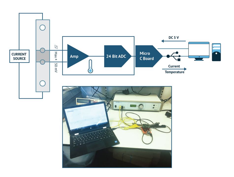
Bourns developed the typical current source module block diagram (Figure 2) to evaluate a shunt-based current measurement system’s accuracy. The module consists of an Analog Front End (AFE) with a current sense amplifier with analog buffer, 24-bit ADC and Serial Peripheral Interface (SPI). Several high-voltage bidirectional current-sense amplifiers from ADI, such as the model AD8210 or AD8211, have gains of 20 and common-mode voltages of up to 65V.
To evaluate the shunt, Bourns tested its Model CSM2F-8518 (100μohm nominal resistance), as shown in Figure 2. A single-board microcontroller kit is programmed to communicate with the module over an SPI connection. The current for the measurement was generated using a precision current source.
The first measurement to be determined is the resistance of the shunt. This is done using the known current from the current source and a precision 4-wire voltmeter. Once the actual resistance of the shunt is measured, then the voltage across the shunt using the current sense module can be compared with the actual resistance value.
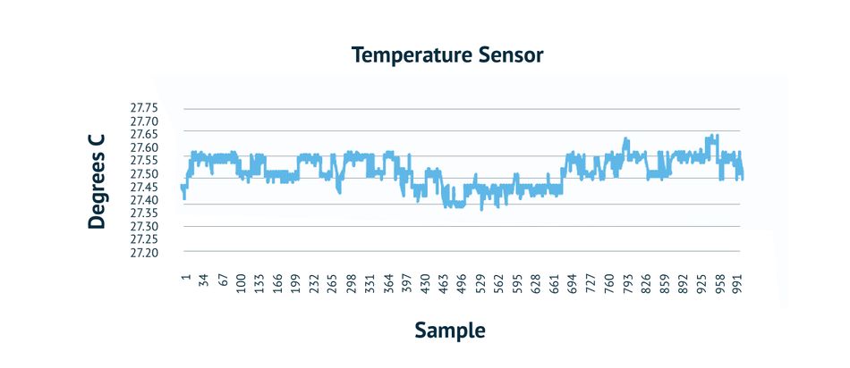
The current sense amplifier has a common mode voltage of 80V maximum, allowing for the module to be placed at the high end in 48V battery systems. The module also contains a surface-mount temperature sensor with a PWM output proportional to the ambient temperature. Figure 3 shows the temperature sensor output at room temperature. The amplifier power is supplied by a DC supply of +5V. This experiment’s power comes from a Low Drop Out (LDO) regulator with the original supply coming from the USB interface. For an isolated 5V supply, a low-power micro converter using the ADI LTC8301 (flyback or push-pull) can provide the necessary isolation with the required safety level.
Figure 4 shows the data points collected from the A/D input terminals with an average of 22.44364mV and peak-to-peak variation of 0.007mV over the sampling period.
Determining Measurement Accuracy
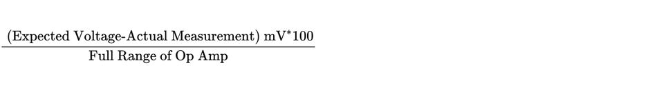
The accuracy of the measurements at room temperature can be calculated using the following formula.
The accuracy:
Helping Ensure BMS Safety and Long Life
Currents of several hundred amperes are measured by BMS in various e-mobility applications during battery charging and discharging. The ability to measure current accurately provides critical information for safety and ensures long battery pack life. Using an ultra-low resistance shunt resistor, and a precision AFE, can provide very accurate readings from very high to very low current levels with accuracy tolerances of less than 0.01 percent. Also, temperature sensing, and look-up tables from Bourns, can improve measurement accuracy as the temperature increases.
This article has provided a proven methodology to measure the cell voltage, temperature, and current to determine the state of health of a battery cell. Key in this process are Bourns® current-sense amplifiers featuring low offsets and high common mode voltages that enable high accuracy with the shunt being placed at the high end in 48V applications.
Bourns® Model CSM2F Series shunt resistors are manufactured in an International Automotive Task Force-approved facility certified to build components for harsh environment applications such as in high-energy BMS used in HEVs and BEVs.
This article was originally written by Mouser and Bourns in an e-magazine and substantially edited by the Wevolver team. It's the fourth article of a 5-part series exploring power conversion. Future articles will dive into power conversion solutions for critical applications such as automotive and renewable energy.
Article 1 explored how designers can make design decisions when working with high-voltage energy storage systems.
Article 2 discussed the potential of rechargeable batteries.
Article 3 examined the method for selecting transformers for Battery Management Systems (BMS).
Article 4 explained the necessity of shunt resistors to deliver accurate Battery Management Systems.
Article 5 provided an overview of innovative transformer solutions for power conversion.
About the sponsor: Mouser
Mouser Electronics is a worldwide leading authorized distributor of semiconductors and electronic components for over 1,100 manufacturer brands. They specialize in the rapid introduction of new products and technologies for design engineers and buyers. Their extensive product offering includes semiconductors, interconnects, passives, and electromechanical components.