UART Protocol: Understanding Serial Communication for Engineers
A deep dive into the UART protocol for digital design engineers, hardware engineers, and electronics engineering students. Learn how this common serial interface works, its configuration parameters, applications, and how it differs from other protocols.

28 Jan, 2026. 18 minutes read

Key Takeaways
UART Overview: UART is a simple, two‑wire asynchronous communication protocol that converts parallel data to serial form and vice versa. It uses start and stop bits to frame the data, making communication independent of a shared clock [1].
Data Framing: Data frames typically follow an 8-bit, no‑parity, one‑stop‑bit (8N1) format, achieving about 80 % protocol efficiency. Oversampling and proper baud‑rate matching are critical for reliable communication.
Modern Features: Modern UARTs often include FIFO buffers, interrupt support, and DMA, allowing microcontrollers to offload data transfer and achieve higher throughput.
Hardware Interfaces: Hardware interfaces such as TTL serial, RS‑232, and RS‑485 extend the UART over different voltage levels and distances. RS‑232 uses single-ended, inverted voltages, supporting up to ~15 m at 115 kbps, while RS‑485 uses differential signaling to support multi-drop networks up to 1.2 km.
Market and Trends: The UART market continues to grow due to IoT, automotive, and industrial automation applications. Forecasts estimate around US$600 million in 2025, reaching about US$975 million by 2032. Emerging trends include AI-optimized low-power designs, multi-channel UART chips, and integration with 5G and edge-computing systems.
Introduction
Serial communication is the backbone of countless electronic systems. When microcontrollers talk to sensors, motors, or debugging consoles, they often rely on the Universal Asynchronous Receiver‑Transmitter, or UART protocol. A UART converts parallel data from a CPU into a time‑encoded serial stream and back again.
Understanding UART protocol is essential for engineers and students working with digital designs, as it forms the foundation for connecting sensors, modules, and microcontrollers in a wide range of applications. This guide explores the UART protocol, its architecture, configuration options, implementation techniques, and emerging trends, providing a complete overview for anyone seeking to master serial communication in hardware systems.
Fundamentals of UART Communication
What is a UART?
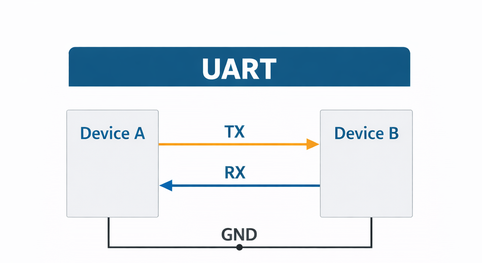
UART is a hardware communication peripheral that enables the transmission and reception of data between two digital devices by converting data between parallel and serial formats [1]. UART operates using asynchronous serial communication, meaning that data is transmitted without a shared clock signal between the sender and receiver.
Internally, digital systems such as microcontrollers and processors operate on parallel data buses, while external communication is often more efficient and practical using serial data streams. UART bridges this gap by handling the serialization of outgoing data and the deserialization of incoming data in a standardized and reliable manner.
UARTs typically support three operating modes: simplex (one-way communication), half-duplex (two-way communication, but not simultaneously), and full-duplex (simultaneous bidirectional communication using separate transmit and receive lines).
Principle of Operation
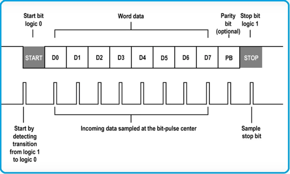
The primary function of a UART is to convert parallel data from a processor into a serial bit stream for transmission and to reverse the process on reception. A transmitter shift register takes a byte of data, appends a start bit, the data bits (least significant bit first), an optional parity bit, and one or more stop bits, then outputs the bits at a defined baud rate. On the receiving side, an oversampled clock monitors the incoming line for a transition from the idle level (logic “1” on TTL) to the start bit (logic “0”). Once detected, the receiver samples each bit at the middle of its period, reconstructs the byte, and verifies the stop bit and parity.
Key characteristics include:
Feature | Description |
Asynchronous communication | No shared clock; timing derived from start and stop bits. Requires accurate baud‑rate matching between transmitter and receiver (typically within ±2–10 %). |
Data frame | Start bit (always logic 0), 5–9 data bits (LSB first), optional parity bit, and one or more stop bits (logic 1). |
Efficiency | Standard 8N1 format (8 data bits, no parity, 1 stop bit) yields 80 % efficiency because two framing bits accompany each data byte. |
Flow control | Optional hardware (RTS/CTS) or software (XON/XOFF) signals manage buffer overflow and ensure that the receiver can handle incoming data. |
Error detection | A parity bit can detect single‑bit errors. Receivers also detect framing errors (missing stop bit), overrun errors (data overwritten before reading), and break conditions (long low level). |
UART Architecture and Internal Blocks
The UART architecture is designed to handle serial communication efficiently by dividing functionality into well-defined internal blocks. Each block plays a specific role in transmitting, receiving, timing, buffering, and monitoring data. Understanding these internal components is essential for engineers who configure UART peripherals at the register level or design systems that rely on reliable serial communication.
Transmitter Block
The transmitter block is responsible for sending data from the host system to an external device. Parallel data written by the processor into the transmit data register is first buffered and then passed to the transmitter logic. This block appends the start bit, optional parity bit, and stop bit(s) to the data, forming a complete UART frame. The framed data is then shifted out bit by bit onto the transmit (TX) line at a rate defined by the baud rate generator. Status flags associated with the transmitter indicate conditions such as transmit buffer empty or transmission complete, allowing software to manage data flow efficiently.
Receiver Block
The receiver block performs the inverse operation of the transmitter. It continuously monitors the receive (RX) line for a falling edge that indicates a start bit. Once detected, the receiver samples the incoming data bits at precise intervals determined by the baud rate generator. The serial data stream is then reconstructed into parallel form and stored in a receive buffer. The receiver block also evaluates the validity of the received frame, checking for correct stop bits and parity, and reports any detected errors to the control logic.
Baud Rate Generator
The baud rate generator is a critical timing component within the UART. It derives the required bit timing from the system clock and ensures that both transmission and reception occur at the configured baud rate. Typically implemented as a programmable divider, the baud rate generator allows software to select standard baud rates such as 9,600, 57,600, or 115,200 bits per second. Accurate baud rate generation is essential, as excessive clock mismatch between the transmitting and receiving devices can lead to sampling errors and data corruption.
Shift Registers
Shift registers are central to UART operation, as they handle the conversion between parallel and serial data formats. On the transmit side, a parallel-to-serial shift register loads the framed data and shifts it out one bit at a time. On the receive side, a serial-to-parallel shift register collects incoming bits and assembles them into a complete data word. These registers operate synchronously with the baud rate generator, ensuring correct bit timing and alignment throughout the communication process.
Control and Status Registers
Control and status registers provide the software interface to the UART hardware. Control registers allow configuration of key parameters such as baud rate, data length, parity mode, stop bits, and flow control options. Status registers report real-time information about the UART’s operating state, including transmit and receive readiness, buffer status, and error conditions. Together, these registers enable flexible configuration and precise control of UART behavior in embedded systems.
FIFO Buffers
Many modern UART implementations include First-In, First-Out (FIFO) buffers on both the transmit and receive paths. FIFO buffers temporarily store multiple data bytes, reducing the frequency of processor intervention and minimizing the risk of data loss during high-speed communication. By allowing burst transfers of data, FIFOs improve overall throughput and are especially beneficial when UART is used alongside interrupts or direct memory access (DMA).
Error Detection Logic
UART includes basic error detection mechanisms to identify common communication issues. Error detection logic monitors conditions such as framing errors (missing or invalid stop bits), parity errors, and overrun errors when received data is not read in time. While UART does not provide advanced error correction, these indicators allow software to detect faults and take appropriate corrective action, such as retransmission or error logging.
UART Data Framing and Timing
Frame-Based Communication
UART communication is based on a defined data framing structure that enables reliable transmission without a shared clock. Data is sent in discrete frames, with each frame representing a single data word, typically a character or byte. Frame boundaries allow the receiver to synchronize timing independently for each transmission.
Start Bit
Each UART frame begins with a start bit, which is always logic low. The start bit indicates the beginning of a new data frame and provides the receiver with a timing reference. Detection of the start bit triggers the receiver’s internal timing logic [2].
Data Bits
Following the start bit are the data bits, which contain the actual information being transmitted. UART supports configurable data lengths, usually ranging from 5 to 9 bits. The most commonly used configuration in modern systems is 8 data bits, as it aligns well with standard byte-oriented processing [2].
UART communication often transmits data encoded in ASCII format, especially for human-readable text such as terminal commands and debug messages. Each ASCII character is typically sent as an 8-bit data frame, making the UART well-suited for console interfaces and serial monitors.
Parity Bit
An optional parity bit may follow the data bits to provide basic error detection. Parity can be configured as an even or odd number, or disabled. When enabled, the parity bit allows the receiver to detect single-bit transmission errors, though it does not provide error correction.
Stop Bit(s)
The frame ends with one or more stop bits, which are transmitted as logic high. Stop bits signal the end of a data frame and ensure a minimum idle period before the next transmission. They also help the receiver recover timing alignment between consecutive frames.
Common Frame Formats
UART frame formats are commonly described using shorthand notation. The most widely used format is 8N1, which represents eight data bits, no parity, and one stop bit. Other formats, such as 7E1 and 8O2, are used in specific applications requiring additional error detection or timing margin.
Bit Timing and Sampling
UART relies on precise bit timing derived from the configured baud rate. After detecting the start bit, the receiver samples each data bit at its midpoint to minimize the effect of noise and signal transitions. Accurate timing is essential for correct data reconstruction.
Oversampling Techniques
Most UART implementations use oversampling, typically at 8× or 16× the baud rate [3]. Multiple samples are taken for each bit, and the final bit value is determined using averaging or majority voting. Oversampling improves tolerance to clock mismatches, jitter, and noise.
Protocol Efficiency
UART framing introduces overhead due to start, parity, and stop bits. In an 8N1 configuration, 10 bits are transmitted for every 8 bits of data, resulting in approximately 80 % protocol efficiency. Designers must balance efficiency and reliability when selecting frame parameters.
Configuration Parameters and Design Considerations
Configuring a UART correctly is essential for reliable and efficient serial communication. Although the fundamentals of UART data framing and timing define how bits are transmitted and received, design parameters determine how the UART peripheral behaves in a practical system. Engineers must consider baud rate, frame format, flow control, and power consumption to optimize performance and maintain data integrity.
Baud Rate Selection and Tolerance
The baud rate specifies the number of bits transmitted per second and directly impacts bit timing and synchronization. Standard baud rates include 9,600, 19,200, 57,600, and 115,200 bps, but many microcontrollers support custom rates through programmable dividers. Accurate selection of the UART baud rate is critical: if the transmitter and receiver differ significantly, sampling errors can occur, leading to framing or parity errors. In practice, UART systems tolerate small mismatches, typically within 2–3%, depending on the frame format and oversampling technique. High-speed communication or long cable runs often require tighter tolerances and more precise clock sources.
Clock Accuracy and Mismatch
Because UART is asynchronous, both devices rely on independent clocks. Any deviation between the transmitter and receiver clocks accumulates over the duration of a frame. Mismatch beyond the acceptable limit can result in misinterpreted data bits. Engineers must account for clock drift, oscillator tolerance, and temperature variations when selecting components or designing communication links, particularly in industrial or high-reliability systems.
Data Length, Parity, and Stop Bits
The frame format—including data length, parity, and stop bits—affects both efficiency and error detection. Common configurations are 8N1 (eight data bits, no parity, one stop bit) and 7E1 (seven data bits, even parity, one stop bit). Increasing data bits per frame improves throughput, while adding parity or extra stop bits increases reliability at the cost of efficiency. Designers must balance throughput, error detection needs, and hardware compatibility when choosing frame parameters.
Flow Control
Flow control mechanisms prevent buffer overruns when data is transmitted faster than it can be processed. None (simple UART) relies on software to manage timing, suitable for short, predictable data bursts. Hardware flow control uses additional lines, such as RTS (Request to Send) and CTS (Clear to Send), to signal when the receiver is ready. Software flow control uses special characters (XON/XOFF) to start and stop data transfer. Selection depends on the application, data rate, and system complexity.
Power Consumption Considerations
UART peripherals contribute to overall system power consumption, particularly in battery-powered devices. Factors influencing power include clock frequency, transmit speed, and idle modes. Many modern UARTs support low-power or sleep modes where the peripheral can pause operation until activity is detected. Efficient configuration of frame rates, buffer sizes, and interrupts can reduce processor wakeups and conserve energy, especially in IoT and embedded applications.
Parameter | Options & typical values | Purpose |
Baud rate | 300 bps to several megabits; common values include 9 600, 19 200, 38 400, 57 600, 115 200, 230 400 and 1.5 Mbps. | Defines the duration of each bit; both ends must match within ±2–10 %. |
Data bits | Typically 7 or 8 bits; some devices support 5, 6, 9, or more bits for special protocols. | Specifies the number of bits in each data word. |
Parity | None, even, odd, mark (always 1) or space (always 0). Parity adds a simple checksum to detect single‑bit errors. | Error detection; optional to reduce overhead. |
Stop bits | 1, 1.5, or 2 stop bits. More stop bits give the receiver additional time to process data, but reduce throughput. | Indicate the end of frame and allow resynchronisation. |
Flow control | Software: XON/XOFF uses in‑band control characters to start/stop transmission; suitable for low‑speed links. Hardware: RTS/CTS lines signal when the receiver’s buffer is ready. | Prevent buffer overflow by pausing transmission when the receiver cannot keep up. |
Voltage levels | Logic‑level (TTL/CMOS), RS‑232 (±3 V to ±15 V, inverted), RS‑485 (±1.5 V differential) | Determine the electrical interface and communication distance |
UART Implementation in Embedded Systems
UART is one of the most commonly used communication peripherals in microcontrollers (MCUs) and system-on-chip (SoC) designs. Its simplicity, low pin count, and reliable operation make it ideal for connecting sensors, modules, and other devices in embedded systems. However, implementing UART efficiently requires understanding both hardware features and software strategies, including register configuration, interrupt handling, DMA support, and higher-level software abstractions.
UART in Microcontrollers and SoCs
Most modern MCUs integrate one or more UART peripherals directly on-chip, providing full-duplex serial communication without the need for external components. These peripherals include transmitter and receiver logic, buffers, baud rate generators, and control/status registers. UART is also available in SoCs, often alongside other communication interfaces like SPI and I²C, allowing designers to choose the most suitable protocol for their application. The integration reduces board complexity, conserves I/O pins, and ensures tight timing control for high-speed data transfer.
In popular development platforms such as Arduino, UART is exposed through dedicated hardware serial pins (TX and RX), as documented in the Arduino microcontroller datasheets.
Register-Level Configuration
At the hardware level, UART peripherals are configured through memory-mapped registers. Control registers allow selection of baud rate, data length, parity, stop bits, and flow control options. Status registers provide real-time information about transmit and receive buffers, errors, and operational state. Engineers must understand these registers to configure the UART correctly and monitor its operation. For example, setting the transmit enable bit activates the transmitter logic, while reading the receive data register retrieves incoming data. Misconfigurations can lead to framing errors, data loss, or communication failure.
Interrupt-Driven vs Polling-Based Communication
UART data can be managed using either polling or interrupt-driven mechanisms. In polling, the processor continuously checks status registers to determine if the transmit buffer is empty or if new data has arrived. While simple, polling can waste CPU cycles, particularly at high data rates. Interrupt-driven UART, on the other hand, triggers the processor only when certain events occur, such as buffer availability or error detection. This approach allows the CPU to perform other tasks between UART events, improving overall system efficiency. Many embedded systems use an interrupt-driven UART for real-time applications where responsiveness is critical.
DMA-Based UART Communication
For high-speed or large-volume data transfers, UART can leverage Direct Memory Access (DMA). DMA allows the peripheral to move data directly between memory and UART buffers without CPU intervention, reducing processor load and enabling continuous data streaming. In applications like sensor logging, audio communication, or industrial control, DMA-driven UART minimizes latency and prevents data loss during bursts of high-throughput traffic. Proper configuration of DMA channels, transfer sizes, and interrupt priorities is essential to achieve optimal performance.
Software Drivers and Hardware Abstraction Layers (HAL)
Beyond hardware, UART operation is often managed through software drivers and hardware abstraction layers provided by MCU vendors. HAL libraries simplify register-level configuration and provide standard APIs for initialization, transmission, and reception. They often include support for interrupt and DMA operations, error handling, and flow control. Using HAL or driver libraries improves code portability across devices, reduces development time, and minimizes low-level errors. In larger systems, UART drivers may be integrated into real-time operating systems (RTOS) to handle concurrent tasks and scheduling, ensuring reliable and deterministic communication.
Hardware Interfaces: TTL, RS‑232, and RS‑485
TTL and CMOS serial
The simplest UART interface operates at logic levels compatible with microcontrollers—typically 3.3 V or 5 V. This TTL/CMOS serial is suitable for short distances (centimetres to a few metres) on a printed circuit board or within an enclosure. Because the voltage range for logic “1” differs between 3.3 V and 5 V devices, a level‑shifting circuit or open‑collector driver is often required. Without proper interfacing, connecting a 5 V transmitter to a 3.3 V receiver can damage the lower‑voltage device [4].
RS‑232
RS‑232 extends UART over longer cables by using higher voltage levels and inverted logic: a logical “1” is represented by a voltage between −3 V and −15 V, and a logical “0” by +3 V to +15 V. Level‑shifting ICs such as the MAX232 convert between logic‑level UART and RS‑232. RS‑232 links typically support distances up to 15 m at speeds up to 115 200 bps; some implementations achieve a few megabits over shorter cables. The standard defines DB‑9 or DB‑25 connectors with additional modem control lines (RTS, CTS, DTR, DSR, CD, RI) for hardware flow control and handshake.
RS‑485
For industrial environments and long‑distance networks, RS‑485 employs differential signaling over twisted pairs. Drivers send complementary voltages on two wires, enabling common‑mode noise rejection and reliable communication up to 1.2 km at 10 Mbps. RS‑485 supports multi‑drop (up to 32 devices on a bus) by controlling when each node drives the line; half‑duplex systems share a single pair, while full‑duplex systems use two pairs. Termination resistors and bias resistors ensure a defined idle state. Because RS‑485 only defines the physical layer, UART frames still govern the data format.
Comparison Table
Interface | Signaling | Typical voltage | Distance | Data rate | Multi‑drop support |
TTL/CMOS | Single‑ended | 3.3 V / 5 V | < 5 m | Up to a few Mbps | No |
RS‑232 | Single‑ended, inverted | ±3 V to ±15 V | ≤ 15 m | Up to ~115 k bps (higher for short cables) | No |
RS‑485 | Differential | ±1.5 V differential | ≤ 1.2 km | Up to 10 Mbps | Yes (32 devices) |
Error Detection and Handling
Parity and Framing Errors
Adding a parity bit provides single‑bit error detection by enforcing that the total number of logic “1” bits in the data plus the parity bit is either even or odd. When parity is disabled (common for efficiency), error detection must rely on higher‑layer protocols or checksums. Framing errors occur when the receiver samples a stop bit as logic “0,” indicating a mismatch in baud rate or noise on the line. Overrun errors happen when the receive buffer is full and new data arrives; proper flow control or larger FIFOs mitigate this. A break condition occurs when the line remains low for longer than a character frame—often used as an attention signal.
Oversampling and Tolerance
To improve resilience to clock differences and noise, UART receivers oversample the incoming signal—commonly at 16× the baud rate. Sampling at multiple points allows digital logic to determine the best timing to latch each bit and to filter out jitter or short disturbances. Some modern UARTs offer higher oversampling factors (32× or 64×), fractional baud‑rate generators, and automatic baud detection.
The allowable difference between the transmitter and receiver clocks depends on the number of data bits and the oversampling strategy. With eight data bits, the sampling window must remain inside the valid bit period until the last bit is captured. AllAboutCircuits estimates that the total difference should be less than approximately 3.75 % to avoid sampling the stop bit too early. In practice, ±1 % or better accuracy is desirable for long frames or 9‑bit modes.
Advanced Error Checking
For applications requiring robust communication, engineers often implement higher‑layer protocols on top of UART. Frames may include headers, lengths, and checksums or cyclic redundancy checks (CRC). For example, custom protocols in industrial automation use 9‑bit mode (address/data) or encapsulate messages with a header and 16‑bit CRC. Implementing timeouts and acknowledgements further improves reliability.
Applications of UART
UART’s simplicity and low overhead make it a default choice for many embedded designs. Typical applications include:
Microcontroller console and firmware update – Bootloaders and debugging consoles rely on UART for programming, logging, and diagnostics. Many microcontrollers implement built‑in UART bootloaders to update firmware via a serial port.
Sensor communication – GPS receivers, temperature sensors, and LIDAR modules often use UART because of its simplicity and compatibility with low‑cost microcontrollers.
Automotive diagnostics – On‑board diagnostics (OBD) interfaces and engine control units use UART for scanning sensors and updating firmware. The K‑Line (ISO 9141‑2) and LIN bus (Local Interconnect Network) derive from UART principles and use similar framing.
Industrial automation – RS‑485‑based UART networks connect programmable logic controllers (PLCs), sensors and actuators over long distances.
Consumer electronics and IoT devices – Wearable devices, smart home appliances, and drones use UART to communicate with subsystems or wireless modules. In IoT gateways, UART bridges between wireless modules (Bluetooth, Zigbee) and microcontrollers.
Best Practices for Reliable UART Design
Ensuring robust UART communication requires attention to electrical, timing, and software details. Consider the following guidelines:
Match TX to RX and provide a common ground – Cross the transmit and receive lines between devices and ensure a shared ground reference. Without a common ground, the receiver may misinterpret voltage levels.
Use proper level shifting – When connecting devices operating at different voltages (e.g., 3.3 V microcontroller to 5 V sensor), use bidirectional level shifters or resistor dividers.
Select appropriate baud rate and tolerances – Consider oscillator accuracy and oversampling; choose a baud rate that both devices can reliably generate and sample. Avoid using values beyond the hardware’s specification to maintain margin.
Implement flow control – Use hardware RTS/CTS or software XON/XOFF when transferring large amounts of data or connecting devices with mismatched processing capabilities.
Guard against noise and long cables – Use differential interfaces (RS‑485) or shielded cables for long distances. Terminate RS‑485 lines correctly and include bias resistors to maintain idle states.
Enable error reporting – Monitor parity, framing, and overrun error flags; handle them promptly to prevent stale data and buffer overflows.
Use ring buffers and DMA – Decouple interrupt handling from the main code and use DMA to reduce CPU load during high‑throughput transfers.
Test with logic analysers – Capture the waveform to verify proper bit timing and detect noise or jitter. Validate that the stop bits are high and that oversampling is set correctly.
Recommended Reading: UART vs SPI: A Comprehensive Comparison for Embedded Systems
UART vs. Other Serial Protocols
While UART is ubiquitous, designers often compare it with other serial communication methods when selecting the right interface. The table below summarises key differences:
Protocol | Clocking | Wires | Speed | Topology | Use cases |
UART | Asynchronous (no shared clock) | 2 signal wires (TX, RX) + optional flow control | Up to several Mbps | Point‑to‑point (multi‑drop via RS‑485) | Console, sensors, modems, bootloaders |
Synchronous | 3–4 wires (MOSI, MISO, SCLK, SS) | Tens of Mbps | Master‑slave, multi‑drop with separate chip selects | Memory devices, ADCs/DACs, displays | |
I²C | Synchronous, open‑drain | 2 wires (SDA, SCL) | Up to 5 Mbps (FastMode +), typical 100–400 kbps | Multi‑master bus | Sensors, RTCs, low‑speed peripherals |
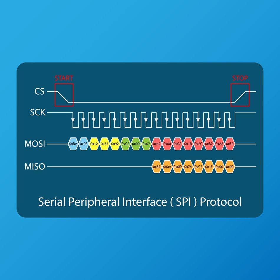 Serial Peripheral Interface Protocol
Conclusion
The Universal Asynchronous Receiver‑Transmitter (UART) protocol remains a cornerstone of serial communication in embedded and digital systems. Its simplicity, low pin count, and robust asynchronous design make it ideal for connecting microcontrollers, sensors, modules, and other devices across a wide range of applications. By converting parallel data to serial form and vice versa, a UART enables reliable point-to-point communication without the need for a shared clock, while supporting flexible data framing, parity checking, and configurable stop bits.
Throughout this guide, we explored the fundamental principles of UART, including data framing, timing, and oversampling techniques, as well as hardware architecture, such as transmitter and receiver blocks, shift registers, buffers, and error detection logic. Implementation strategies in embedded systems—including polling, interrupt-driven, and DMA-based methods—highlight how engineers can optimize throughput and CPU efficiency. We also examined configuration parameters, such as baud rate, frame format, flow control, and power considerations, which are critical for maintaining data integrity and system reliability.
Furthermore, we see that UART’s integration with different hardware interfaces, including TTL, RS‑232, and RS‑485, demonstrates its versatility across voltage levels, distances, and industrial environments. Then, applications of UART were discussed, and we concluded by comparing the UART protocol with different protocols like SPI and I2C.
Frequently Asked Questions (FAQ)
What is the difference between TTL and RS‑232 UART?
TTL (Transistor–Transistor Logic) UART operates at logic‑level voltages (3.3 V or 5 V) and uses non‑inverted signalling, making it suitable for short PCB traces. RS‑232 employs higher voltages (±3 V to ±15 V) and inverts logic levels (1 = negative voltage), allowing communication over cables up to 15 m. A level‑shifting transceiver like the MAX232 is required to convert between TTL and RS‑232.
How do I choose the right baud rate?
Select a baud rate supported by both devices and appropriate for the application’s data throughput. Common values include 9 600, 19 200, 38 400 and 115 200 bps. Consider oscillator accuracy; a total mismatch beyond 3.75 % may cause framing errors. When in doubt, choose a lower baud rate to increase tolerance.
Can UART support multi‑drop networks?
Standard UART is point‑to‑point. To support multiple devices, use RS‑485 transceivers and 9‑bit mode to include an address bit. Only the addressed device responds, enabling up to 32 nodes on a half‑duplex bus.
What is the purpose of parity in a UART frame?
Parity adds a single bit to the data frame to detect single‑bit errors. Even parity ensures that the total number of logic “1” bits is even, while odd parity ensures an odd count. If the receiver calculates a different parity than expected, it flags an error. Parity does not correct errors; higher‑level protocols should handle retransmission.
Why use hardware flow control instead of software?
Hardware flow control (RTS/CTS) uses separate lines that are not part of the data stream, allowing binary data to include any byte value without ambiguity. Software flow control (XON/XOFF) sends control characters within the data stream; if the data payload contains these characters, they must be escaped or the protocol may be misinterpreted.
What should I do when I encounter framing or overrun errors?
Framing errors often indicate mismatched baud rates or noise. Verify that both devices use the same settings, inspect the waveform with an oscilloscope, and consider reducing the baud rate. Overrun errors occur when the receive buffer is full; increasing the FIFO size, implementing flow control or using DMA can prevent data loss.
Are there alternatives to UART for high‑speed or multi‑master systems?
Yes. For higher data rates or multiple devices on a shared bus, consider synchronous protocols such as SPI (tens of Mbps) or I²C (up to 5 Mbps) or network‑oriented interfaces like CAN, LIN or USB. These protocols include bus arbitration and error checking suitable for complex systems [5].
References
[1] “Universal Asynchronous Receiver‑Transmitter (UART),” Wikipedia, 2025. [Online]. Available: Link. [Accessed: Jan. 20, 2026].
[2] “Universal Asynchronous Receiver‑Transmitter (UART) Tutorial,” Next Electronics Tutorials, 2026. [Online]. Available: Link. [Accessed: Jan. 21, 2026].
[3] J. Smith, “Understanding UART Configuration for RS232, Full‑duplex RS422, and Multi‑drop RS485,” Mosaic Industries, 2026. [Online]. Available: Link. [Accessed: Jan. 22, 2026].
[4] R. Lee, “UART (Universal Asynchronous Receiver Transmitter) Communication Protocol,” Air Supply Lab, 2026. [Online]. Available: Link. [Accessed: Jan. 21, 2026].
[5] “Serial Communication Protocols and Standards: RS232, UART, USB, Wi‑Fi,” StudyLib, 2026. [Online]. Available: Link. [Accessed: Jan. 22, 2026].
in this article
1. Introduction2. Fundamentals of UART Communication3. UART Architecture and Internal Blocks4. UART Data Framing and Timing5. Configuration Parameters and Design Considerations6. UART Implementation in Embedded Systems7. Hardware Interfaces: TTL, RS‑232, and RS‑4858. Error Detection and Handling9. Applications of UART10. Best Practices for Reliable UART DesignUART vs. Other Serial Protocols12. Frequently Asked Questions (FAQ)13. References