Powering Electric Motor Drives
Explore how electric motor drives are powered, from inverter architectures and MOSFETs to IGBTs, GaN, and SiC devices, and how each impacts efficiency, cost, and performance.

05 Feb, 2026. 7 minutes read
Some of the most popular motor types used today would not be viable without control methods based on powerful microcontrollers processing complex algorithms; for example, a permanent magnet synchronous motor (PMSM) and brushless DC (BLDC) motor both require extensive mathematical calculations to operate effectively. Microcontrollers are generally at their best when performing intricate calculations, not when delivering precise power levels. Although some microcontrollers integrate circuitry that can provide the necessary power, a dedicated power system is often required.
In this article, we will examine the architectures and components that go into powering electric motors.
Architecture
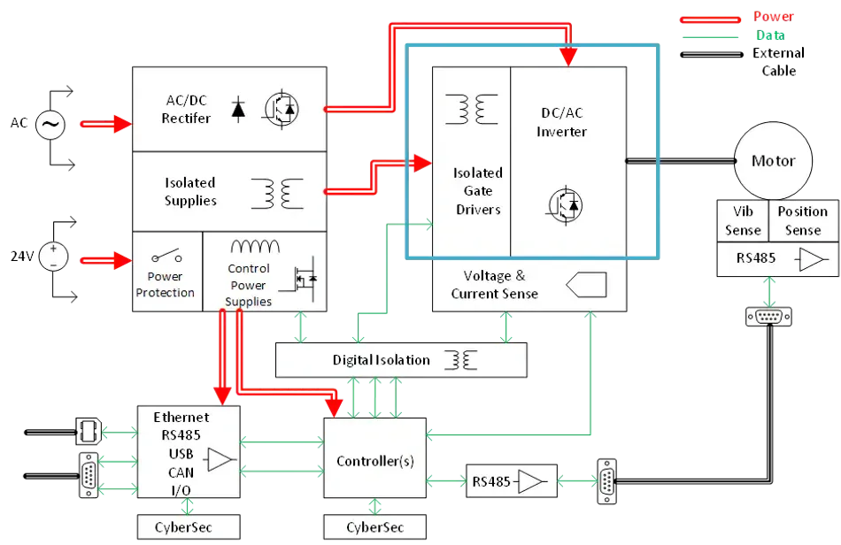
The most widely used method for delivering power to the stator coils in three-phase AC and BLDC motor control designs is to use an inverter (Figure 1). In most three-phase AC motor designs, the supply voltage is first converted to DC, and then the resulting DC signal is converted to the desired AC frequency and magnitude using pulse-width modulation (PWM).
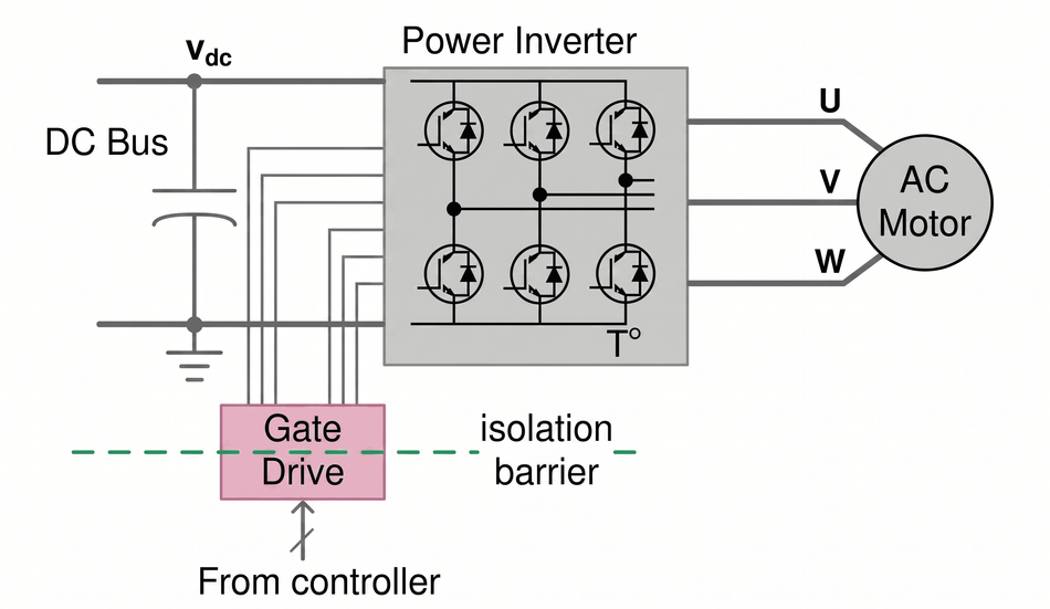
Various types of inverters can be used depending on the motor topology and number of phases. Still, the most common way to deliver the PWM signal is through a three-phase, two-level configuration (Figure 2). In this case, the inverter bridge consists of six transistors, each with a flyback diode across the transistor to protect it from sudden voltage spikes that occur when the supply current is reduced quickly from an inductive load, such as a motor. The six transistors are independently controlled by six gate drivers and are fully turned on or fully turned off at high frequency. They act as quasi-ideal switches to modulate the voltage to the stator electromagnets, recreating the PWM signal to control the motor’s speed. BLDC motors are controlled similarly, but no initial rectification is required because the input voltage is already DC.
Power Components
MOSFETs and IGBTs have traditionally been used to act as switches in inverter designs to deliver power. MOSFETs can potentially switch at frequencies up to 100kHz, but are more often used at speeds in the tens of kHz. They use a manufacturing process similar to that of the ICs that control them, enabling a single-chip solution for some lower-power applications. Other advantages of MOSFETs include high input impedance, low on-resistance, low gate drive current, ease of driving, and a wider safe operating area. These traits make MOSFETs ideal for applications requiring an energy-efficient solution for low current densities. However, as the voltage increases, the junction temperature rises, and the reverse-recovery performance of their internal diode deteriorates, leading to increased heat and switching losses.
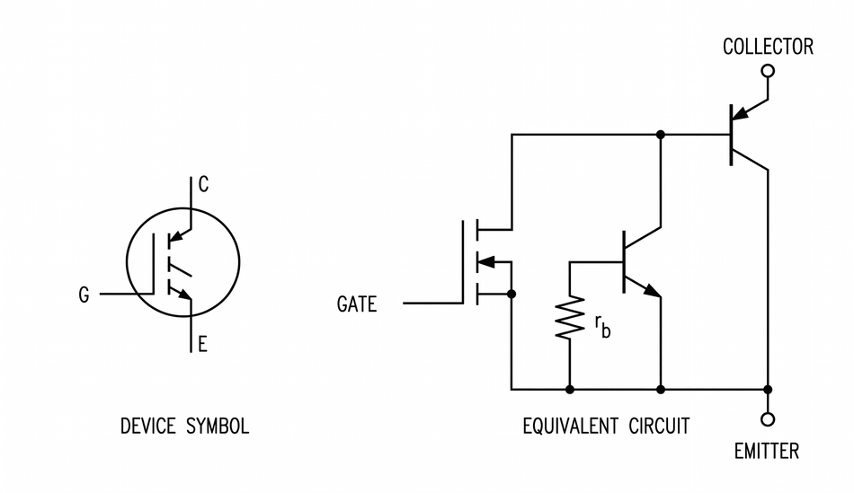
At those higher voltage and current levels, IGBTs are usually the preferred choice of switching devices. IGBTs have a similar structure to MOSFETs, but an extra P+ layer is added at the collector, making it act like a MOSFET driving a PNP transistor (Figure 3). They are easy to drive with a low-power signal and operate at around 20kHz. However, IGBT designs preclude their manufacture on a typical MOS IC process, so they lack an integrated internal reverse-recovery diode like a MOSFET. For motor-control applications, a diode must be used, either externally on the PCB or packaged as a separate die with the IGBT. External recovery diodes offer both advantages and disadvantages: they can be tailored to the specific application, but doing so adds cost to the design and requires extra PCB space.
Key Parameters
For both MOSFETs and IGBTs, current handling and peak-voltage ratings are the primary traits needed to meet the requirements of the motor’s load. After those specifications, the two devices have secondary and tertiary requirements.
The most important secondary parameters of MOSFETs are drain-source on-resistance and gate capacitance. Lower on-resistance reduces resistive losses and lowers the voltage drop during conduction, directly improving efficiency. However, it is not as straightforward as it seems. The gate capacitance determines how quickly the conductance can be switched on and off, as given by the equation I = C dV/dt. In addition to the switching frequency, it contributes to gate losses. The higher the switching frequency, the greater the losses and the lower the efficiency. A MOSFET designed to have a lower drain-source on-resistance will usually have a larger gate area, which leads to a higher gate capacitance. So, a trade-off can be achieved between the drain-source on-resistance and gate capacitance to get the best performance and lowest losses. Manufacturers almost always give an idea of the overall value as a figure-of-merit (FOM) in the datasheet using the equation FOM = drain-source on-resistance × gate charge.
For IGBTs, the on-state voltage drop is a critical specification. This drop includes both the diode drop across the P-N junction and the voltage drop across the driving MOSFET. Contrary to a pure power MOSFET, the on-state voltage drop of an IGBT does not fall below the threshold of a diode.
Selecting the right component is not just a matter of choosing the right figures from a datasheet because the parameters change during operation. Both the drain-source on-resistance of the MOSFET and the on-state voltage drop of the IGBT are affected by both temperature and current, and both types of devices are susceptible to heating during operation. The MOSFET’s voltage drop is proportional to the current, and its drain-source on-resistance increases with temperature. The voltage drop in an IGBT is similar to that of a diode, increasing with the log of the current and remaining relatively constant with temperature.
The Wide Bandgap Revolution
Until recently, silicon MOSFETs and IGBTs were the components of choice to power electric motors. Many applications remain perfectly acceptable options, but now further choices are available due to the commercialization of wide bandgap technologies. Over the last decade, gallium nitride (GaN) and silicon carbide (SiC) semiconductors have entered the market, offering performance superior to silicon transistors in almost all cases.
The bandgap is the energy required for electrons and holes to transition from the valence band to the conduction band. While silicon has a bandgap of 1.12eV, SiC and GaN have bandgaps of 3.26eV and 3.39eV, respectively. The breakdown fields of the three materials tell a similar story. SiC is 3.5MV/cm, GaN is 3.3MV/cm, and silicon is 0.3MV/cm. These figures indicate that GaN and SiC are over 10 times more capable of sustaining higher voltages. In practical terms, the two wide-bandgap materials can switch faster and withstand higher voltages for longer, making them more efficient. They can also withstand higher operating temperatures than silicon—around 600°C for SiC and 300°C for GaN, compared to only 200°C for silicon devices. Those benefits alone mean that wide-bandgap designs can deliver smaller, lighter solutions, improved performance, and easier thermal management.
Although the bandgap figures look similar for GaN and SiC, their electron mobility figures are very different and play a large part in dictating how the materials are used for power-handling applications. Electron mobility measures how fast an electron can travel through a conductor or semiconductor material when pulled by an electrical field. GaN is the fastest with an electron mobility of 2,000cm2/Vs, followed by silicon at 1,400cm2/Vs, and then SiC at 650cm2/Vs.
Those better specifications mean that GaN can switch rapidly, ten times faster than silicon MOSFETs. The very low gate capacitance of GaN designs also reduces switching losses. A great example of how GaN transistors can transform power designs is the USB charger for mobile phones. These chargers have shrunk in size, even as their power-handling capability has increased from around 11W to 70W. As such, GaN provides an ideal solution for motor applications up to 650V and 20kW that require the highest possible efficiency.
On the other hand, SiC switches a lot slower than GaN while still being faster than silicon solutions. The material offers additional power delivery benefits, such as high voltage and current handling, high thermal conductivity, and robustness. The higher switching frequencies of SiC make it preferable for designs that require high efficiency and accuracy up to around 1,200V and 200kW.
Of course, there are trade-offs required to get that better performance. Wide bandgap semiconductors are much harder to drive than MOSFETs and IGBTs, leading to increased design time and complexity. Additionally, one of the most significant advantages of using wide bandgap materials is that the faster switching allows smaller filter components to be used. However, motor applications don’t use filters extensively because motor windings can smooth the PWM signal. Even the moderate switching speeds provided by MOSFETs and IGBTs offer almost perfect waveforms. SiC and GaN transistors can also incur reverse-recovery losses during operation.
Based on initial cost, IGBTs and MOSFETs are less expensive than SiC and GaN transistors, making them a better option for many cost-sensitive applications. However, although SiC and GaN transistors are more expensive than their silicon counterparts, their higher efficiency may make them the less expensive solution over the entire application lifecycle.
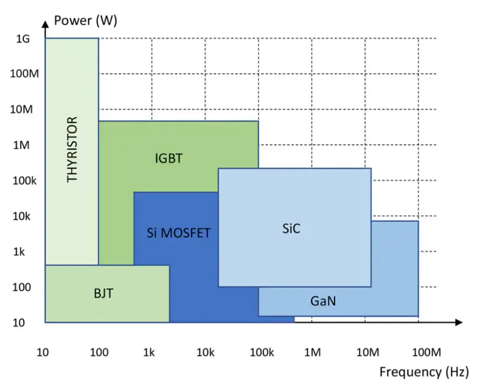
All the types of transistors we have described are suitable choices, depending on the application requirements. In fact, as shown in Figure 4, there are significant overlaps at around the 100kHz/10kW level, and all four transistor types may be viable choices. Of course, as GaN and SiC transistor technology matures, future generations of devices will likely improve performance and reduce cost. That’s not to say that IGBTs and MOSFETs will remain as they are now. For example, recently introduced trench IGBTs offer improved performance, reduced size, and better thermal performance.
Conclusion
Electric motor drives rely on more than just advanced control algorithms. They demand efficient, robust power delivery systems. Traditional silicon-based MOSFETs and IGBTs have served this role well, offering proven performance across a wide range of applications. However, the emergence of wide bandgap technologies, such as GaN and SiC, is reshaping the landscape, enabling higher switching speeds, improved thermal management, and greater overall efficiency. While these newer devices introduce design complexity and higher upfront costs, their long-term benefits in size, performance, and lifecycle efficiency make them increasingly appealing for modern motor applications. Ultimately, selecting the right solution depends on balancing voltage, current, thermal, and cost considerations.