X5R vs X7R: Comprehensive Comparison & Engineering Design Guide 2025
This guide delves into X5R vs X7R multilayer ceramic capacitors (MLCCs), explaining the physics, design trade-offs, and how to choose the right dielectric for modern digital and analog circuits.

22 Sep, 2025. 16 minutes read
SMT - Chip Ceramic Capacitors
Introduction
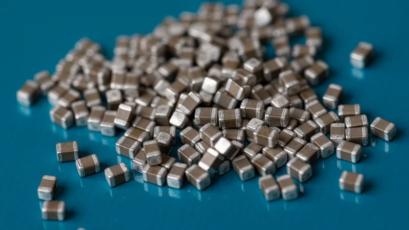
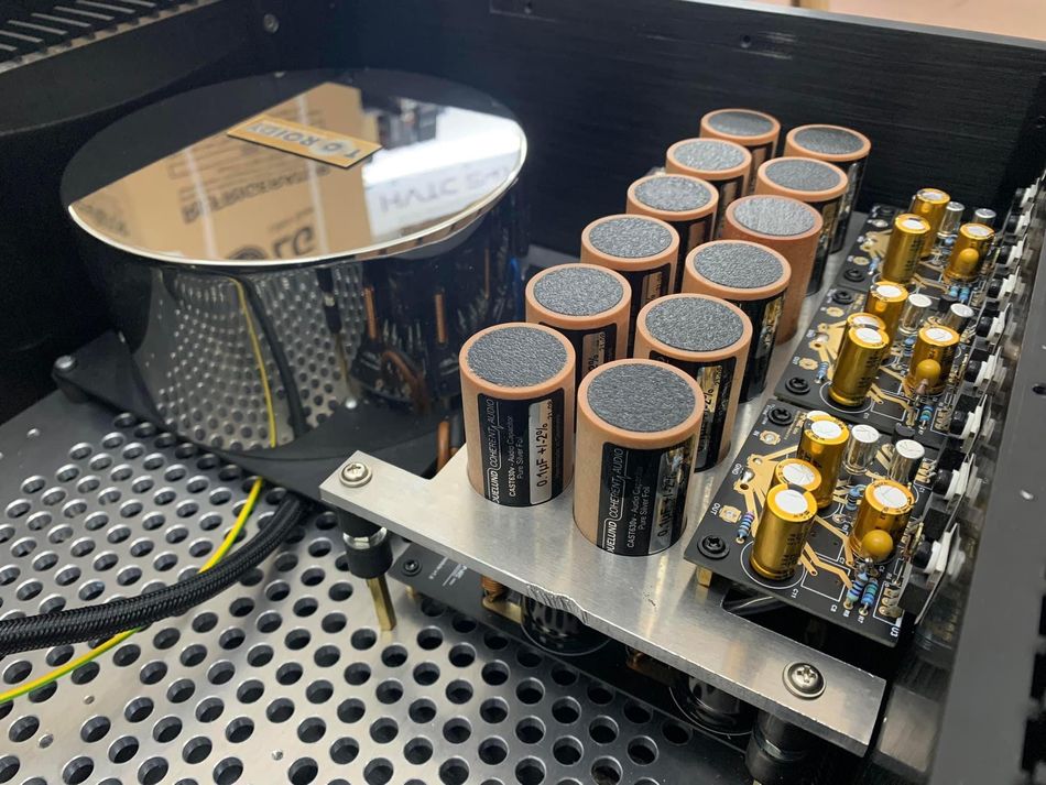
Modern multilayer ceramic capacitors (MLCCs) have revolutionised circuit design by squeezing tens of microfarads into tiny surface‑mount packages. Both X5R vs X7R belong to the Class II family of MLCCs, widely applied in decoupling, bypassing, and filtering. They are designed to deliver high capacitance in small form factors. However, their performance varies with temperature, voltage, frequency, and time.
Understanding the trade-offs in X5R vs X7R capacitors is essential; an engineer expecting a 10 µF capacitor may easily use one that behaves like 3 µF at high bias and elevated temperature. This article delves into the naming codes, physics, and practical trade‑offs of X5R vs X7R capacitors, offering quantitative guidelines, design examples, and forward‑looking insights. This helps digital design engineers, hardware engineers, and electronics students make informed choices.
Understanding the X7R and X5R
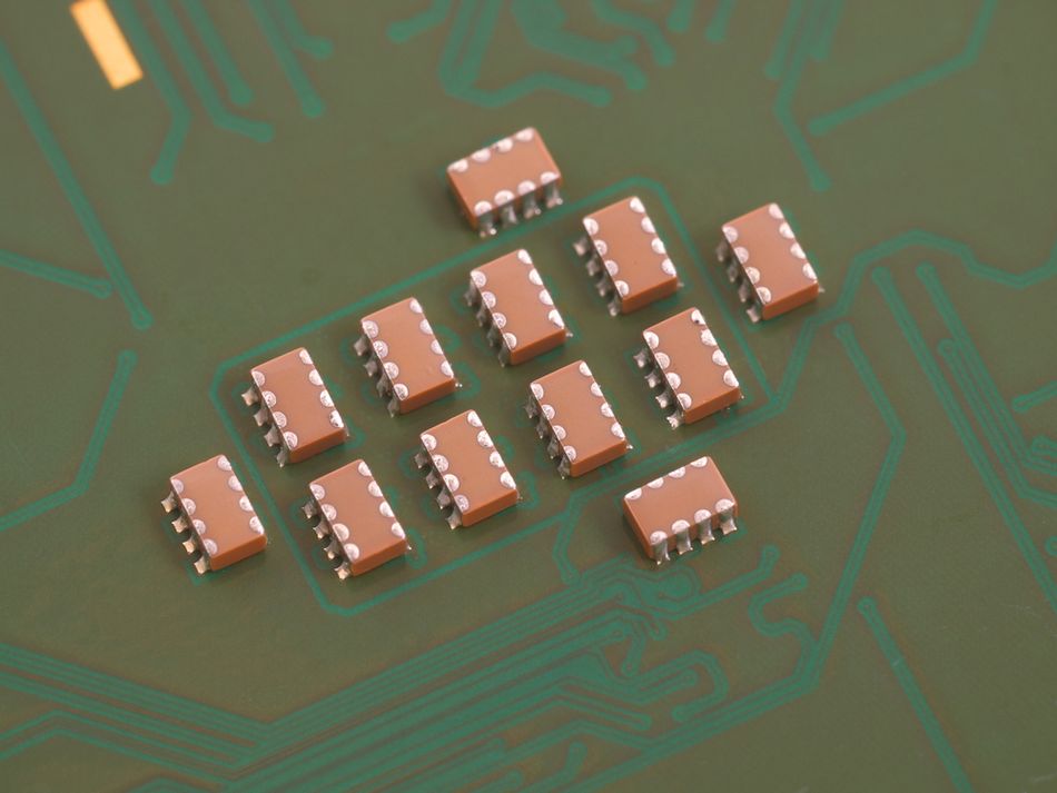
X5R and X7R belong to the Class II family of multilayer ceramic capacitors (MLCCs), widely used in decoupling and power supply applications. Both are considered general-purpose electronic components, offering a balance between capacitance value, stability, and cost.
Basics of X5R Capacitors
The X5R capacitor is one of the most widely used types of Class II dielectric in modern electronics. It offers an operating temperature range from –55°C to +85°C, making it suitable for consumer electronics, computing devices, and environments with moderate thermal stress. The "X5R" designation follows the EIA coding system, where “X” denotes –55°C as the minimum, “5” indicates a +85°C maximum, and “R” specifies a temperature coefficient of ±15%. [1]
Historically, X5R technology emerged as manufacturers like Murata, TDK, and Kemet pushed multilayer ceramic capacitors to replace bulkier electrolytic capacitors in low-voltage circuits. Their compact size and ability to deliver high capacitance values in small ceramic chip capacitors transformed PCB layouts, enabling thinner, faster, and more efficient consumer devices.
Typical capacitance values range from a few nanofarads up to tens of microfarads. However, engineers must account for DC bias effects and derating. Like, an advertised 10 µF part may drop to nearly half under applied voltage. This behavior is critical in power supply bypassing, converters, and modules, where decoupling requires reliable, effective capacitance.
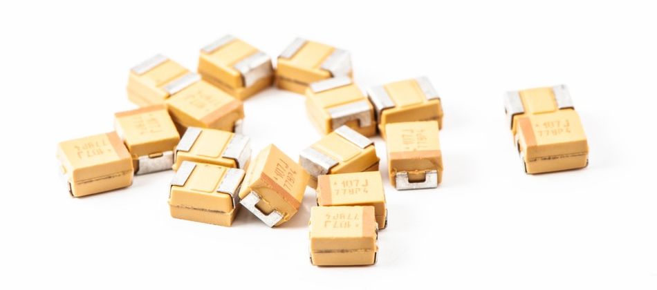
Although X5R capacitors are cost-effective and offer higher capacitance than stable dielectrics like NPO/COG, they are not ideal for high-frequency or precision circuits such as oscillators. Their moderate stability positions them between tantalum capacitors and ultra-stable dielectrics. In practice, the X5R remains a versatile choice for engineers who prioritize capacitance density and compactness over extreme accuracy.
Basics of X7R Capacitors
X7R capacitors represent the most versatile members of the Class II capacitor types, known for combining high capacitance density with a broad operating temperature range from –55°C to +125°C. Like X5R, the "X7R" designation follows EIA standards: “X” denotes –55°C, “7” indicates +125°C, and “R” specifies a temperature coefficient of ±15%. This makes them highly reliable in automotive, industrial, and aerospace systems where wide temperature swings occur.
The adoption of X7R capacitors accelerated in the 1990s as electronics demanded greater miniaturization and high stability under more challenging conditions. [2] They rapidly replaced larger tantalum and electrolytic capacitors in power supply filtering and decoupling networks. Industry leaders such as Murata, TDK, and Kemet refined the dielectric constant formulations to support high-voltage ratings, compact PCB integration, and long service life.
X7R capacitors are widely used in modules, DC-DC converters, and systems requiring consistent impedance across wide temperature characteristics. While they provide higher capacitance than Class I dielectrics, their performance still degrades with dc bias and applied voltage. Because of their durability, X7R capacitors are favored in automotive electronics, communication systems, and high-frequency filtering, where low ESR and predictable performance are vital.
In summary, X7R capacitors extend the limits of MLCCs, offering designers both capacitance value flexibility and thermal resilience across mission-critical environments.
Recommended Reading: Capacitor Polarity: Ensuring Proper Orientation for Optimal Performance
Theoretical Foundations Reveal Critical Differences in X5R vs X7R
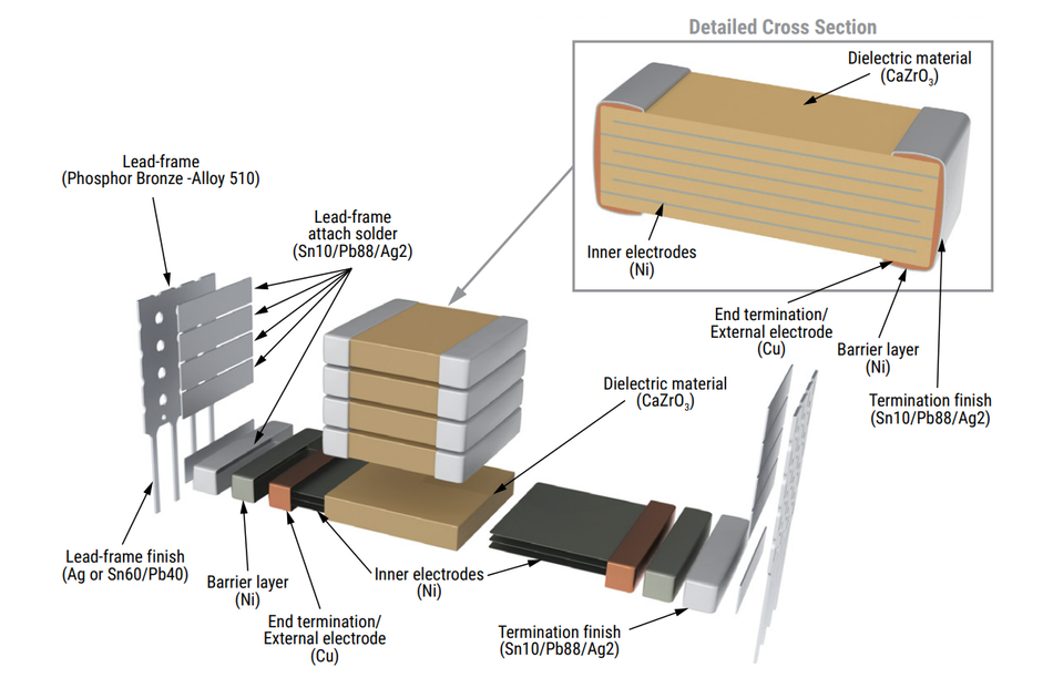
X5R and X7R devices are classified as Class‑2 dielectrics because they use ferroelectric barium‑titanate ceramics with high relative permittivity.
The relative permittivity (2,000 – 4,000) yields large capacitance in a small volume, but the ferroelectric material exhibits nonlinear behaviour with temperature and electric field.
Temperature Coefficient of Capacitance (TCC)
Temperature affects the relative permittivity of barium titanate. The capacitance variation with temperature can be approximated by:

Where α and β are empirical coefficients. For X7R capacitors, α ≈ −400 ppm/°C with minimal β, giving a relatively flat response up to 125°C. The X5R capacitors follow the same model but are guaranteed only to 85°C; above this, drift may exceed ±15%.
Design Tip: Choose X7R for environments above 85°C, such as automotive or industrial electronics.
Dielectric Constant vs Stability
The capacitance is defined as:

where A is the electrode area and t is the dielectric thickness. The ceramics with high relative permittivity allow compact ceramic chip capacitors with higher capacitance. However, operation near the Curie point increases temperature sensitivity, reducing long-term stability. Class I dielectrics such as C0G (NP0) have low relative permittivity ≈ 30 but maintain excellent stability, making them preferable for oscillators and precision timing circuits.
Voltage Coefficient of Capacitance (VCC)
Ferroelectric MLCCs exhibit a strong voltage dependence. When a DC voltage is applied, the electric field aligns dipoles and reduces incremental permittivity. This DC bias effect can shrink capacitance by 10–90% at rated voltage.
Depending on the dielectric formulation, X5R and X7R capacitors can lose more than 70% of their rated capacitance under DC bias. The derating voltage is therefore crucial: selecting a capacitor with a rated voltage at least twice the operating voltage keeps the electric field low and minimizes capacitance loss.
Aging
Ferroelectric domains gradually realign over time, resulting in a logarithmic decrease in capacitance with age. X5R and X7R lose approximately 2.5% of capacitance per decade hour. This means a freshly manufactured 22 µF capacitor may drop to about 17 µF after 5,000 hours (~208 days). [3] The process is reversible by heating above the Curie temperature (~125 °C), but this is impractical for most applications. Designers should oversize capacitance by 20–30% to account for ageing over the product lifetime.
Piezoelectric (Microphonic) Behavior
Class‑2 dielectrics are piezoelectric: mechanical stress produces voltage and vice versa. X5R/X7R capacitors can act as tiny microphones or speakers, converting sound into electrical noise and vice versa. In audio circuits, use Class‑1 C0G capacitors or mechanically isolate Class‑2 parts to prevent audible “singing.”
Both X5R and X7R capacitors use barium‑titanate dielectrics with high permittivity, delivering high capacitance density but exhibiting significant voltage dependence, aging, and piezoelectric behaviour.
Recommended Reading: Decoupling Capacitors: Mastering Power Integrity in Electronic Design
Analysis and Design Techniques Leveraging Voltage-Dependent Characteristics
Derating Guidelines and DC Bias
Class II MLCCs such as X5R and X7R exhibit significant dc bias effects, often losing up to 90% of their nominal capacitance value at rated voltage. To mitigate these losses, designers should follow established derating practices:
Select a Higher Voltage Rating: Choose parts rated for at least 2× the operating DC voltage. For example, use ≥10 V capacitors on a 5 V rail to lower the electric field stress.
Use Parallel Capacitors: Distributing the required capacitance across multiple devices reduces energy density and improves bias performance.
Account for Temperature Derating: Above 80 °C, X5R capacitors show accelerated drift; X7R capacitors or additional derating should be used in high-temperature environments.
Include an Aging Margin: Oversize designs by 20–30% to compensate for long-term capacitance decay.
Leverage Vendor Tools: Simulation platforms such as Kemet K-SIM and Murata SimSurfing provide absolute capacitance vs voltage/temperature plots to evaluate worst-case conditions.
Calculating Energy Density
Bias sensitivity correlates more strongly with energy density than the dielectric label. The energy per unit volume is:

where C is the effective capacitance, V is the applied voltage, and L, W, and T are the package dimensions. When D approaches 10 µJ/mm³, bias effects and fatigue become significant.
ESR, ESL, and Resonance
MLCCs behave as RLC networks. ESR and ESL depend more on package geometry than dielectric type. Small packages (0402) offer low ESR but higher ESL; larger formats (1210) exhibit the opposite. The series resonant frequency (SRF) is approximated by:

where L is inductance (~0.5–1 nH for 0402) and Ceff is effective capacitance after derating. For example, a 1 µF 0402 X5R derated to 0.6 µF and using L ≈ 1 nH yields SRF ≈ 205 MHz. Multiple capacitors of different sizes placed in parallel create staggered resonances, flattening impedance across a broad frequency band.
Step-by-Step Design Example
Consider an MCU drawing 200 mA transients in 50 ns, with an allowable ripple of 50 mV. The required decoupling capacitance is:

The process will be followed as:
Select Voltage Rating: The MCU runs at 3.3 V → choose capacitors rated for at least 6.3 V.
Choose Dielectric: Because the design will operate up to 95°C, select X7R to maintain capacitance beyond 85°C.
Determine Quantity and Size: Two 1 µF 0805 X7R capacitors rated at 10 V provide 2 µF nominal. Assuming 30% DC derating and ±15 % TCC, each yields ~0.6 µF effective; together they provide ~1.2 µF. Add a 0.1 µF 0402 C0G capacitor for high‑frequency decoupling.
Simulate: Use K‑SIM to verify capacitance vs bias at 3.3 V and temperature profile; ensure the combination meets ripple requirements.
Layout: Place the 0.1 µF capacitor closest to the MCU supply pin, followed by the 1 µF capacitors, minimizing loop area.
This layered approach ensures robust decoupling under real-world conditions.
Quantitative Metrics and Cost Comparison
| Metric | X5R (Typical 0805, 10 µF, 6.3 V) | X7R (Typical 0805, 10 µF, 10 V) |
| Temperature Range | X5R (Typical 0805, 10 µF, 6.3 V) | X7R (Typical 0805, 10 µF, 10 V) |
| Capacitance Change vs Temperature | −55°C to +85°C | −55 °C to +125°C |
| Capacitance Change vs Temperature | ±15% | ±15% |
| DC Bias (50% rated voltage) | –40% to –50% | –30% to –45% |
| Aging Rate | ≈ 2.5% per Decade Hour | ≈ 2.5% per Decade Hour |
| ESR @100 kHz | ≈ 5 mΩ | ≈ 5 mΩ |
| Cost (€/1,000 pcs) | 0.08–0.12 | 0.10–0.15 |
| Typical Applications | Consumer Electronics, Low‑Temperature Decoupling | Automotive, Industrial, High Temperature Decoupling |
While X7R offers a higher temperature rating and marginally lower DC bias sensitivity, both types experience significant capacitance loss under bias. It is always better to verify the effective capacitance using simulation or measurement.
Recommended Reading: Capacitors in Series: Theory, Design Considerations and Practical Implementations
Typical Applications Span from Power Supplies to High-Frequency RF
Power Supply Decoupling
MLCCs are ubiquitous in voltage regulators, DC–DC converters, and microprocessor power rails. A typical buck converter might use a 22 µF X7R as the bulk output capacitor, supplemented by 1 µF and 0.1 µF capacitors to handle different frequency ranges.
Replacing tantalum capacitors with parallel X7R MLCCs reduces equivalent series resistance (ESR) to below 50 mΩ, improving transient response by 15–30% and reducing board area by 40%. [4] For temperatures under 80°C, cost‑sensitive designs may use X5R; otherwise, X7R is preferred.
RF and High-Frequency Circuits
In RF front‑ends, decoupling capacitors must present low impedance at hundreds of megahertz. While X5R/X7R have higher dielectric loss (tan δ ≈ 0.015) than C0G, they provide high capacitance density in small packages (0201 or 0402). The examples include 1–10 nF X7R capacitors in Bluetooth and Wi‑Fi matching networks. For resonant or filter sections, Class‑1 capacitors (C0G) offer higher Q and stability; X7R/X5R are used for bypassing and energy storage.
Industrial and Automotive Systems
Automotive electronics experience ambient temperatures up to 105°C under the hood. X7R capacitors are rated to 125°C, making them suitable for engine control units, transmission modules, and ADAS sensors. For interior modules, such as infotainment systems and LED drivers, X5R may be sufficient if temperatures remain below 85°C. When designing for harsh environments, use AEC‑Q200 qualified parts and account for wide temperature swings.
Medical and Aerospace
Medical devices and avionics demand reliability and long life. The aging of Class‑2 MLCCs (~2.5% per decade hour) requires oversizing and careful derating. Designers often pair X7R capacitors for bulk energy storage with C0G capacitors for timing circuits where stability matters. In implantable devices, packaging considerations (hermetic sealing) and low leakage currents favour tantalum or film capacitors for main energy storage, with X7R MLCCs used for high‑frequency decoupling.
Energy Harvesting and Wireless Power
Advanced uses of X7R include resonant wireless power transfer. At 6.78 MHz (Qi standard), arrays of derated X7R capacitors can form the resonant tank, delivering high capacitance density while maintaining acceptable quality factor (Q). However, dielectric heating due to the loss tangent must be managed; designers should simulate the thermal rise under the expected current.
From consumer devices to aerospace, X5R and X7R capacitors enable reliable performance across diverse systems. Their balance of capacitance density, stability, and cost ensures continued dominance in modern electronics.
Recommended Reading: RF PCB: Design, Materials, and Manufacturing Processes
Integration with Emerging Technologies Enables Novel Benefits
GaN and SiC Power Electronics
Wide‑bandgap semiconductors switch at hundreds of kilohertz to megahertz. They require capacitors with low ESR and ESL. X7R/X5R MLCCs in copper/nickel electrode structures suit these applications, serving as snubbers, resonant tank capacitors, and decouplers. Using an X7R array can improve converter efficiency by 1–2% compared with film capacitors. However, at high frequencies the dielectric loss of Class‑2 materials becomes significant; mixing X7R with C0G or polypropylene capacitors yields optimal performance.
Embedded Systems and IoT
Modern microcontrollers integrate multiple voltage domains: core, I/O, analog, and RF. Embedding MLCCs within the PCB stack reduces loop inductance and improves electromagnetic compatibility (EMC). X7R films with high relative permittivity can be laminated into the substrate, providing distributed capacitance (10 nF/in²). This technique is used in smartphones and IoT devices to maximise board density. X5R may be used for low‑temperature domains, but X7R is preferred when reliability across temperature is required.
3-D Packaging and Integrated Passives
System‑in‑package (SiP) and 3‑D integrated circuits combine active and passive components in a single module. Thin‑film X7R capacitors deposited on silicon interposers offer lower ESR/ESL and better matching with high‑speed transceivers. However, their capacitance per area (~100 nF/mm²) is lower than that of discrete MLCCs; they serve as decoupling for high‑frequency noise rather than bulk storage. Designers often place discrete X5R/X7R capacitors nearby to supplement the integrated passives.
Pitfalls and Mitigation
Class‑2 capacitors can produce audible noise due to piezoelectric coupling. Rapid voltage transitions cause mechanical vibrations, resulting in whining or buzzing. Spreading capacitors across the board, using smaller packages, or mixing in C0G capacitors can reduce the effect. In high‑switching‑frequency GaN circuits, the vibration may couple into the board; mechanical dampening or adhesive may be necessary.
X5R and X7R capacitors continue to evolve alongside GaN, SiC, and advanced packaging. Their adaptability ensures reliable performance in next-generation electronics, from IoT to aerospace applications.
Recommended Reading: How are Semiconductors Made? A Comprehensive Guide to Semiconductor Manufacturing
Modern Software Tools Revolutionize X5R vs X7R Implementation
The complex behavior of MLCCs extends far beyond static datasheet values. Effective design now relies on simulation tools that capture capacitance variation with DC bias, operating temperature, frequency, and long-term aging. The key tools include:
K-SIM (Kemet, 2024) – Models capacitance, ESR, and bias-temperature effects. Includes an energy-density calculator and aging predictor, with direct SPICE model export for power supply and converter design.
SimSurfing (Murata, 2024) – Provides S-parameters and full impedance curves up to gigahertz frequencies. Enables combining multiple capacitors to optimize parallel networks and flatten impedance response.
LTspice (Analog Devices, 2024) – A general-purpose circuit simulator supporting MLCC models with voltage coefficient of capacitance (VCC) and aging effects. Useful for transient and frequency response analysis in PCB-level designs.
Keysight ADS (Keysight, 2025) – High-frequency simulation suite integrating EM solvers with circuit modeling. Captures PCB parasitics and MLCC interaction at RF, essential for high-frequency and RF decoupling analysis.
Using these tools, engineers can directly compare X5R vs X7R performance in realistic conditions. For example, K-SIM may show that a 10 µF 0805 X7R retains ~70% of nominal capacitance at 5V bias, while an equivalent X5R may drop to ~60%. In precision analog systems, this 10% difference can determine whether the lower cost of X5R outweighs potential ripple and stability issues.
Best Practices Address Common Implementation Pitfalls
Voltage Derating: Choose capacitors rated at least twice the maximum operating voltage. For long‑life or safety‑critical systems, consider 3× derating. This reduces DC bias stress and slows fatigue.
Temperature Derating: Avoid using X5R above ~80 °C. For ambient temperatures beyond this, select X7R or higher‑temperature dielectrics (X8R or X8L). In automotive under‑hood conditions, ensure capacitors are AEC‑Q200 qualified.
Allow for Aging: Increase capacitance by 20–30 % to compensate for the logarithmic loss (~2.5 % per decade hour). For 10‑year products, assume four decades of aging (~10 % loss) and design accordingly.
Use Multiple Values and Packages: Combine different capacitances and package sizes to spread resonances and reduce impedance peaks. For example, a combination of 10 µF (0805), 1 µF (0603), and 0.1 µF (0402) covers frequencies from kilohertz to hundreds of megahertz.
Mitigate Microphonics: Class II dielectrics exhibit piezoelectric effects, which can inject noise into sensitive analog or audio paths. Substitute with C0G capacitors, film capacitors, or mechanically isolate X5R/X7R parts.
Follow Proper Soldering Profiles: Excessive reflow temperatures can degrade dielectric properties. Adhere to manufacturer reflow profiles (typically 245–250 °C peak) and avoid mechanical stress during cool‑down.
Verification should include measuring effective capacitance under bias with an LCR meter, testing at elevated temperature in a thermal chamber, and evaluating acoustic noise if relevant. Compliance with standards such as AEC‑Q200 (automotive MLCCs) and IEC 60384-14 (safety capacitors) ensures robustness.
Recent Developments and Advanced Applications of MLCC Technology
Breakthroughs in Dielectric Materials
Research from 2024–2025 has introduced new dielectric formulations aimed at reducing voltage dependence and expanding operating temperature capability.
X8L Capacitors now operate from −55 °C to +150 °C with ±15% tolerance, bridging the gap between traditional X7R capacitors and higher-temperature dielectrics. [5]
Ceralink Capacitors, built from antiferroelectric materials, exhibit less than 10% capacitance loss up to 400 V, making them ideal for power inverters.
In parallel, lead-free relaxor ferroelectrics such as bismuth sodium titanate (BNT) and potassium sodium niobate (KNN) are being developed as environmentally sustainable alternatives to barium titanate.
Advances in Packaging and Integration
Progress in packaging has enabled integrated passive devices on glass substrates, providing high-Q decoupling near high-speed transceivers. Vendors are also pushing manufacturing boundaries by stacking more layers and reducing dielectric thickness below 1 µm while adopting copper electrodes. These strategies improve volumetric efficiency without sacrificing reliability, though they may require updates to traditional derating guidelines. Designers should rely on current datasheets and simulation models to reflect these new behaviours.
Sophisticated Applications Beyond Decoupling
Innovative engineers are leveraging X5R and X7R capacitors in advanced roles. In wireless power transmitters operating at 6.78 MHz, arrays of 4.7 µF X7R capacitors in series provide high voltage capability while sustaining high capacitance density. Simulations show efficiency above 90% with an acceptable quality factor (Q ≈ 20) when thermal rise is managed.
In piezoelectric energy harvesting, the intrinsic piezoelectricity of X7R is exploited by stacking layers, yielding up to 8% higher harvested power compared with conventional methods. In 5G millimetre-wave front-end modules, embedded X7R capacitors integrated into organic packages reduce insertion loss by localising decoupling, though at 28 GHz, designers often combine them with thin-film capacitors for matching networks.
Quantitative Metrics for Engineering Decisions
Selecting between X5R vs X7R often requires balancing temperature rating, voltage derating, stability, cost, and physical size. A weighted decision matrix can guide trade-offs:

S(T): Normalized temperature rating
S(V): Voltage derating factor
S(C): Inverse cost
S(E): Energy density performance
S(A): Aging tolerance
For example, an automotive design needing 10 µF at 5 V and 105 °C might compare X7R (10V, 0.12 €/piece) with X5R (6.3V, 0.09€/piece). Although X5R is cheaper, its inadequate temperature rating lowers its score, justifying the higher investment in X7R for reliability.
Future Directions: Integrating Artificial Intelligence and Sustainable Materials
AI-Assisted Capacitor Selection
Machine learning is entering EDA tools. By 2027, expect AI algorithms to analyse supplier data and circuit requirements, automatically recommending optimum capacitor mixtures. These tools will factor in voltage derating, energy density, aging, and cost. They may also suggest layout strategies that minimize ESL and ESR, further improving decoupling performance.
Sustainable Dielectrics
Regulatory pressure is driving a shift toward eco‑friendly materials. Lead‑free ceramics like BNT and KNN offer high permittivity while reducing environmental impact. Early prototypes show energy densities comparable to X7R but with reduced piezoelectric noise. Commercial adoption could begin by 2028.
Integration with Energy Storage
The power electronics converge with energy storage (e.g., EV traction inverters and renewable micro‑grids), so the capacitors must handle higher voltages and temperatures. Hybrid solutions combining MLCC layers with thin-film polymer or graphene may offer a capability of over 100 °C and improved lifetime. Standards like X8L (−55 °C to +150 °C) and X8R (−55 °C to +150 °C with ±15 % tolerance) are emerging, supporting 800 V battery packs and high‑temperature motor drives. Expect widespread availability of such capacitors by 2026–2027.
Engineers should anticipate rapid change in capacitor technology. The traditional choice of X5R vs X7R will be increasingly influenced by AI-driven design, eco-friendly, sustainable dielectrics, and integration with high-power energy storage. Staying current with materials science and EDA innovations will be essential for future-ready designs.
Recommended Reading: How Advanced Chipsets Fuel the 5G Revolution?
Conclusion
The comparison of X5R vs X7R reveals trade-offs between temperature capability, capacitance stability, and cost efficiency. Engineers must evaluate DC bias, aging, and temperature coefficient effects, not just nominal datasheet values. Modern simulation tools and derating practices ensure capacitors perform reliably under real-world stress conditions. Emerging technologies, including X8R dielectrics, AI-assisted selection, and sustainable materials, promise improved performance and environmental benefits. In demanding applications, X7R capacitors provide broader temperature tolerance, while X5R may suit cost-driven consumer devices. Future designs will increasingly integrate MLCCs with advanced packaging and hybrid energy storage. Staying informed ensures engineers select capacitors that balance performance, longevity, and sustainability in next-generation electronic systems.
Frequently Asked Questions (FAQ)
Q. Why do X5R and X7R capacitors lose capacitance under DC bias?
A. Class‑2 dielectrics contain ferroelectric domains that align under an electric field. As DC voltage increases, dipoles become saturated and the incremental permittivity drops, reducing capacitance. Capacitance loss can reach 70–90% at the rated voltage. Derating voltage and using parallel capacitors mitigate this effect.
Q. Is X7R always better than X5R?
A. Not always. X7R extends the temperature range to 125 °C and typically shows slightly less capacitance loss under bias, but it costs more and still suffers the same aging and piezoelectric issues. For consumer products operating below 80 °C, X5R may provide adequate performance at a lower cost. In high‑temperature or safety‑critical designs, X7R’s extra margin is worth the price.
Q. How should I account for aging in my design?
A. X5R and X7R capacitors lose about 2.5% per decade hour. For 10-year products (~4 decades), expect a ~10% loss. Oversize the capacitance by 20–30%, and select voltage ratings and packages that leave margin for future drift. Some designers “re‑age” capacitors by heating them above 125 °C to reset the dielectric, but this is rarely practical in production.
Q. Does dielectric type affect high‑frequency performance?
A. The ESR and ESL of MLCCs are dictated primarily by package size and layout, not by whether they are X5R or X7R. Both types share similar intrinsic losses. Smaller packages (0402, 0201) reduce ESL and push resonance to higher frequencies but may suffer greater bias sensitivity. Combining different sizes in parallel offers a wide impedance bandwidth.
Q. Can I mix X5R and X7R in the same circuit?
A. Yes. Combining dielectrics and package sizes spreads resonant frequencies and balances cost, size, and stability. Ensure each capacitor operates within its rated temperature and voltage limits. In mixed environments, place X7R near hotter components and X5R near cooler or cost‑sensitive areas.
Q. Do Class‑2 capacitors generate audible noise?
A. Yes. X5R and X7R exhibit piezoelectric behaviour; fast voltage changes can cause mechanical vibration and audible “singing.” To minimize noise, distribute capacitors across the PCB, use smaller packages, or mix in C0G capacitors, especially in audio or precision analog circuits.
Q. Are there alternatives to X5R and X7R for high‑temperature applications?
A. Emerging standards like X8R and X8L extend the temperature range to +150 °C with ±15 % tolerance. The antiferroelectric capacitors such as Ceralink provide lower capacitance loss at high voltage, making them attractive for power inverters. However, they are currently more expensive and available in limited sizes.
References
[1] ECIA. EIA Standards and Codes - Hand Book [Cited 2025 September 20] Available at: Link
[2] MDPI. Reliability of X7R Multilayer Ceramic Capacitors During High Accelerated Life Testing (HALT) [Cited 2025 September 20] Available at: Link
[3] EDN. Class 2 Ceramic Capacitors — Can You Trust Them? [Cited 2025 September 20] Available at: Link
[4] TDK. Replacing Electrolytic Capacitor with MLCC, Revised Guide [Cited 2025 September 20] Available at: Link
[5] KYOCERA. High Temperature - X8R/X8L Dielectric [Cited 2025 September 20] Available at: Link
in this article
1. Introduction2. Understanding the X7R and X5R3. Theoretical Foundations Reveal Critical Differences in X5R vs X7R4. Analysis and Design Techniques Leveraging Voltage-Dependent Characteristics5. Typical Applications Span from Power Supplies to High-Frequency RF6. Integration with Emerging Technologies Enables Novel Benefits7. Modern Software Tools Revolutionize X5R vs X7R Implementation8. Best Practices Address Common Implementation Pitfalls9. Recent Developments and Advanced Applications of MLCC Technology10. Future Directions: Integrating Artificial Intelligence and Sustainable Materials11. Conclusion12. Frequently Asked Questions (FAQ)13. References