Motor Controller: Types, Design Considerations, Control Strategies, and Selection for Engineers
This article provides a comprehensive overview of motor controllers, covering definitions, types, control strategies, design considerations, selection guidelines, and emerging trends.

Last updated on 22 May, 2026. 12 minutes read
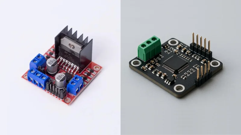
Dual, H-Bridge DC Motor Controller Board vs Motor Driver
Key Takeaways
Motor controllers are the interface between power electronics and electric motors; they start, stop, reverse direction, regulate speed and torque, and provide protection.
Controller types are customised to motor and application: DC controllers use PWM and H-bridge circuits, AC controllers use variable-frequency drives, universal motors use phase-angle or chopper control, and servo/stepper controllers incorporate feedback for precision.
Control strategies include open-loop PWM for simple speed control, vector control/FOC for high-performance brushless motors, and V/F control for AC induction motors; each has trade-offs in torque response, efficiency and required sensors.
Selecting a motor controller requires matching voltage, current and horsepower ratings, choosing appropriate control algorithms and communication interfaces, and considering protection features and electromagnetic compatibility.
Emerging trends include sensorless field-oriented control, integrated smart drivers with communication protocols (CAN, RS-485, SPI), and advanced digital power conversion that improve efficiency and simplify integration.
Introduction
In modern electromechanical systems, the motor controller plays a critical role in regulating the operation of electric motors across industrial automation, robotics, transportation, and consumer electronics. The motor controller manages key parameters such as speed, torque, direction, and startup behavior by controlling the electrical input to the motor. By precisely adjusting voltage, current, and switching sequences, the motor controller ensures stable performance, improved energy efficiency, and protection of the motor and connected equipment.
For design engineers and technical decision-makers, selecting and configuring the right motor controller is crucial to achieving performance, efficiency and reliability in mechatronic systems. Different controller architectures support various motor technologies, including brushed DC motors, brushless DC motors, stepper motors, and AC induction motors. This article provides a comprehensive overview of motor controllers, covering definitions, types, control strategies, design considerations, selection guidelines, and emerging trends.
Definition and Function of a Motor Controller
The motor controller is any device or system that coordinates the performance of an electric motor. It may include manual or automatic means for starting and stopping the motor, selecting forward or reverse rotation, regulating speed, limiting torque, and protecting against overloads and faults.
Depending on the motor type — such as a DC Motor, AC Motor, Brushless DC Motor (BLDC), or Induction Motors — the motor controller may use solid-state components. [2] MOSFETs, microprocessor-based circuits, or dedicated driver modules manage power delivery and implement advanced speed control strategies.
Typical functions of a motor controller include the following:
Start/Stop Control - The controller enables controlled motor startup and shutdown to avoid mechanical shock.
Direction Control - The controller switches supply polarity or phase sequence to reverse motor rotation. H-bridge circuit accomplishes this for DC motors.
Speed Regulation - Controllers adjust the voltage, current or frequency applied to a motor to set rotational speed.
Torque Limiting - Current-sensing circuits or closed-loop algorithms ensure that motor torque does not exceed design limits.
Protection and Diagnostics - Overcurrent, overvoltage, short-circuit, and thermal protection safeguard the motor and electronics.
Recommended Reading: H-Bridge Motor Control: A Complete Guide for Engineers 2025
Types of Motor Controllers
DC Motor Controllers
DC motor controllers are widely used due to the simplicity and responsiveness of the brushed DC motor design. These controllers regulate motor performance by adjusting the voltage or current delivered to the armature, enabling accurate speed control, position control, and torque management.
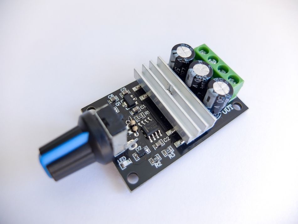
One of the most common techniques used in DC motor control is pulse-width modulation (PWM). In this method, the controller rapidly switches the power supply on and off, producing an average voltage proportional to the duty cycle. This approach improves energy efficiency and enables smooth variable-speed operation.
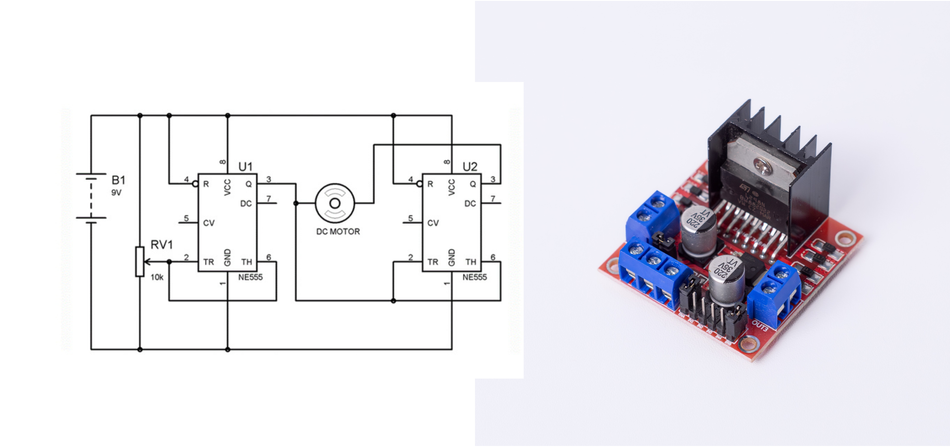
The direction control in DC motors is typically implemented using an H-Bridge circuit comprising four switching devices, often MOSFET transistors. The H-bridge allows the controller to reverse current flow through the motor, enabling forward and reverse rotation as well as dynamic braking.
Brushless DC and Universal Motor Controllers
Brushless DC (BLDC) motors eliminate mechanical commutation and use electronic commutation instead. The controllers detect rotor position using Hall sensors or back-EMF and commutate the stator windings accordingly.
Basic trapezoidal drive applies square wave excitation with 120 degree conduction, while more advanced sinusoidal drive modulates the currents to reduce torque ripple. [3] For high-performance applications, field-oriented control (FOC) transforms the three-phase currents into a rotating d-q reference frame, decoupling torque and flux.
The universal motors (series-wound motors used in appliances) operate on an AC or DC supply and rely on mechanical commutation. Phase-angle control using a TRIAC adjusts the conduction angle of the AC waveform to control speed. Alternatively, PWM chopper control rectifies the AC supply, then uses a MOSFET chopper to regulate voltage.
AC Motor Controllers (Variable-Frequency Drives)
Controllers for AC motor systems are widely used in industrial automation, particularly with induction motors. The variable-speed drive, commonly known as a variable-frequency drive (VFD), controls motor speed by adjusting the frequency and voltage supplied to the motor.
In a typical VFD architecture, incoming AC power is first rectified into DC using a rectifier and filtering stage. The DC voltage is then converted back into AC using a transistor-based inverter. By adjusting the switching pattern of the inverter, the controller produces AC output at variable frequencies and amplitudes.
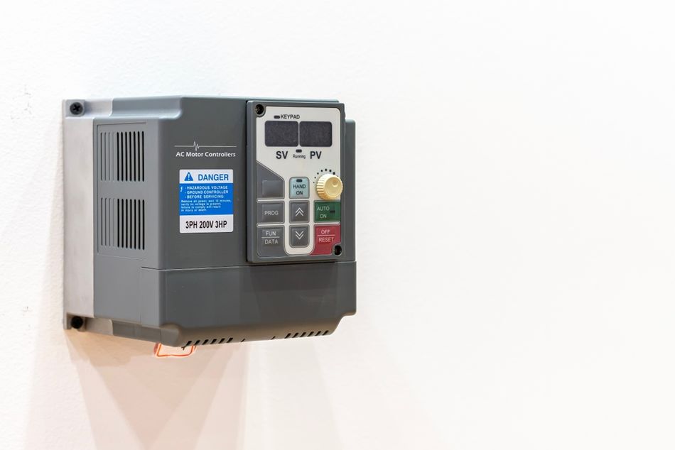
Maintaining a constant voltage-to-frequency ratio ensures that motor magnetic flux remains stable and torque capability is preserved. VFD-based motor control systems improve energy efficiency, reduce mechanical stress during acceleration, and support regenerative braking in many industrial applications.
Servo Motor Controllers
Servo motors are widely used in high-precision motion control systems that require accurate positioning and dynamic response. The servo system typically includes the motor, mechanical gearing, encoders, and a dedicated servo controller that operates using closed-loop feedback.
The servo controller continuously compares the commanded position, speed, or torque with feedback signals from the encoder. Control algorithms, most commonly a PID controller, adjust motor drive signals in real time to minimize error and maintain stable operation.
Servo controllers are frequently integrated with industrial control systems, including PLC platforms and advanced automation networks. The communication protocols, such as CANopen and EtherCAT, allow synchronized multi-axis operation, essential in robotics, CNC machines, and automated manufacturing equipment.
Stepper Motor Controllers
Stepper motors operate by moving in discrete angular increments, making them ideal for open-loop positioning systems. The stepper motor driver or controller sequences electrical signals to the motor windings, causing the rotor to move in controlled steps.
Typical stepper motors have step angles of 1.8 degrees, resulting in 200 steps per revolution. Modern controllers use microstepping techniques to divide each step into smaller increments, improving motion smoothness and reducing vibration.
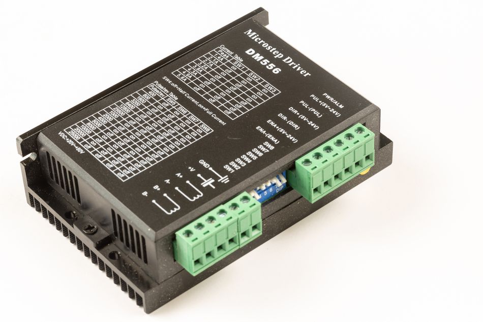
Stepper motor controllers are commonly used in automation, precision instruments, and positioning systems where moderate torque and accurate positioning are required without complex closed-loop feedback.
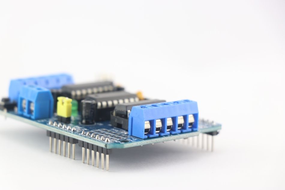
Hybrid and Intelligent Controllers
Modern motor control systems increasingly combine multiple technologies into integrated intelligent controllers. These advanced controllers incorporate microcontrollers, driver modules, current sensing circuits, and communication interfaces such as USB, SPI, I²C, and CAN.
The smart controllers may also integrate voltage regulators, protection circuits, and diagnostic capabilities for overload protection and current limiting. In embedded systems, platforms such as Arduino or other microcontroller boards can serve as development environments for custom controller designs.
By combining solid-state switching devices, sensor feedback, and programmable control logic, intelligent motor controllers enable highly efficient, adaptable, and scalable solutions for modern automation, robotics, and industrial motion control applications.
Recommended Reading: Stepper vs Servo Motors: Mastering Motor Selection for Precision Engineering
Control Strategies
The performance of a motor controller largely depends on the control strategy used to regulate the electric motor. Different motor control algorithms are designed to optimize speed control, torque response, and energy efficiency for specific motor types.
The control strategies vary in complexity, sensor requirements, and microcontroller processing demands. The table below summarizes common motor control algorithms used in modern control systems.
| Control Algorithm | Motor Types | Torque Controllability | Sensors Required | MCU Processing |
| TRIAC Phase-Angle Control | Universal (Series) | Low, Poor at Low Speed | None | Low |
| PWM Chopper | Universal, DC | Moderate; Smoother than TRIAC | None | Low |
| V/F Control | Induction AC | Moderate; Voltage Scaled with Frequency | None | Low |
| Trapezoidal Drive | BLDC (Sensor) | Moderate; Torque Ripple due to 120 Degree Conduction | Hall Sensors | Low |
| Sinusoidal Drive | BLDC/PM Synchronous | Good; Reduced Harmonics | Hall Sensors/Encoders | Medium |
| Simplified Vector Control | BLDC/AC | Good; Improved Torque Control | Hall Sensors/Encoders | High |
| Full Vector (FOC) | BLDC/AC | Excellent Dynamic Torque and Efficiency | Encoders or Sensorless Estimation | High |
Open-Loop vs Closed-Loop Control
In an open-loop system, the motor controller sends commands without receiving feedback from the motor. Basic PWM drives and some stepper motor driver systems operate this way. While open-loop systems are simple and cost-effective, they cannot compensate for load variations or disturbances.
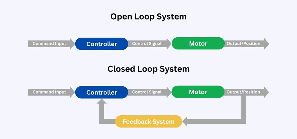
In contrast, closed-loop control uses sensors such as encoders or position sensors to monitor motor behavior in real-time. Feedback signals are processed by microcontrollers or PLC-based control systems to adjust voltage, current, or switching patterns. This enables accurate precision control, improved stability, and higher performance in applications such as servo motors, robotics, and industrial automation.
Pulse-Width Modulation (PWM)
In pulse-width modulation switching devices, such as MOSFETs, the power supply is rapidly turned on and off at high frequencies. By adjusting the duty cycle of the signal, the controller regulates the average voltage delivered to the electric motor.
PWM is highly efficient because the switching devices operate primarily in either the fully ON or fully OFF states, minimizing power loss. This method is widely used in DC motor, BLDC, and servo control applications where smooth, variable-speed operation and high energy efficiency are required.
Vector Control and Field-Oriented Control
Vector control, also known as field-oriented control (FOC), is an advanced control technique used in BLDC, servo motors, and AC motor systems. Unlike conventional methods, FOC independently controls magnetic flux and torque-producing current components within the motor.
The controller converts the three-phase currents into a rotating reference frame using mathematical transformations such as Clarke and Park transformations. This allows the motor controller to precisely regulate torque and flux components, resulting in improved dynamic response, reduced torque ripple, and enhanced motion-control performance in high-precision systems.
Voltage-to-Frequency (V/F) Control
For induction motors, a widely used control method is voltage-to-frequency (V/F) control. [4] In this strategy, the motor controller adjusts the supply voltage in proportion to the operating frequency to maintain a constant magnetic flux in the motor.
Maintaining a constant V/F ratio prevents magnetic saturation at low speeds and ensures sufficient torque at higher speeds. Because of its simplicity and reliability, V/F control is commonly used in industrial automation systems for applications such as pumps, conveyors, and fans, where precise control is not critical but stable variable-speed operation is required.
Recommended Reading: What Is a PWM Signal? Fundamentals and Practical Applications for Engineers
Design Considerations and Protection
Voltage, Current and Horsepower Ratings
The motor controller must be properly rated for the operating voltage, full-load current, and power capacity of the motor. These parameters determine whether the controller can safely supply the required electrical energy to the dc motor, ac motor, or brushless dc motor. Undersized controllers may overheat, experience component stress, or fail prematurely, while excessively oversized systems increase cost and reduce efficiency.
Designers must also consider the voltage class, whether the system operates in low-voltage environments or high-power industrial installations. Proper selection of switching components, such as MOSFETs or other solid-state power transistors, ensures reliable operation in both moderate- and high-power motion-control applications.
Protection Features
Overcurrent and Short-Circuit Protection - Fuses, circuit breakers or electronic current limits disconnect the supply when current exceeds safe limits.
Overtemperature Protection - Thermal sensors or algorithms monitor motor and drive temperature.
Under/Over-voltage Protection - Drives shut down or reduce current if supply voltage falls outside a safe range.
Inrush Current Limiting - Soft-starters or pre-charge circuits limit the high inrush current.
EMI Mitigation - Shielded cables, proper grounding and filtering minimize emissions.
Starting and Braking Methods
Motor startup and braking strategies significantly influence mechanical stress and energy consumption. For smaller electric motor systems, motor starters using direct-on-line (DOL) starting connect the motor directly to the power supply. However, this approach can produce large current surges.
Larger AC Motor and Induction Motors often use reduced-voltage starting techniques or soft starters to limit startup current. In advanced motor control systems, variable speed drives enable controlled acceleration and deceleration profiles.
Modern drives can also implement regenerative braking, where the motor operates as a generator during deceleration and returns electrical energy to the system. This capability improves energy efficiency in industrial automation and robotics applications.
Integration and Communication
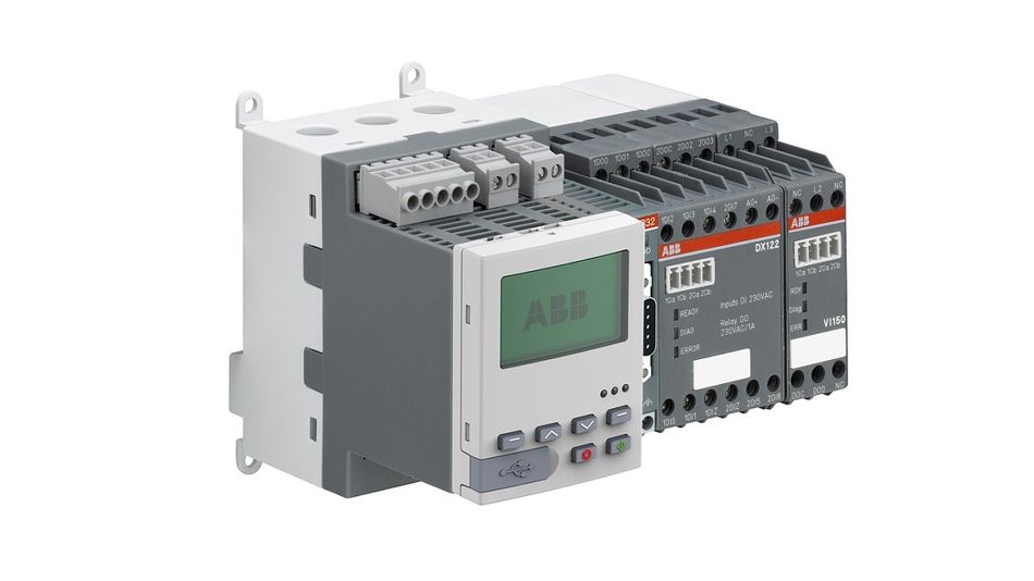
Modern motor controller designs increasingly incorporate communication interfaces that allow integration into complex industrial control systems. Embedded microcontrollers execute control algorithms and communicate with external devices, such as PLC systems or supervisory controllers.
The common communication interfaces include CAN, RS-485, Modbus, EtherCAT, USB, and other industrial networking protocols. These interfaces enable coordinated real-time motion control, monitoring, diagnostics, and remote configuration in large-scale automation systems.
Safety and Standards
Because motor control equipment operates in safety-critical environments, compliance with international electrical standards is essential. Standards such as IEC 61800 govern adjustable-speed drive systems, while regulations like NEC Article 430 define safe installation practices for motors and controllers in North America.
Selecting a Motor Controller
Selecting the right motor controller is essential for ensuring reliable motor control, efficient operation, and long service life of the electric motor. Engineers must evaluate several electrical, mechanical, and system-level parameters before choosing a controller. Let’s go through some parameters below:
Motor Type
Considerations: Identify the motor technology used in the system.
Typical Values / Notes: Brushed DC motor, brushless DC motor (BLDC), induction motors, servo motors, stepper motor controllers, or universal motors. The motor type determines the required motor control strategy.
Rated Voltage
Considerations: The motor controller must match the available power supply and motor voltage rating.
Typical Values / Notes: Common values include 12 V, 24 V, or 48 V DC and 230 V AC. Select controllers designed for the appropriate voltage range.
Full-Load Current
Considerations: Evaluate both continuous-current and peak (stall)- current capability.
Typical Values / Notes: The controller must handle short-term current spikes without overheating. Proper current limiting and overload protection are important.
Control Method
Considerations: Determine how the motor will be controlled.
Typical Values / Notes: The methods include analog voltage control, pulse-width modulation (PWM), or digital control through microcontrollers. High-performance systems may use FOC or advanced algorithms.
Feedback Requirements
Considerations: Determine whether feedback sensors are needed for accuracy.
Typical Values / Notes: Encoders, Hall sensors, or sensorless estimation methods are used in closed-loop systems for precise speed control and positioning.
Number of Axes
Considerations: Evaluate the number of motors in the system.
Typical Values / Notes: Controllers may support single-axis, dual-axis, or multi-axis motion control systems. Multi-axis drives simplify wiring and reduce system cost.
Braking and Reversing
Considerations: Assess braking requirements and direction control.
Typical Values / Notes: DC drives commonly use an H-bridge configuration, while advanced drives support regenerative or dynamic braking to improve energy efficiency.
Built-In Protection
Considerations: Protection features improve reliability and safety.
Typical Values / Notes: Look for overcurrent, overvoltage, thermal protection, reverse polarity protection, and fault diagnostics in the motor controller.
Communication Interface
Considerations: Integration with external control systems is often required.
Typical Values / Notes: Interfaces such as SPI, I²C, UART, RS-485, CAN, and Ethernet allow communication with PLC, Arduino, or other microcontrollers.
Operating Environment
Considerations: Environmental conditions affect controller durability.
Typical Values / Notes: Industrial controllers should support wide temperature ranges, vibration resistance, and humidity tolerance for harsh automation environments.
Recommended Reading: I2C vs SPI vs UART: A Comprehensive Comparison
Emerging Trends and Future Directions
Sensorless FOC and Adaptive Algorithms - Improved estimation techniques enable accurate rotor position and speed measurement without sensors.
Wide-Bandgap Devices - Silicon carbide (SiC) and gallium nitride (GaN) transistors operate at higher frequencies with lower switching losses.
Integrated Drivers and System-on-Chip - Integrated circuits combine gate drivers, MOSFETs, microcontrollers and communication interfaces into a single package.
Digital Connectivity and IoT - Ethernet-based protocols and wireless connectivity enable real-time monitoring and predictive maintenance.
Energy Recovery and Bidirectional Power Flow - Regenerative drives harvest braking energy and feed it back to the grid or battery.
Conclusion
Motor controllers are the brains and muscles of electric motor systems. They perform essential functions: starting, stopping, direction change, speed regulation, torque control and protection. Different motor types require tailored controllers: DC drives with PWM and H-bridge circuits, variable-frequency drives for AC motors, and servo and stepper controllers for precision positioning. Advanced control strategies like vector control and FOC deliver superior torque regulation and efficiency. With emerging technologies such as sensorless FOC, wide-bandgap devices, integrated drivers, and IoT connectivity, the future of motor control promises smarter, more efficient, and more integrated solutions.
Frequently Asked Questions (FAQs)
1. What is the difference between a motor controller and a motor driver?
A. A motor driver typically refers to the power stage that delivers current to the motor's windings, such as an H-bridge. A motor controller comprises the driver, control logic, protection circuits, and, often, a microcontroller.
2. How does a motor controller regulate speed?
A. For DC motors, speed is regulated by adjusting the average voltage or current delivered to the armature via PWM. For AC motors, variable-frequency drives synthesize AC at different frequencies and voltages.
3. Why is PWM preferred over variable resistance for speed control?
A. PWM turns the supply on and off rapidly, allowing the power transistors to operate efficiently in switching mode. This reduces heat dissipation and provides precise control. Using fixed resistors to reduce voltage wastes energy as heat, while PWM improves efficiency.
4. What is field-oriented control (FOC), and when is it used?
A. FOC is a vector control method that decomposes the stator current into direct (flux) and quadrature (torque) components. It provides smooth torque and high efficiency in permanent magnet synchronous and induction motors.
5. How do I choose between a stepper and a servo motor controller?
A. Steppers operate in open loop with discrete steps and are suitable for simple positioning. Servo motors use closed-loop feedback and maintain constant torque over a wide speed range. These systems are commonly used to drive mechanical actuators in automation equipment and precision machines.
6. Can a single controller operate multiple motors?
A. In some cases, one controller can drive multiple motors, but safety standards limit this. The NEC permits a single controller to operate multiple motors only when each motor is part of a single machine or is rated at 1/8 horsepower or less.
References
[1] Wikipedia. Motor Controller [Cited 2026 March 05]; Available at: Link
[2] IEEE. Review of BLDC Motor: State of Art, Advanced Control Techniques, and Applications [Cited 2026 March 05]; Available at: Link
[3] Toshiba. 120° Square-Wave Commutation for Brushless DC Motors [Cited 2026 March 05]; Available at: Link
[4] ResearchGate. Speed Control of Induction Motors Using V/f Control Method [Cited 2026 March 05]; Available at: Link
in this article
1. Key Takeaways2. Introduction3. Definition and Function of a Motor Controller4. Types of Motor Controllers5. Control Strategies6. Design Considerations and Protection7. Selecting a Motor Controller8. Emerging Trends and Future Directions9. Conclusion10. Frequently Asked Questions (FAQs)11. References