Understanding Silicon Controlled Rectifiers: Theory, Design and Practical Implementations
This article explores the working principles, circuit design techniques, and practical implementations of the silicon controlled rectifier, providing a comprehensive foundation for engineers and students in electronic system design.

07 Nov, 2025. 14 minutes read
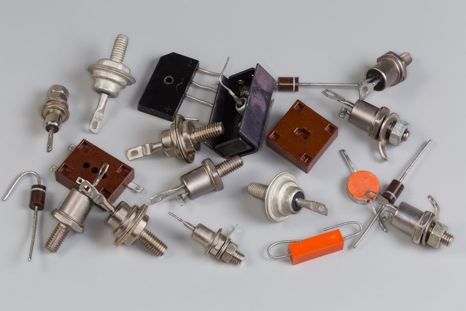
SCR (Silicon Controlled Rectifier)
Introduction
Silicon Controlled Rectifier (SCR) is a vital component in modern power electronics, offering precise control of high voltages and currents. It is a type of thyristor which operates as a unidirectional switch, handling large power levels efficiently. Since its introduction in the late 1950s, the silicon controlled rectifier has become indispensable in motor control, AC-DC conversion, and phase regulation. By combining the characteristics of both a diode and a transistor, it enables controlled conduction through gate-triggering mechanisms.
Engineers rely on the silicon controlled rectifier for its robustness, fast response, and compact design, which make it indispensable in automation and industrial circuits. This article explores the working principles, circuit design techniques, and practical implementations of the silicon controlled rectifier, providing a comprehensive foundation for engineers and students in electronic system design.
Fundamentals of Silicon Controlled Rectifiers
Origins and Evolution
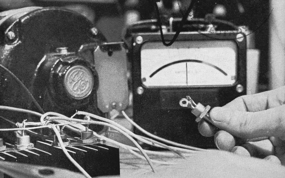
The Silicon Controlled Rectifier (SCR) originated at Bell Laboratories in the mid-1950s when a research team led by Gordon Hall conceptualized a controllable solid-state switch capable of handling high power. In 1956, the first practical SCR prototype was demonstrated, and by 1957, General Electric had commercialized the device, marking a major leap in power electronics. [1] The SCR revolutionized control systems by combining the rectifying behavior of a diode with the switching functionality of a transistor, making it ideal for AC power control and motor drives.
Early devices offered modest current and voltage capabilities, but subsequent advances in semiconductor processing, silicon wafer quality, and doping techniques increased ratings into the kilovolt and kiloampere ranges. Today, thyristors play critical roles in HVDC transmission systems, electric locomotives, inverters, and grid-scale converters, where high-power and high-voltage control is essential. The SCR remains one of the most robust and cost-effective switching devices in industrial and utility-scale applications.
Structure and Terminals
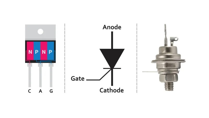
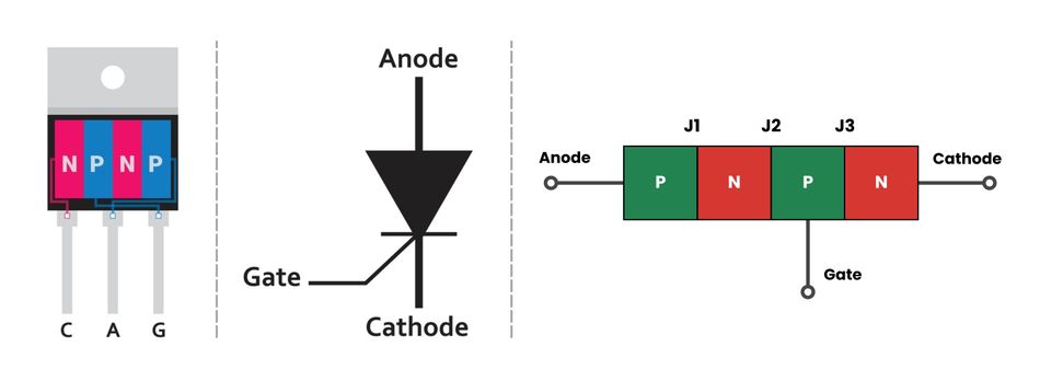
SCR consists of four layers of alternating p‑type and n‑type silicon arranged as P‑N‑P‑N. The figure below illustrates a simplified structure. The top p‑layer is connected to the anode while the bottom n‑layer forms the cathode. The inner p‑layer is lightly doped and includes the gate terminal.
The three junctions — J₁, J₂ and J₃ — exist between the layers. The doping profile is asymmetric: the outer layers are heavily doped to reduce series resistance, while the inner layers are lightly and moderately doped to set the blocking voltage and current gain. The gate contact is positioned close to junction J₂ so that injecting carriers there modulates the breakdown voltage of the central junction.
Although the SCR is often called a thyristor, the terminology varies in the literature. Thyristor refers to a family of four‑layer devices, whereas the silicon controlled rectifier is a specific member of that family. Some sources use the terms interchangeably, while others define the SCR as a subset of thyristors. Other variants include the TRIAC (bidirectional AC control), GTO (Gate Turn-Off thyristor), and RCT (Reverse Conducting Thyristor), each optimized for different power control applications. [2]
Two-Transistor Analogy and Latching Behavior
The internal operation of the SCR can be visualized using the two-transistor analogy, which simplifies the P-N-P-N structure into two coupled bipolar junction transistors — a PNP transistor (T₁) and an NPN transistor (T₂), connected in a regenerative feedback loop. Once a gate current triggers T₂, its collector current supplies base drive to T₁. In turn, the collector current in T₁ reinforces the base of T₂, creating positive feedback that rapidly drives both transistors into saturation.
Once the device enters the on state, conduction continues even after the gate signal is removed, as the internal loop sustains the anode current. The SCR remains latched until the anode current drops below a specific threshold known as the holding current. This self-sustaining behavior is fundamental to SCR operation and is why turn-off typically requires current interruption or commutation techniques in AC circuits.
Symbol and Polarity
The SCR symbol resembles that of a diode but includes an additional gate terminal near the cathode side. The arrow in the symbol indicates conventional current flow from anode to cathode, highlighting that the SCR is unidirectional; it conducts only when forward-biased and properly triggered.
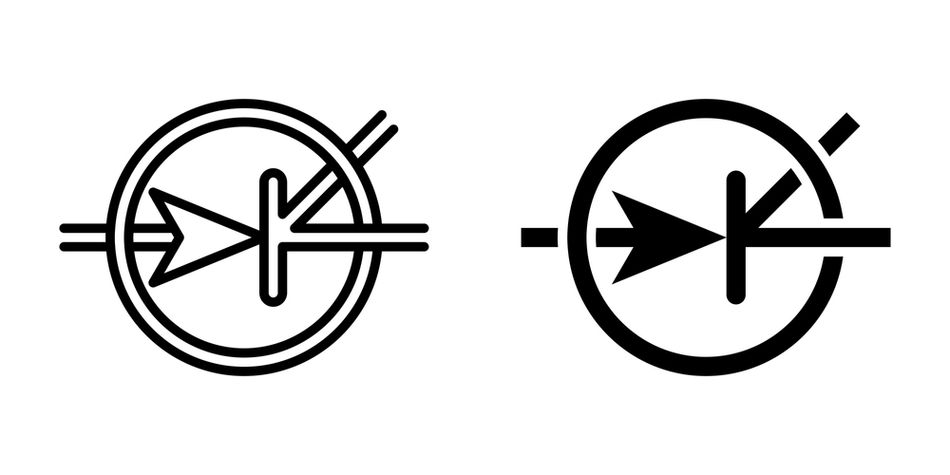
In the off state, even with a positive anode voltage, the device blocks current flow until a sufficient gate current or a breakover voltage is reached, initiating conduction. Unlike MOSFETs or TRIACs, which can conduct bidirectionally, the design of SCR makes it ideal for controlled rectification and DC conversion applications where unidirectional current and precise triggering are required.
Recommended Reading: Rectifier Diode: Revolutionizing Electrical Applications with Advanced Semiconductor Technology
Operating Principles
Modes of Operation
The Silicon Controlled Rectifier (SCR), a three-terminal thyristor, operates in three distinct modes depending on the biasing of its anode, cathode, and gate terminal. Each mode corresponds to a unique combination of junction biases (J₁, J₂, J₃) within the four-layer (PNPN) semiconductor structure.
Reverse-Blocking (Off) Mode: When the anode is negative relative to the cathode, junctions J₁ and J₃ are reverse biased, and the SCR behaves like two diodes in series; only a small leakage current flows.
Forward‑Blocking (Off) Mode: The anode is positive and the cathode is negative, but the gate is left open. Junctions J₁ and J₃ are forward biased while the middle junction J₂ remains reverse biased, resulting in high impedance and leakage current. The device stays off until the applied voltage reaches the break‑over voltage, at which point avalanche breakdown occurs at J₂.
Forward-Conduction (On) Mode: Once triggered, all three junctions conduct. The anode–cathode voltage drops to roughly 1–2 V, and the device behaves like a diode. The SCR remains in this state until the anode current falls below the holding current.
The positive feedback inherent in the two-transistor model explains why the SCR continues to conduct after the gate pulse is removed. The anode current must be reduced below the holding current by circuit means, through natural current zero crossing in AC systems or forced commutation in DC systems, to turn the device off.
Triggering Methods
Transitioning an SCR from the forward-blocking to forward-conduction state can be achieved through several triggering techniques, each exploiting different device parameters.
Gate Triggering: The most practical and widely used method applies a short positive pulse to the gate relative to the cathode. Injecting charge carriers into the p‑layer near junction J₂ lowers its breakdown voltage and initiates conduction. The magnitude of gate current determines the required anode voltage for turn‑on. Typical gate currents range from a few milliamps up to tens of milliamps, while gate trigger voltages vary from 0.6 V to a few volts depending on device size.
Forward Voltage (Breakover) Triggering: If the anode–cathode voltage rises to the break‑over voltage with the gate open, avalanche breakdown at J₂ triggers conduction. This method is hardly used because the resulting current surge can damage the SCR.
Rate-of-Rise (dv/dt) Triggering: The internal capacitances in SCR allow current to flow into the gate when the anode voltage changes rapidly. High dv/dt can unintentionally turn on the device; designers prevent this by adding a snubber circuit.
Thermal and Light Triggering: Increasing junction temperature reduces the break‑over voltage and can trigger the SCR, while light‑activated SCRs (LASCRs) use photons to inject carriers. These methods are used in specialised devices.
Turn‑Off Techniques (Commutation)
In AC applications, the SCR turns off automatically whenever the current crosses zero. In DC circuits, designers must force the anode current below the holding current. The common commutation techniques include:
Natural (Load) Commutation: In phase‑controlled AC circuits, the current naturally reverses direction at each half cycle. This automatically drives the anode current below the holding current, restoring the SCR to its forward-blocking state until the next firing angle command.
Resonant (Capacitor) Commutation: In this configuration, a charged capacitor is connected across the SCR through an inductive network. When triggered, the capacitor momentarily applies a reverse voltage across the device, forcing the anode current to zero. This method is common in DC choppers, inverters, and converter circuits where precise turn-off control is required.
Gate Turn-Off Thyristors (GTOs): In advanced thyristor designs such as GTOs, a negative gate current actively extracts carriers from the device, interrupting conduction. While standard SCRs cannot be turned off via the gate, GTOs and IGCTs extend thyristor technology into high-speed switching circuits and power electronics requiring dynamic control.
Recommended Reading: How Do MOSFETs Work: Comprehensive Technical Guide for Engineers (2025)
Electrical Characteristics and Parameters
I–V Characteristics
The forward I–V curve of an SCR exhibits two distinct regions: a high impedance forward blocking region up to the break‑over voltage, and a low‑impedance conduction region beyond it.
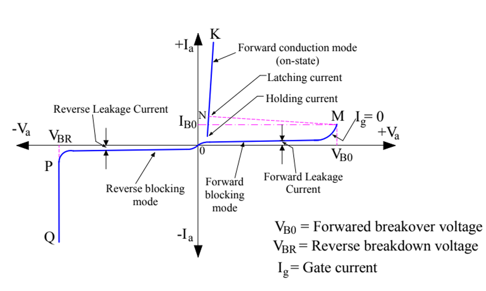
The break‑over voltage typically ranges from tens to hundreds of volts, depending on the device. When triggered into conduction, the anode–cathode voltage drops to around 1–2 V, largely independent of current. The reverse I–V characteristic resembles that of a diode until reverse breakdown occurs.
Latching Current and Holding Current
Two current thresholds define the turn-on and turn-off behavior of an SCR:
Latching Current: The minimum anode current required immediately after triggering to sustain conduction when the gate signal is removed. If the anode current does not exceed this value, the device may return to the blocking state. SCR stays latched provided its current stays above the latching current.
Holding Current: The minimum anode current required to keep the SCR in the conducting state once it has latched. Dropping below this current causes the SCR to switch off. Because latching current is measured during turn‑on and holding current during steady conduction, latching current is usually higher than holding current.
Typical small‑signal SCRs have latching currents of 5–20 mA and holding currents of 2–10 mA. Power SCRs designed for tens or hundreds of amperes can have latching currents of 50–150 mA and holding currents of 20–100 mA, as specified by manufacturers in their datasheets. [3]
Gate Characteristics
The gate–cathode junction behaves as a forward-biased diode, with a typical voltage drop ranging from 0.6 V to 3 V. The gate trigger current, the current required to switch the SCR from the forward-blocking to forward-conduction state, ranges from 2 mA for small devices up to 150 mA for high-power thyristors.
The brief gate pulse of a few milliamperes can control anode currents of several tens or hundreds of amperes, demonstrating the exceptional current amplification in SCR. However, excessive gate current or prolonged drive can overheat the gate junction, so designers use resistor–capacitor (RC) shaping networks or opto-isolated drivers to ensure safe triggering. Both gate trigger current and gate trigger voltage decrease with rising temperature due to enhanced carrier mobility and junction conductivity.
Design Considerations and Protective Measures
Snubber Circuits for dv/dt Protection
The Silicon Controlled Rectifier (SCR) possesses inherent junction capacitances, particularly between the anode and gate. A rapid increase in anode voltage (high dv/dt) can cause displacement current to flow through this capacitance, inadvertently injecting charge into the gate terminal and triggering the device unintentionally.
To suppress such false triggering, designers employ RC Snubber Networks, a resistor (R) and a capacitor (C) connected in series across the SCR. When the supply voltage changes abruptly, the capacitor initially behaves as a short circuit, limiting the rate of voltage rise (dv/dt) across the device. As it charges through the series resistor, the voltage across the SCR builds gradually, keeping dv/dt within a safe operating limit.
Once the SCR switches on, the charged snubber capacitor discharges through the device. The resistor in the snubber limits both discharge current and di/dt, thereby preventing voltage spikes and improving device reliability.
di/dt Limiting and Series Inductance
Excessive rate of rise of current (di/dt) during turn-on can cause localized current crowding near the cathode junction, producing hot spots before charge carriers spread uniformly. If the anode current increases too rapidly, thermal stress may exceed the silicon’s safe operating limits, leading to permanent damage.
To control di/dt, a series inductor (often called a commutation or surge-limiting reactor) is placed in line with the SCR. This inductor momentarily resists changes in current, ensuring a uniform current distribution across the P-N-P-N structure.
The typical inductances are:
Low-Power SCRs: 1–10 µH
High-Power Thyristor Modules: 10–100 µH
These inductors effectively shape current rise during turn-on without introducing significant power loss.
Over-Voltage and Over-Current Protection
SCRs must be safeguarded against both internal and external over-voltage conditions:
Internal Over-Voltage: Occurs when reverse recovery current decays abruptly, inducing high L x (di/dt) voltage spikes across the device due to circuit inductance.
External Over-Voltage: Results from transient events such as lightning strikes, switching surges, or line faults.
Protection is achieved using:
Metal-Oxide Varistors (MOVs) or Transient Voltage Suppressors (TVSs) placed across the SCR to clamp voltage spikes and absorb surge energy.
Fast-acting Fuses and Magnetic Circuit Breakers to limit fault currents and prevent thermal runaway.
Gate Protection Circuits using zener diodes and series resistors to ensure gate voltage and gate current remain within rated limits.
Effective over-voltage and over-current protection is essential for maintaining long-term device reliability in industrial power control systems.
Thermal Management and Mounting
The on‑state voltage drop of an SCR may seem small, but at high currents it dissipates significant power. Without proper thermal control, the junction temperature can exceed its limit, typically ranging from 125 °C to 150 °C, leading to thermal runaway or junction failure. [4]
To maintain thermal stability, SCRs employ heat sinks, forced-air cooling, or liquid-cooled cold plates, depending on power rating. Thermal resistance must be minimized to ensure effective heat transfer from the junction to the ambient.
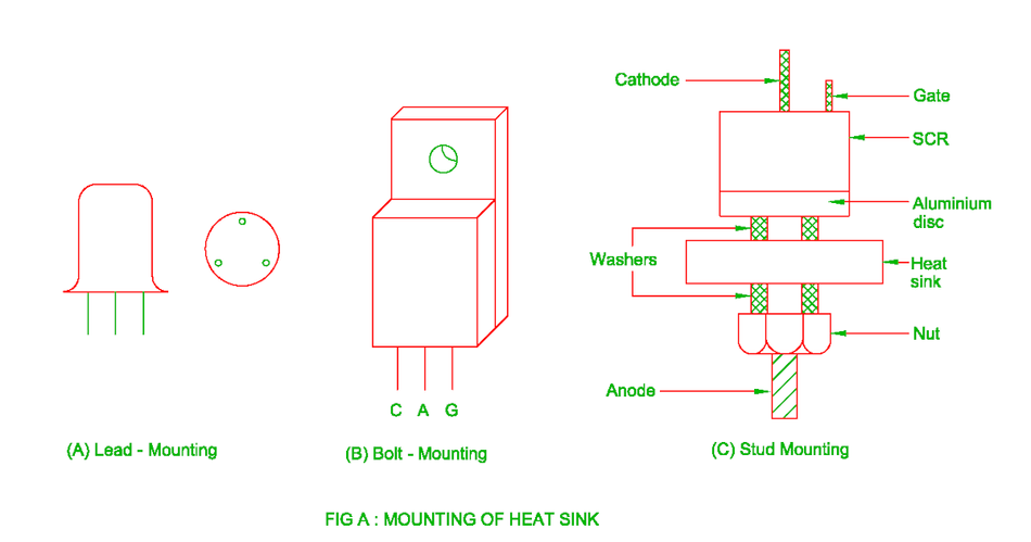
Mounting configurations vary with power class:
Lead-mounted SCRs for low-current, PCB-level circuits
Stud or bolt-down packages for medium-power industrial drives
Press-pack thyristors for high-voltage, high-current converters, and HVDC transmission
Proper torque during mounting, use of thermal interface materials (TIMs), and secure mechanical contact are critical for consistent thermal performance and electrical isolation.
Gate Drive Circuit Design
Reliable gate triggering is vital for consistent SCR operation. The gate drive circuit must supply a short-duration current pulse sufficient to exceed the gate trigger current, while ensuring that the gate–cathode voltage does not surpass the rated, maximum gate voltage.
RC Triggering Circuits: Widely used in AC phase control, where a resistor–capacitor (RC) network charges each half-cycle to a variable phase angle, then discharges through a pulse transformer into the gate. Adjusting the RC time constant controls the firing angle (0°–180°) for power regulation.
Unijunction Transistor (UJT) Triggering: Provides sharp, repeatable pulses for industrial power controllers and rectifiers, ensuring precise synchronization with the AC waveform.
Digital and Opto-Isolated Gate Drivers: In modern systems, microcontrollers, DSPs, or opto-isolators generate clean, noise-immune pulses that safely interface low-voltage control circuits with high-voltage power stages.
A low-impedance gate source is preferred to achieve a high di/dt of gate current, reducing turn-on delay and improving noise immunity. Proper gate drive design ensures stable triggering, minimizes false firing, and extends the operational lifetime of the SCR.
Recommended Reading: Zener Diode: A Comprehensive Guide to Its Principles and Applications
Practical Implementations and Circuit Examples
Basic DC Switch
A Silicon Controlled Rectifier (SCR) can function as a simple electronic DC switch. The anode connects to the positive supply through a load, and the cathode connects to ground. With no gate current, the SCR remains in its forward-blocking mode, behaving like an open switch and allowing only leakage current to flow.
When a gate pulse or pushbutton trigger is applied, junction J₂ becomes forward biased, initiating conduction between anode and cathode. Once latched, the SCR maintains conduction even after the gate signal is removed, as long as anode current exceeds the holding current. The device returns to its off state only when the supply voltage is removed or the load current falls below the holding current.
This configuration demonstrates the latching capability of an SCR, making it a reliable solid-state replacement for mechanical relays in DC switching and control systems.
AC Phase Control (Light Dimmers and Heater Controllers)
In AC circuits, the SCR benefits from natural commutation at each zero crossing, enabling precise phase control of load power. By varying the gate triggering angle (α) relative to the start of each half cycle, engineers control the conduction angle, thereby adjusting the average voltage delivered to the load.
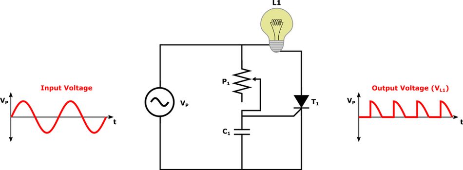
This principle underpins lamp dimmers, temperature controllers, and industrial welding regulators, where proportional control of AC power is required.
Half-Wave Control: One SCR with a diode in antiparallel conducts for alternate half-cycles, suitable for low-cost light dimmers.
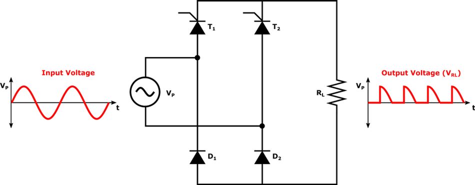
Full-Wave Control: Two SCRs connected back-to-back conduct alternately, ensuring symmetrical current flow through resistive or inductive loads.
Modern TRIACs, a bidirectional variant of the thyristor, combine the function of two SCRs in a single device but exhibit higher leakage currents and reduced dv/dt ratings at elevated temperatures. Despite this, SCR-based phase controllers remain preferred in high-power heating and industrial automation applications for their durability and efficiency.
Crowbar Over-Voltage Protection
The crowbar circuit is a classic application of the SCR for over-voltage protection in sensitive electronic systems. When the supply voltage exceeds a predetermined threshold, a zener diode or voltage-sensing network delivers a trigger pulse to the gate terminal of the SCR.
Once triggered, the SCR transitions to its on state, providing a low-impedance path between the supply and ground. This action rapidly discharges the supply and causes the series fuse or circuit breaker to blow, isolating the protected load. Because the SCR remains latched until the anode current falls below the holding current, the protection remains active even after the over-voltage event ends.
In high-energy applications, reverse-conducting thyristors (RCTs) integrate an antiparallel diode, simplifying crowbar circuit design by allowing both forward conduction and reverse current handling. This combination ensures fast response, high reliability, and low cost, making SCR-based crowbar protection indispensable in power supplies, telecommunication systems, and industrial controllers.
Motor Control and HVDC Converters
SCR bridge converters form the backbone of modern motor control and high-voltage direct current (HVDC) transmission systems. In DC motor drives, SCRs are configured in three-phase full-wave bridges, where six thyristors conduct sequentially according to the firing angle (α). By varying α between 0° and 180°, engineers regulate the output DC voltage, allowing precise speed control and torque regulation for heavy industrial machinery such as steel mills, paper plants, and mining conveyors.
For improved efficiency and power quality, 12-pulse and 24-pulse converter systems employ multiple SCR bridges phase-shifted by transformer windings to reduce harmonic distortion and enhance power factor. [5]
In HVDC transmission, thousands of series-connected SCR valves operate in perfect synchronization to convert AC to DC (rectification) or DC back to AC (inversion). These systems handle megawatt-level power with exceptionally high reliability, leveraging the SCR’s high-voltage, high-current, and thermal endurance characteristics. Such converters represent the best of power control applications, where silicon controlled rectifiers continue to dominate due to their proven efficiency, robustness, and cost-effectiveness.
Advantages, Limitations, and Device Comparisons
Advantages
Silicon Controlled Rectifiers (SCRs) offer several compelling advantages that make them useful in high-power control systems:
High Power Handling: Owing to their PNPN thyristor structure, SCRs can regulate currents ranging from a few amperes to several thousand amperes and block voltages in the kilovolt range. This makes them ideal for heavy-duty industrial drives, HVDC converters, and power control applications.
Low On-State Loss: In the forward conduction mode, the voltage drop is typically only 1–2 V, resulting in minimal conduction losses and high overall power efficiency.
Simple Gate Drive Requirements: Only a brief trigger pulse of gate current is necessary to switch the device on. No continuous gate power is required to maintain conduction, simplifying circuit design and improving energy efficiency.
Mechanical Robustness and Cost Efficiency: SCRs are available in rugged stud, bolt-down, and press-pack packages. Their mature manufacturing process ensures low cost per kilowatt handled and excellent surge current capability, allowing safe operation during transient overloads.
Limitations
Despite their numerous strengths, SCRs present several design and operational limitations:
Unidirectional Conduction: Standard SCRs conduct current only from anode to cathode and cannot handle reverse current flow. Circuits requiring bidirectional control must use anti-parallel diodes or TRIACs for reverse current paths.
Slow Turn-Off and Low Switching Frequency: The internal latching mechanism limits turn-off speed. Typical maximum operating frequencies remain below 1–2 kHz, making SCRs unsuitable for high-frequency switching converters or pulse-width modulation (PWM) control.
dv/dt and di/dt Sensitivity: Rapid changes in voltage or current can induce false triggering or localized hot spots, requiring RC snubber networks and series inductors for safe operation and enhanced device longevity.
Need for Commutation Circuits: In DC circuits, SCRs cannot turn off naturally. They require forced commutation networks, which add design complexity. Although Gate Turn-Off Thyristors (GTOs) address this, they come with higher cost and control requirements.
Comparison with Other Power Switches
In modern power electronics, SCRs coexist with MOSFETs, IGBTs, and TRIACs, each serving distinct performance niches:
SCRs: Excel in high-power, low-frequency systems where efficiency, robustness, and surge capability are paramount. Typical applications include motor drives, AC regulators, HVDC converters, and crowbar protection circuits.
MOSFETs (Metal-Oxide-Semiconductor Field-Effect Transistors): Offer fast switching and high input impedance, making them ideal for high-frequency, low- to medium-power converters, inverters, and DC–DC power supplies. However, MOSFETs have higher on-state resistance and lower voltage ratings compared to SCRs.
IGBTs (Insulated Gate Bipolar Transistors): Combine the high input impedance of MOSFETs with the high-current capability of bipolar transistors. They provide an effective balance for medium- to high-power, medium-frequency switching applications such as industrial drives and renewable energy converters, though they are more expensive and thermally sensitive.
TRIACs: Essentially integrate two SCRs in inverse parallel for bidirectional AC control, simplifying dimmer and heater controller circuits. However, TRIACs exhibit higher leakage currents, lower surge ratings, and less dv/dt immunity than dedicated SCRs, restricting them to moderate power levels.
SCRs dominate high-voltage, high-current, low-frequency environments where efficiency, simplicity, and ruggedness outweigh the need for rapid switching. Their continued evolution, alongside GTO, IGCT, and hybrid thyristor technologies, ensures their relevance in the next generation of power control and smart grid applications.
Recommended Reading: Types of Switches: Complete Engineering Guide for 2025
Conclusion and Future Outlook
The silicon controlled rectifier is a foundational device in power electronics. Its four-layer structure and regenerative feedback enable high-power switching with a simple gate drive. Engineers use SCRs in AC phase control, DC drives, HVDC converters and protection circuits, benefiting from their robustness and low conduction loss. However, the device’s unidirectional conduction, relatively slow turn‑off and sensitivity to dv/dt and di/dt require careful circuit design with snubber networks, inductive smoothing and commutation schemes.
Looking ahead, SCRs continue to evolve! Silicon‑carbide (SiC) thyristors offer higher voltage ratings and lower switching losses, while integrated gate‑commutated thyristors (IGCTs) and gate turn‑off thyristors provide improved controllability. Nevertheless, the classical SCR remains indispensable wherever rugged, cost‑effective control of high power is required. By understanding its theory and practical considerations, engineers can leverage this mature technology in modern systems alongside fast‑switching MOSFETs and IGBTs.
Frequently Asked Questions (FAQ)
1. What is the difference between a silicon controlled rectifier (SCR) and a generic thyristor?
A. A thyristor refers to a family of four-layer PNPN devices with latching behavior. The Silicon Controlled Rectifier (SCR) is a specific unidirectional type that blocks reverse current and conducts under positive voltage via its anode terminal.
2. How do latching current and holding current differ?
A. The latching current is the minimum anode current required immediately after triggering to sustain conduction when the gate pulse is removed. The holding current is the lower threshold below which the SCR turns off once it has already latched.
3. Why is an RC snubber necessary across an SCR?
A. The internal pn junctions in SCR, particularly near junction J2, exhibit capacitance between the anode and cathode terminals. A snubber circuit (resistor–capacitor) limits dv/dt, prevents false turn-on, and protects against reverse breakdown voltage transients.
4. Can an SCR conduct current in both directions?
A. No. A standard SCR conducts current only from anode terminal to cathode terminals under positive voltage. For bidirectional AC power supplies, designers use two SCRs in parallel or a TRIAC structure.
5. How is an SCR turned off in a DC circuit?
A. In DC power supplies, an SCR stays on until the anode current drops below the holding current. Designers use commutation circuits or apply a negative voltage to restore the reverse blocking mode.
6. When should I choose an SCR over a MOSFET or IGBT?
A. Select an SCR when the application involves high power, low switching frequency (line frequency or a few kilohertz), unidirectional conduction and when simple, cost‑effective gate drive and ruggedness are priorities. For high-frequency or bidirectional control, MOSFETs, IGBTs, or TRIACs are more suitable.
References
[1] ResearchGate. SCR Is 50 Years Old [History] [Cited 2025 November 06] Available at: Link
[2] IDC. Thyristors and Triacs [Cited 2025 November 06] Available at: Link
[3] DigiKey. Rectifier/Thyristor Modules Applications [Cited 2025 November 06] Available at: Link
[4] STMicroelectronics. How to select the right thyristor (SCR) [Cited 2025 November 06] Available at: Link
[5] TORONTOMU. Multi-pulse SCR Rectifiers [Cited 2025 November 06] Available at: Link
in this article
1. Introduction2. Fundamentals of Silicon Controlled Rectifiers3. Operating Principles4. Electrical Characteristics and Parameters5. Design Considerations and Protective Measures6. Practical Implementations and Circuit Examples7. Advantages, Limitations, and Device Comparisons8. Conclusion and Future Outlook9. Frequently Asked Questions (FAQ)10. References