Types of Circuits: A Comprehensive Guide for Engineering Professionals
This guide offers an in-depth overview of different types of electric circuits, exploring their foundational concepts, common circuit layouts, specialized circuits, the latest technological advances, and their applications in real-life scenarios.

13 May, 2024. 14 minutes read

Diagram of an open circuit with circuit components
Introduction
Electrical circuits are the fundamental building blocks of modern electronic systems. The appropriate use of different types of circuits—open, closed, or short circuits—and the proper selection of series, parallel, or series-parallel circuits profoundly impact the functionality, safety, and efficiency of electrical systems. The choice of the type of circuit significantly influences voltage and current regulation, which is crucial for the reliable operation of any electronic system.
In real-world applications, distinguishing between alternating current (AC) circuits and direct current (DC) circuits is crucial for projects ranging from simple household appliances to complex power distribution systems. Engineers must decide the most suitable type of circuit to ensure optimal energy conversion and efficiency. Similarly, understanding the differences between single-phase circuits and polyphase circuits is critical in industries where power output and distribution efficiency are a priority, such as in manufacturing facilities or power plants.
Moreover, this knowledge is not just about selecting the right type of circuit; it's about innovating and pushing the boundaries of what's possible with modern technology. Let’s explore the fundamental circuit concepts and understand the crucial role of circuitry in the advancing engineering landscape.
Exploring the Fundamentals: Core Circuit Concepts
Understanding Circuit Classification
Circuits are the interconnected pathways that enable electrical current to flow and perform various functions. Circuit classification categorizes circuits based on their properties and functionalities, providing a systematic approach to comprehension.
In electrical engineering, circuits are classified as open, closed, or short, which is crucial for designing robust and efficient systems. Each type of circuit plays a key role in the overall behavior of electrical systems, impacting their functionality, safety, and reliability.
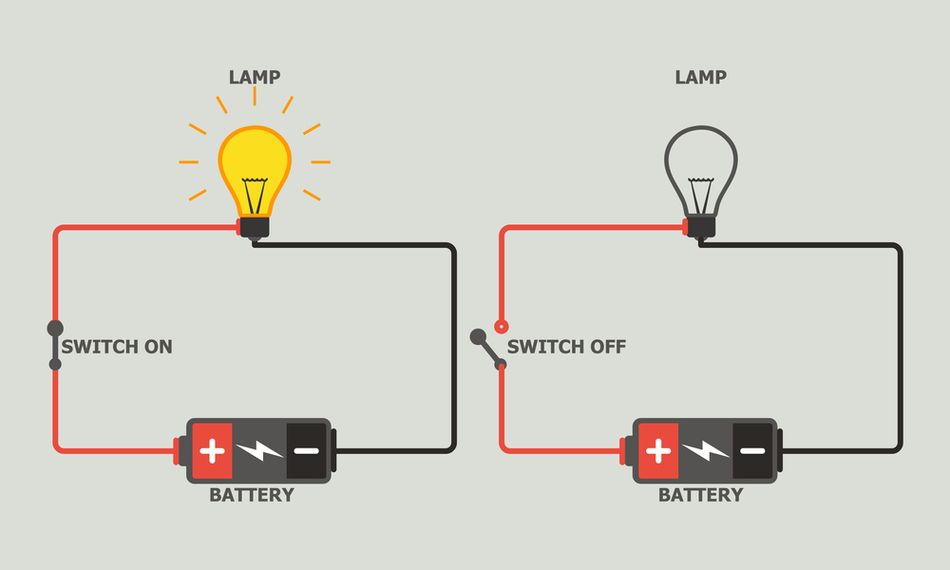
Open Circuits:
An open circuit refers to a condition where the current flow is interrupted. This happens due to a break or discontinuity in the otherwise closed loop that allows current to circulate. It's essentially like having a gap in a pipe carrying water - no flow can occur. [1]
In sensor technologies, open circuits detect system breaks or disconnections, triggering alarms or shutdown mechanisms. They are characterized by no current flow due to a break or gap, theoretically leading to infinite resistance. The voltage across an open circuit can be significant, while I (Current) = 0 A, making R (Resistance) approach infinity, in Ohm’s Law:

Open circuits are typically avoided in power circuits but are essential in control and safety circuits where detecting a break or disconnection is required. These circuits can be intentional, like a light switch turned off, or unintentional, due to loose connections, broken wires, or faulty electrical components.
Understanding open circuits is crucial for troubleshooting electrical systems. When a device isn't functioning, an open circuit could be the culprit. By identifying and fixing the break in the circuit, you can restore proper current flow and get your device working again.
Closed Circuits:
Conversely to an open circuit, a closed circuit is the ideal state for electrical current to flow. It signifies a complete, uninterrupted path that allows electricity to travel freely from the source (like a battery) to the load (like a light bulb) and back. Imagine a closed loop pipe with circulating water - that's analogous to a closed circuit with flowing current.
Most household and industrial electrical systems are designed as closed circuits to ensure continuous power supply. In closed circuits, current can flow freely with resistance dependent on the elements within the circuit, influencing both power consumption and energy distribution efficiency.
A closed circuit typically involves a power source, conducting wires, and a load. A switch can be present to control the flow by creating or breaking the circuit (turning it on or off). Ohm's Law:

is pivotal in calculating the operational parameters of a closed circuit.
In designing electrical layouts, closed circuits are optimized for minimal resistance to enhance efficiency but safeguarded by circuit breakers to prevent overload.
Short Circuits:
A short circuit occurs when a low-resistance pathway bypasses a significant part of a circuit, allowing a high flow of current. Short circuits are common in electrical accidents and can lead to significant damage and safety hazards.

A short circuit creates a low-resistance connection between points in the circuit that shouldn't be directly connected. This could be due to exposed wires touching, damaged insulation, or internal component failure. Short circuit is marked by dangerously high current flows due to minimal resistance, often resulting in overheating and potential fires.
Electricity naturally seeks the path of least resistance. Electric Power Equation:

highlights the potential for high power dissipation, explaining why short circuits can generate excessive heat and damage. Short circuits require immediate attention in system designs, including protective measures like fuses and circuit breakers that can detect and interrupt an excessive amount of current.
By understanding these classifications, engineers can better predict and design against potential issues, ensuring that systems are effective and safe. Knowing where and how each type of circuit is used can guide decisions from system design to troubleshooting, underlining the importance of circuit classification in electrical engineering.
In-Depth Look at Series and Parallel Circuits
Circuits come in various configurations, each with its own unique electrical behavior. Two fundamental classifications are series and parallel circuits. These configurations determine how components are assembled and influence the overall behavior of circuits, affecting everything from power distribution to device functionality.
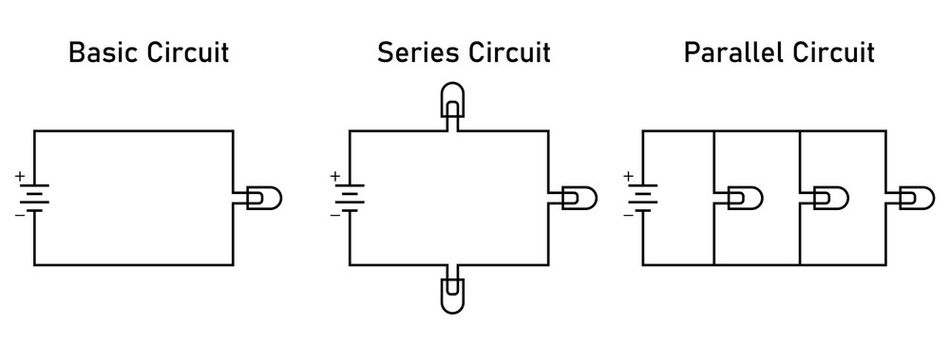
Series Circuits:
In series circuits, components are connected end-to-end, creating a single path for current flow. Let’s take a string of lights as an example: if one bulb burns out, the entire string goes dark. That's because, in a series circuit, all the components are like links in a chain – interrupting the flow at any point disrupts the entire circuit.
The sum of the individual resistances along the circuit determines the equivalent resistance, calculated by:

This configuration ensures that the same current flows through each component, but the voltage drop across each varies, dictated by Ohm's Law.
By arranging resistors in series, we can create a voltage divider circuit. This allows us to obtain a specific voltage output from a higher supply voltage. Understanding series circuits is fundamental for electronics and electrical work. Knowing how current and voltage behave in these circuits allows us to design and analyze them for various applications.
Parallel Circuits:
In contrast to series circuits, a parallel circuit offers multiple pathways for current to flow. Let’s take the example of a group of friends walking from a meeting point. Each takes a different route to explore a park, but all end up at a designated picnic spot later.
Similarly, components in a parallel circuit are connected across the same two voltage points, allowing the current to choose its path based on resistance. This arrangement allows the voltage across each branch to remain constant, but the current divides among the branches, inversely proportional to the resistance of each branch.
The total resistance of the circuit is less than the smallest of the individual resistances, given by:

Parallel circuits are essential in residential and commercial building wiring, where appliances may require the same voltage but varying currents. A key advantage of parallel circuits is that if one branch experiences a failure (open circuit), the other branches continue to function normally.
Resistors can be connected in parallel to achieve a lower overall resistance than any individual resistor. Household electrical wiring is a prime example of a parallel circuit. Lights, appliances, and outlets are all connected in parallel across the same voltage source. Turning off one light doesn't affect the others because each has its own independent path for current flow.
Understanding parallel connections is essential for working with electrical systems. They offer flexibility and redundancy, making them crucial for powering various electrical devices and ensuring independent operation within a larger system.
Kirchhoff’s Laws
Kirchhoff's Current Law (KCL) and Kirchhoff's Voltage Law (KVL) are pivotal in analyzing these circuits. KCL states that the total current entering a junction equals the total current leaving it, which is instrumental in parallel circuit analysis. KVL, stating that the sum of the electrical potential differences around any closed circuit loop must be zero, is crucial for series circuits.

The laws, formulated by Gustav Kirchhoff in 1845, are based on the conservation of electric charge and energy. These foundational principles in physics ensure the predictability and stability of electrical circuits. [2]
Kirchhoff's Laws allow us to calculate unknown currents and voltages in complex circuits by forming a system of equations. By applying these laws, we can identify faults or malfunctions in circuits by analyzing current and voltage imbalances. This also enables engineers to design circuits with desired characteristics.
Engineers and designers can ensure the operational efficiency and safety of their electronic devices and circuits by following these laws and configurations.
Recommended Reading: What is an Open Circuit: A Deep Dive for Engineers
Innovations in Circuit Design and Application
Special Circuits: AC and DC, Single-Phase and Polyphase
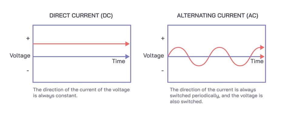
The distinction between Alternating Current (AC) and Direct Current (DC) circuits is foundational in the field of electrical engineering, shaping everything from household electronics to national power grids. AC circuits, characterized by their oscillating current, enable efficient long-distance power transmission, a breakthrough defining modern electricity distribution. Conversely, DC circuits provide a constant current flow, which is ideal for electronic devices and batteries, underscoring their importance in consumer electronics.
The historic battle for dominance between AC and DC power in the late 1880s is often called the "War of Currents." [3] This led to the widespread adoption of AC due to its efficiency over long distances, championed by Nikola Tesla and George Westinghouse. In modern contexts, DC is experiencing a comeback in applications like solar power systems and electric vehicles, highlighting its importance in renewable energy technologies.
Phase Relationships and Power Factor in AC Circuits:
AC systems can operate at single-phase or polyphase (typically three-phase), with polyphase systems being more efficient for transmitting electricity over vast networks without substantial power losses. The power factor in AC circuits—a measure of power efficiency—is crucial in designing systems that maximize the actual useful power output versus the total power transmitted.
Transformers and Voltage Transformation:
Transformers are pivotal in polyphase AC systems, allowing for voltage adjustments necessary for efficient power transmission and distribution. Innovations in transformer design have significantly enhanced grid reliability and performance, facilitating the integration of renewable energy sources into the grid.
Comparative Analysis: Single-Phase vs. Polyphase Circuits:
Single-phase power is sufficient for residential use where lower power loads are typical, whereas polyphase power is essential in industrial settings where high power loads are common. Technological advancements have optimized polyphase systems for better performance and reliability, particularly in heavy industries and large-scale renewable installations.
| Characteristic | Single-Phase Circuit | Three-Phase or Polyphase Circuit |
| Wires | 2 (Live and Neutral) | 3 or 4 (3 Phases + Neutral [Optional]) |
| Current Flow | AC current alternates between positive and negative in a single path | AC current alternates in three separate phases, creating a more constant flow |
| Voltage | Delivers one AC voltage level | Delivers three AC voltage levels, each phase-shifted by 120 degrees |
| Power Delivery | Lower power capacity, suitable for residential and light commercial applications | Higher power capacity, efficient for industrial applications and high-power motors |
| Complexity | Simpler design and easier to understand | More complex design requiring knowledge of three-phase power relationships |
| Efficiency | Less efficient due to fluctuations in power delivery | More efficient due to more constant power transfer |
| Cost | Generally lower installation and maintenance costs | Higher installation and maintenance costs due to additional conductors and potentially control systems |
The development and optimization of AC and DC circuits, along with single-phase and polyphase systems, continue to drive innovations in power distribution and electronic device manufacturing, reflecting their critical role in major historical and contemporary engineering challenges.
Recommended Reading: Contactor vs Relay: Understanding the Differences and Applications
Recent Technological Advances in Circuit Engineering
In the rapidly evolving field of circuit engineering, introducing innovative materials such as graphene and silicon carbide represents a significant leap forward. These materials are not only improvements over existing technologies but game-changers that redefine what is possible in electronics design.
Graphene:
Graphene, often called a 'wonder material,' is a single layer of carbon atoms arranged in a two-dimensional honeycomb lattice. [4] It exhibits extraordinary electrical, thermal, and mechanical properties, making it ideal for various applications in electronics and beyond.
In circuit design, graphene's superior electrical conductivity and exceptional heat dissipation capabilities enable the creation of faster and more robust devices that manage thermal loads. This makes graphene integral in developing devices like ultra-fast transistors, flexible displays, and advanced sensors that require high performance in compact forms.
Silicon Carbide:
Silicon carbide stands out for its ability to maintain structural integrity at high temperatures, surpassing traditional materials like silicon in high-power, high-frequency applications. This robustness makes it valuable in harsh environments such as automotive and aerospace electronics, where reliability and efficiency are paramount. For example, its implementation in electric vehicle power systems helps manage high voltage operations more effectively, significantly enhancing battery life and performance.

Recent advancements underscore the transformative impact of these materials. A notable example includes the development of silicon carbide-based semiconductors in renewable energy applications, particularly in solar power inverters. They improve efficiency and durability, reducing overall energy waste. Similarly, research into graphene-enhanced composite materials for wind turbines has demonstrated their potential to reduce weight while increasing the strength and longevity of turbine blades.
The integration of graphene and silicon carbide into modern circuit designs is not just an enhancement of existing frameworks but a redefinition of the boundaries of technology. These materials enable the development of more efficient, durable, and compact devices, paving the way for future innovations that could transform everyday technology.
Recommended Reading: PCB Material: A Comprehensive Guide to Understanding and Choosing the Right Materials
Real-World Applications of Advanced Circuit Configurations
Advanced circuit configurations are revolutionizing various industries, solving complex engineering challenges, and significantly enhancing system reliability and efficiency. The evolution of circuit technologies has paved the way for transformative changes in sectors such as renewable energy, automotive electronics, and smart grids.
Renewable Energy Systems
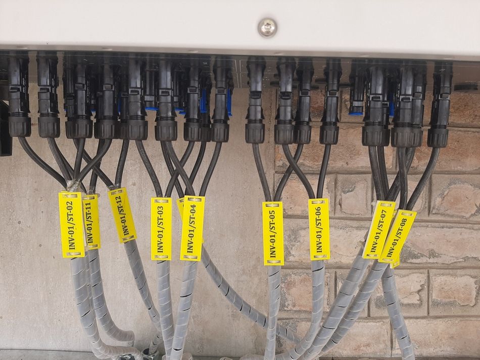
The advent of advanced circuitry in solar energy systems has revolutionized how power is managed from unpredictable sources. Solar inverters today use sophisticated circuits to handle the variable input from solar panels efficiently. They ensure a consistent power supply regardless of fluctuations in solar intensity.
Historically, solar energy conversion faced challenges due to its dependency on weather conditions. Advanced circuits have mitigated these issues by enabling dynamic responses to changing solar outputs. Modern solar inverters incorporate Maximum Power Point Tracking (MPPT) and advanced voltage regulation to maximize energy extraction and conversion efficiency.
Studies show that these advancements have led to a 28.5% increase in energy utilization efficiency, contributing to the broader adoption of solar power. [5]
Automotive Electronics
In automotive electronics, particularly in electric vehicles (EVs), advanced circuits are crucial for managing high-energy batteries and drive systems efficiently and safely.
With the evergrowing demand for EVs, there is a need for more efficient power management systems. Advanced circuits have been pivotal in meeting these demands by enhancing battery life and vehicle performance. Battery Management Systems (BMS) use complex algorithms to balance cell charge and manage power distribution, extending battery life and vehicle range.
Innovations in circuit design have improved battery efficiency by up to 40%, making EVs more viable for the mass market. [6]
Smart Grid Technology
Smart grids represent a significant leap in electricity distribution. They use advanced circuit configurations to manage loads, predict demand, and seamlessly integrate renewable sources.
The transition to smart grids was driven by the need for more resilient and efficient power systems integrating various energy sources. Advanced circuits in smart grids optimize power flow, reduce transmission losses, and enhance grid stability through real-time monitoring and automated management.
Implementations of these technologies have reduced energy waste by 25% in urban areas, showcasing the critical role of advanced circuits in modern energy infrastructure. [7]
These examples underscore the critical role of advanced circuit configurations in driving technological progress across sectors, enabling a shift towards more sustainable and high-performing systems.
Recommended Reading: Energy Storage System (ESS) Technologies Most Suitable for Renewable Energy Usage
Navigating Challenges in Circuit Implementation
Implementing circuits effectively in various applications involves overcoming several technical and practical challenges that have historically shaped the field of circuit engineering. These challenges include heat dissipation, signal interference, durability, electromagnetic compatibility, and reliability under extreme conditions. Each requires specialized solutions informed by deep scientific understanding and engineering innovation.
Heat Dissipation:
Managing heat in densely packed electronic components, i.e., capacitors, diodes, or inductors is a challenge that has grown with the advent of miniaturization. Techniques such as advanced thermal interface materials, heat sinks, and active cooling systems have evolved as solutions. These methods are grounded in thermodynamics and heat transfer principles, ensuring that heat generated by electronic components is efficiently dissipated to prevent performance degradation or failure.
Signal Interference:
As device complexity increases, so does the potential for signal interference, which can severely impact device functionality. Solutions such as electromagnetic shielding, careful PCB layout, and differential signaling are based on electromagnetic theory and signal integrity considerations. These practices help maintain signal clarity and integrity across various applications, from mobile phones to complex satellite communications systems.
Durability and Environmental Resistance:
Ensuring that circuits can withstand physical and environmental stresses involves the use of ruggedized components and protective coatings. These solutions draw on materials science developments to enhance the mechanical strength and environmental resistance of circuits. This enables their use in everything from consumer electronics to military hardware.
Electromagnetic Compatibility (EMC):
Designing circuits to coexist without interference involves sophisticated EMC engineering. This includes using ferrite beads, shielding enclosures, and circuit layout optimizations, which are designed to mitigate the effects of electromagnetic interference. This area has seen significant advancements with the introduction of higher-frequency digital signals, necessitating even more effective EMC solutions.
Reliability under Extreme Conditions:
Circuits operating in extreme conditions such as high temperatures, high voltages, or corrosive environments require special attention to material selection and circuit design. Introducing materials like silicon carbide and gallium nitride has revolutionized power electronics by offering better performance under these conditions. These materials exhibit superior properties, such as high thermal conductivity and electrical robustness. This makes them ideal for high-stakes applications in the aerospace and automotive industries.
Industry Solutions and Workarounds:
The ongoing advancement in materials science and predictive technologies has led to the adoption of solutions that address these challenges and anticipate potential failures. For instance, the use of machine learning algorithms to monitor circuit health and predict failures before they occur represents a significant leap forward in circuit reliability and maintenance.
This comprehensive approach to navigating circuit implementation challenges not only solves current technical problems but also sets the stage for future innovations in circuit design and application.
Recommended Reading: How Do Circuit Boards Work: A Comprehensive Guide to the Heart of Electronics
Conclusion
This comprehensive guide has explored the fundamental classifications of electrical circuits. We delved into the intricacies of series and parallel circuits, understanding how current and voltage behave in each configuration. Kirchhoff's Laws were presented as essential tools for analyzing electrical circuits by governing current and voltage relationships. We further analyzed AC and DC circuits, single-phase and polyphase systems, highlighting their distinct characteristics and applications. By mastering these concepts, engineering professionals gain a robust foundation for designing, analyzing, and troubleshooting electrical systems across various applications. This ensures the sustainability and efficiency of technological advancements in engineering.
Frequently Asked Questions
Q. How do I choose the right type of circuit for my application?
A. The choice of circuit type depends on the specific requirements of your application, such as power needs, environmental conditions, and space constraints. For instance, parallel circuits are generally preferred in-home wiring due to their ability to maintain voltage uniformity across all branches, whereas series circuits might be better suited for applications where the voltage drop across each component is critical.
Q. What are some common troubleshooting steps for circuit issues?
A. Troubleshooting circuit issues typically starts with checking for any obvious physical damage, then measuring voltage and current levels using a multimeter to identify discrepancies from expected values. It's also crucial to verify all connections and components are properly configured and functioning. For more complex issues, simulation software can be used to diagnose and solve circuit problems effectively.
Q. What should I consider when dealing with signal interference in my circuits?
A. To mitigate signal interference, consider using shielded cables, proper grounding techniques, and filters. Additionally, maintaining adequate distance between power lines and signal wiring can prevent cross-talk. Ensuring that your circuit design adheres to EMC (Electromagnetic Compatibility) standards is also vital for reducing interference in electronic devices.
References
[1] Wevolver. What is an Open Circuit: A Deep Dive for Engineers [Cited 2024 May 10] Available at: Link
[2] IEEE CASS. Kirchhoff's Laws - Isaac Physics [Cited 2024 May 10] Available at: Link
[3] Open Tesla Research. War of currents: AC vs DC [Cited 2024 May 10] Available at: Link
[4] Medium. What is Graphene?: A Comprehensive Explanation of This Wonder Material [Cited 2024 May 10] Available at: Link
[5] ResearchGate. Electricity Consumption Changes Following Solar Adoption [Cited 2024 May 10] Available at: Link
[6] MDPI. Improved Efficiency Management Strategy for Battery-Based Electrical Energy Storage Systems [Cited 2024 May 10] Available at: Link
[7] ResearchGate. Increasing Urban Sustainability by Making Electricity Demand Side Management Appealing [Cited 2024 May 10] Available at: Link
in this article
1. Introduction2. Exploring the Fundamentals: Core Circuit Concepts3. Innovations in Circuit Design and Application4. Recent Technological Advances in Circuit Engineering5. Real-World Applications of Advanced Circuit Configurations6. Navigating Challenges in Circuit Implementation7. Conclusion8. Frequently Asked Questions9. References