What is a Series Circuit? The Ultimate Guide for Engineers
Discover what is a series circuit, its principles, advantages, and applications in engineering, with real-life examples, formulas, and practical insights for accurate circuit analysis!

12 Aug, 2025. 16 minutes read
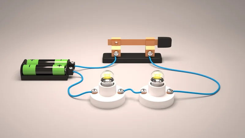
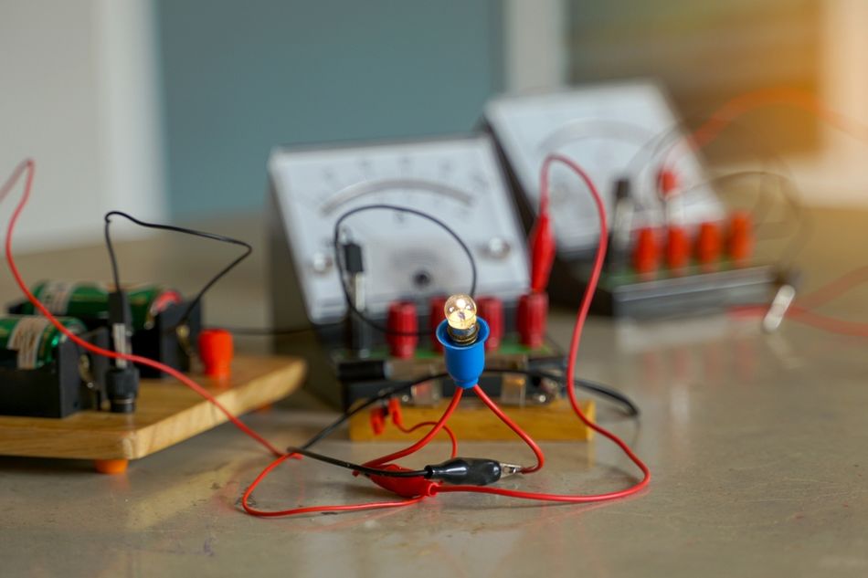
Series Electric Circuit - 3D
Introduction
In electrical engineering, understanding the flow of current through various types of circuits is essential for designing and analyzing any complex system. One fundamental configuration that professionals frequently encounter is the series circuit. So, what is a series circuit? It is a type of electrical circuit in which components are connected end-to-end in a single path, allowing current to flow uniformly through each element. The answer to, what is a series circuit, provides valuable insight into how voltage, resistance, and current behave in a single continuous loop.
Engineers often rely on series circuits in applications where uniform current is required across all components, like in string lights, simple sensors, and analog meters. But what is a series circuit in terms of behavior, voltage distribution, and limitations? These aspects are critical when evaluating system performance and reliability. Let’s start with the basic introduction!
Introduction to Series Circuits
Definition and Simple Explanation
The series circuit is a type of electrical circuit in which all components are connected end-to-end in a single continuous loop. [1] In this configuration, the same current flows through each element sequentially—there is only one path for the electric charge to travel. This type of series connection is often visualized as linking components like a chain: if one link breaks, the entire circuit fails.
In practical terms, this means the same current flows sequentially through each component, as there is only one path for the electric charge to take. If you imagine linking components end-to-end like a chain, you have a series connection.
For example, a series circuit ensures all elements receive the same current, regardless of their order. However, the voltage drop across each component can differ based on its resistance, a concept governed by Ohm’s Law and explored in more detail below:
Basic Characteristics
The series configuration has a few fundamental characteristics that can be summarized as follows:
1. Single Path for Current
There is only one path for current in a series circuit, so the current is identical through every component. In terms of the equation:

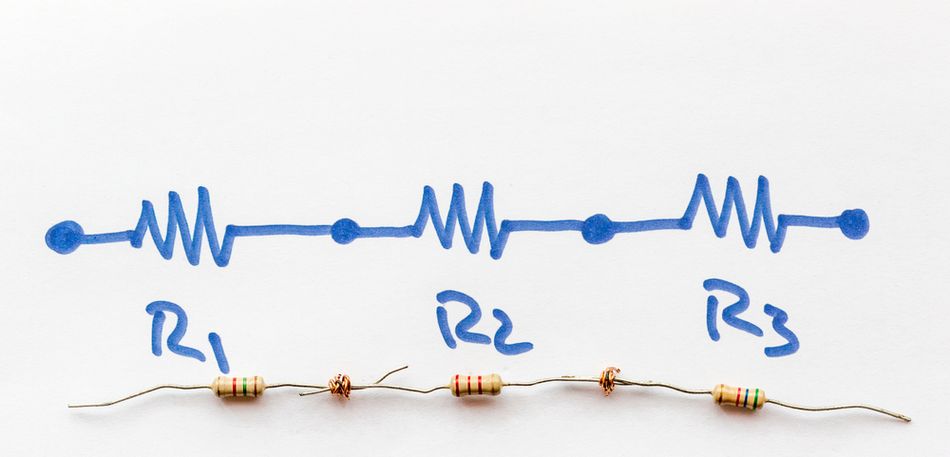
If a 5 amp current leaves the power supply, that same current flows through every component: R1, R2, etc. There’s no room for branching or splitting, which distinguishes it from parallel circuits.
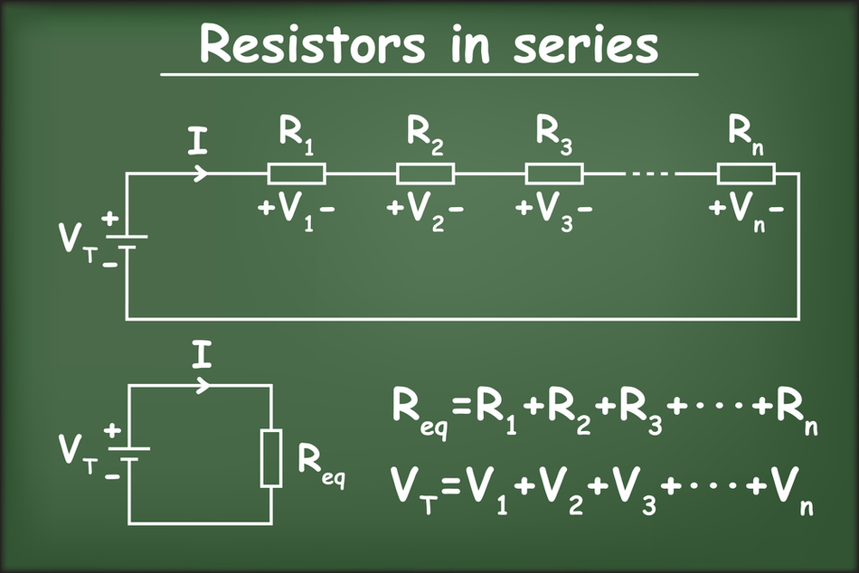
2. Additive Resistances
The total resistance in a series circuit is the sum of all individual resistances:

This means every additional resistor, inductor, or resistive wire adds to the resistance of the circuit. This principle is fundamental to circuit analysis and determines the maximum current the circuit can sustain.
3. Voltage Division
In a series setup, the total voltage from the source is divided across components according to their resistances. This results in individual voltage drops, with higher resistance components dropping more volts:

This behavior is called the voltage divider effect and is widely used in practical applications like sensing and biasing circuits.
4. Dependency of Components
A critical design consideration is that all components in a series loop are interdependent. If one fails (opens), it disrupts the entire circuit; no current flows. Likewise, bypassing or short-circuiting a component alters the equivalent resistance and disturbs regular operation. This "all-or-nothing" behavior is both a strength and a limitation of series circuits.
These characteristics can be observed in even the simplest series circuit. For instance, consider a battery connected to a single resistor: that alone is a series circuit (with only one component). The current flows out of the battery, through the resistor, and back to the battery – one path. The total resistance is simply the resistance of that one resistor.
The resistor drops the entire voltage of the battery! Now, suppose you connect two resistors in series to the same battery. In that case, the current still has only one path (through both resistors in turn), the total resistance is R1 + R2, and each resistor will drop part of the battery voltage (their drops adding to the battery voltage). If one resistor is removed, the circuit opens, and the current ceases. [2]
Recommended Reading: Types of Circuits: A Comprehensive Guide for Engineering Professionals
Series vs Parallel Circuits
In electronics, components can be connected in different ways, with series and parallel being the two fundamental configurations. We’ve defined the series case – a single-path loop. Now let’s contrast that with a parallel circuit and highlight key differences:
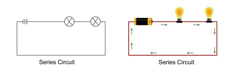
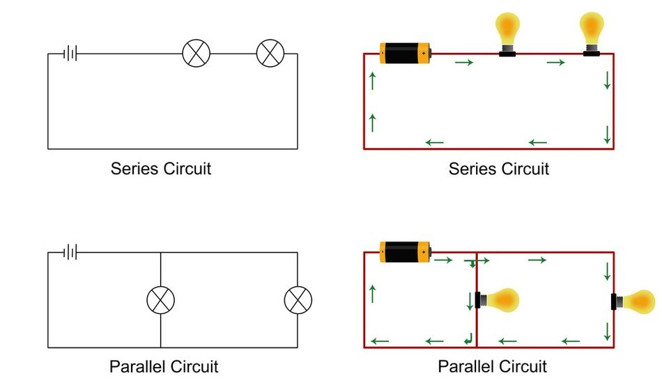
Series Circuit: In a series circuit, all components are connected in a line, one after the other, forming a single path for electric current. Every circuit component experiences the same current, while the voltage drop is distributed among them based on each resistor’s value. If you were to answer, “what is a series circuit?” in one line, it’s a circuit where all elements are in one line (one loop) carrying the same current.
Parallel Circuits: In a parallel circuit, components are connected across the same two points or nodes, creating multiple independent paths for current. Each component (or branch) in parallel has the same voltage across it (equal to the source voltage for that branch), but the currents through the branches can differ. If there are two resistors connected in parallel across a battery, full voltage of the battery appears across each resistor simultaneously, but each resistor carries its current based on its resistance. The total current from the source is the sum of the branch currents (since charge splits among the paths). If one branch is broken (one component fails open), current can still flow in the other branches – they are not dependent on each other in the way series components are.
The crucial difference lies in how added components affect circuit behavior!
In a series circuit, adding more resistors increases the total resistance, which lowers the total current drawn from the source for a given voltage (Ohm’s Law).
In a parallel connection, adding branches decreases equivalent resistance, allowing more current to flow overall.
From an engineering perspective, both configurations serve distinct roles! Series circuits are simple, cost-effective, and ensure uniform current flow through all components—ideal for devices like light strings and simple sensor arrays. On the other hand, parallel circuits are more robust, ensuring equal voltage distribution and independent operation.
In many real circuits, you’ll find combinations: some components might be in series within a branch of a larger parallel network, leading to a series-parallel hybrid. For complex circuits, understanding the difference between these two basic modes of connection is essential, as it affects how you calculate circuit values and predict circuit behavior.
Recommended Reading: Parallel vs Series Circuits: Differences, Theory, and Practical Applications
Components and Principles
Role of Resistors
In a series circuit, the resistor is the foundational component used to demonstrate how electrical quantities behave. When multiple resistors are connected in series, their individual resistances combine directly. The result is a cumulative total resistance that is higher than any single component on its own. Mathematically, this relationship is expressed as:

This additive behavior arises because each resistor impedes the flow of current, and in a single path configuration like a series circuit, these impedances stack linearly.
For example, connecting a 5 Ω resistor and a 10 Ω resistor in series gives a circuit resistance of 15 Ω. According to Ohm’s Law (I = V/R), this increase in resistance—assuming a fixed supply voltage—reduces the amount of current flowing through the entire circuit. Therefore, one everyday use of resistors in series is to limit current deliberately. Engineers often place a resistor in series with a sensitive component (like an LED) to ensure it receives only the safe current it needs, while the excess voltage is dropped across the resistor.
One notable application is voltage division! When resistors are connected in series, each one drops a portion of the total voltage based on its resistance value relative to the equivalent resistance of the network. This behavior is known as the voltage divider effect. For instance, if one resistor is larger than the other, it will experience a larger voltage drop. This principle enables engineers to "tap" a specific potential difference from a higher supply voltage, which is essential for analog biasing, signal conditioning, and generating reference voltages.

Such techniques are widely used in analog electronics and practical applications requiring precise voltage control.
It's essential to recognize that these principles extend beyond just labeled resistors. If there’s any component exhibiting resistance, such as wires, thermistors, or heating elements, that contributes to the total resistance in the same additive way when placed in a series connection. Similarly, other components like inductors and capacitors follow their own rules: inductors in series add their inductances, while capacitors in series reduce to a lower equivalent capacitance, governed by:

However, for most basic DC circuit analysis and entry-level AC circuits, understanding the behavior of resistors in series provides a strong conceptual foundation.
Ohm’s Law and Voltage Drop
One of the powerful aspects of series circuits is how directly Ohm’s Law applies to them. This law states:

This fundamental relationship links voltage (V), current (I), and resistance (R). In a series connection, this equation is valid both for the entire circuit and for each individual component within it.
Applying Ohm’s Law at the Circuit Level:
In a series circuit, the same current flows through all components, and the total resistance is the sum of all individual resistances:

The total voltage from the power supply is distributed across the components, and the overall current can be found using:

This calculated current is uniform throughout the circuit and is used to determine the voltage drop across each resistor.
Voltage Drops Across Components
In terms of components, each resistor in a series circuit has a voltage drop proportional to its resistance:

Since the current flow is constant through all components, any variation in voltage drop arises solely from differences in resistance. A larger resistor will produce a greater voltage drop, while a smaller resistances result in lower drops. The sum of these individual voltage drops always equals the supply voltage, as confirmed by Kirchhoff’s Voltage Law, which states:
The sum of the voltage drops in a closed loop equals the total voltage supplied!
Example: Applying Ohm’s Law
Let’s consider a practical example! Here, a 10 V battery is connected in series with resistors:

Total Resistance:

Circuit Current:

Voltage Drops:


This illustrates that the 15 Ω resistor receives the larger voltage drop due to its greater resistance!
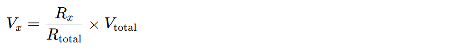
The Voltage Divider Rule
This proportional distribution of voltage in a series circuit leads to a general formula, known as the voltage divider rule:
Using our example:

This rule enables engineers to design circuits that output a specific potential difference without explicitly solving for current, a powerful tool in circuit analysis and design.
Diagnostic Insight: Open Circuits and Troubleshooting
If any component in the series circuit fails open (i.e., is disconnected), the total resistance becomes effectively infinite. Resultantly, the current flow drops to zero:
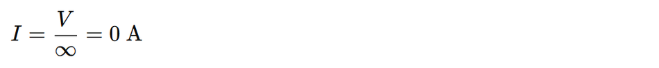
With no current, no voltage drop occurs across the remaining components. Instead, the full supply voltage appears across the open segment. This behavior is central to troubleshooting series networks. For instance, if a resistor unexpectedly shows the full supply voltage, it may indicate that no current is passing through it—possibly due to a break in the entire circuit.
In summary, using Ohm’s Law in series circuits is straightforward and powerful! It allows you to determine the current flow with ease, compute individual voltage drops, and design predictable voltage dividers. The voltage drop in each resistor is directly proportional to its resistance, a fact that we leverage to create reference voltages in circuits. The consistency of current in series, combined with the linear voltage division, makes series circuits a cornerstone concept for understanding more complex circuit analyses.
Recommended Reading: Understanding Circuit Board Components: A Comprehensive Guide
Practical Applications and Uses
Series circuits, being one of the simplest connection topologies, appear in various applications – some intentionally, others as a consequence of how a circuit is designed.
Here are several common and notable uses of series circuits:
Voltage Divider Networks: By placing two (or more) resistors in series across a voltage source, you can tap from the junction to get a fraction of the source voltage. This is widely used to generate reference voltages or interface one voltage level to another. For example, using two resistors in series to scale down a high voltage to a lower value (safe for measurement or feeding into a microcontroller ADC) is a classic technique. The lower resistor in the divider “sees” a reduced voltage proportional to the ratio of resistances, allowing sensitive components to measure or use it. Voltage dividers are found in sensor circuits, feedback networks of voltage regulators, and many analog circuit biasing arrangements.
Current Limiting: Anytime you need to limit the current through a device, a series element is the simplest solution. One typical example is the resistor placed in series with an LED. LEDs require current limiting – without a resistor, they can draw too much current and burn out when directly connected to a voltage source. The series resistor drops the excess voltage and sets a stable current as per Ohm’s Law, protecting the LED. Similarly, in startup circuits or sensor inputs, a series resistor can prevent large surge currents or restrict current to a safe level. Inductors are also sometimes used in series for current limiting in AC or transient conditions, but the principle remains that adding a series element can control current flow.
Series Lighting Strings: In traditional incandescent mini-bulb strings, multiple bulbs are wired in series so that the household voltage (e.g., 120 V or 230 V) is divided across perhaps 20–50 bulbs. Each bulb thus sees only a fraction of the full voltage. For instance, ten lights in series on a 230 V line would each get about 23 V if they have equal resistance (since 230 V/10 = 23 V per bulb). The downside, as many are aware, is that if one bulb blows out (fails open), it breaks the circuit, and the entire string goes dark. This “one out, all out” behavior is a direct consequence of the series design. Modern holiday lights often include shunts or are wired in parallel subsets to mitigate this, but many decorative light strands still effectively behave as series circuits. Series connections are also used in some flashlight designs, where multiple battery cells and bulb filaments are connected in a single chain.
Batteries in Series (Higher Voltage Supplies): Batteries are frequently connected in series to provide a higher voltage output. For example, two 1.5 V AA cells in series yield 3 V, and six 2 V lead-acid cells in series yield a 12 V car battery. In these cases, each cell is a “component” contributing its voltage to the total, much like resistors adding their drops (except here we add sources). The current that flows through the string of cells is the same through each cell. Series wiring of batteries is common when a device or system needs a voltage higher than what a single cell can offer. Many electronics use battery packs that are internally a combination of series and parallel cells to achieve the desired voltage and capacity.
Circuit Conditioning & Filtering: In more advanced electronics, series components are used in impedance matching and filtering networks. For instance, to match the impedance of a circuit to a source or load, engineers might add a series resistor or inductor to tweak the total impedance seen. A series inductor can also serve as a choke to block high-frequency noise, forming a low-pass filter in conjunction with other elements. Likewise, series capacitors are used for AC coupling. In RF engineering and power electronics, combinations of inductors and capacitors in series tune circuits to resonate at certain frequencies or filter out unwanted frequencies. For example, adding a series inductance can raise the total inductive reactance, helping to shape frequency response or match an antenna’s impedance to a transmitter’s output. These uses leverage series connections to control how voltages and currents distribute in the frequency domain, beyond just simple DC considerations.
Series Components in Safety Circuits: Sometimes, safety or control devices are intentionally placed in series with loads. A basic example is a fuse or circuit breaker in series with the appliances it protects. All the current to the appliance goes through the fuse; if the current exceeds a safe value, the fuse blows (opens), interrupting the series path and cutting off power. Similarly, an on/off switch is wired in series with the device it controls – when you open the switch, you create a break in the series loop, stopping current. Multiple switches or relays can be placed in series (forming a logical AND condition for current flow – all must be closed for current to flow). This is common in interlock systems where several conditions must all be actual (switches closed) for a machine to run.
In practice, pure series circuits are not extremely common in complex electronics due to the all-or-nothing current flow issue and the desire for stable voltages for each component. [1] More often, series elements exist as parts of a larger network. However, understanding series behavior is critical whenever you do encounter a chain of components depending on one continuous current. If you’re stringing LEDs, designing a resistor ladder DAC, or assembling battery cells, the series circuit principles ensure you can predict how your system will behave. For any of the above applications, calculating the proper resistor values, current draw, or voltage distribution using series circuit formulas is an essential engineering step.
Recommended Reading: Power Management for Tomorrows Innovations
Advantages, Disadvantages & Troubleshooting
Advantages of Series Circuits
Series circuits offer a few notable benefits in appropriate situations! First, they are simple in design and easy to construct – you can often connect components in a single line without needing complex node junctions. This reduces wiring requirements, lowers material costs, and simplifies assembly. For instance, connecting a light bulb string in series requires only a single wire route between elements—far less wiring than a parallel circuit, which demands a separate connection to each circuit component.
Because the same current passes through all devices in a series connection, current regulation becomes very straightforward. Only one current needs to be monitored or controlled, making it ideal for applications like LED strings or sensor excitation, where uniform current is required. Additionally, a single ammeter placed anywhere in the entire circuit will give an accurate reading of the total current; this simplicity aids in both measurement and control.
Another advantage is ease of analysis! Engineers and students alike benefit from the intuitive nature of series circuit equations: total resistance is just the sum of individual resistances, and Ohm’s Law applies uniformly across the loop. These traits make series circuits ideal for educational settings and basic electronic design.
Disadvantages of Series Circuits
Despite their simplicity, series circuits also have notable drawbacks that limit their use in complex or critical systems. The most significant limitation is component interdependence. If any component fails open, breaking the single path, current flow through the entire circuit stops. This "all-or-nothing" behavior is unacceptable in systems requiring fault tolerance. For example, you wouldn't wire household lights in series; one burnt-out bulb would darken the entire house.
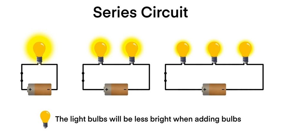
Another issue is voltage division! In a series circuit, the voltage drop is shared among all components. This means no single element receives the full supply voltage unless it's the only load in the circuit. Devices that require the full supply voltage may not function properly if placed in series with others. Furthermore, adding more elements in series increases the total resistance, which reduces the current flow. For loads such as heating elements or lamps, this could mean lower brightness or performance unless the supply voltage is adjusted accordingly.
In summary, series circuits are best suited for scenarios where uniform current, low complexity, and shared behavior are acceptable. They are not ideal when individual component operation or consistent voltage per device is necessary.
Troubleshooting Series Circuits
Because of the single-path nature of a series circuit, troubleshooting is typically straightforward.
Failures usually occur in one of two modes: an open circuit (a break in continuity) or a short circuit (an unintended bypass around a component).
Open-Circuit Faults
If a series circuit suddenly stops working, no current flows, and all devices are off, it likely has an open circuit. This may be due to a loose wire, broken resistor, or failed switch. A simple method to locate the fault is to measure voltage drops along the series path:
In a healthy circuit, each component should have a voltage drop, and all drops should add to the supply voltage.
If one component shows the entire source voltage across its terminals, it is likely open; no current flows beyond that point.
For example, in a string of series-connected light bulbs, the bulb with full line voltage across it (and no illumination) is likely the faulty one.
Short-Circuit Faults
A short circuit occurs when a component is bypassed, either unintentionally or due to internal failure, resulting in near-zero resistance. This reduces the total resistance, which increases the current flow. In a series circuit, symptoms include:
Excessive current draw
Blown fuses or overheated components
One element showing near 0 V voltage drop, while others appear normal
Use a voltmeter to measure across each component! The one with no appreciable voltage drop may be shorted. Feeling components for heat or using thermal imaging can also help detect issues due to elevated current.
General Series Troubleshooting Tips
In practice, series circuits often appear as segments within larger systems. Whether standalone or embedded, the diagnostic steps are:
Use a continuity tester or ohmmeter (with power off) to check if the path is unbroken.
Infinite resistance indicates an open path; abnormally low resistance suggests a possible short.
Always inspect individual resistors, connectors, and solder joints for faults.
In summary, series circuits are easy to understand but require careful consideration in design! They are best applied in scenarios where simplicity and shared current are advantageous, and where the failure of one element disabling the whole circuit is acceptable or can be mitigated. If things go wrong, the diagnostics are conceptually simple – either the path is broken or something is shorted – but finding the exact location of a fault is usually a matter of checking each series element in turn.
Modern devices often avoid long series strings of components for critical functionality, precisely to sidestep these issues, using series elements mainly for specialized purposes. Nonetheless, knowledge of series circuits is indispensable for any engineer or student, as it lays the groundwork for tackling more complex circuit networks.
Recommended Reading: Open Circuit vs Short Circuit: Core Differences between Open and Closed Circuit
Conclusion
Series circuits form the foundation of many essential concepts in electronics. In this article, we explored how current flows through a single path, how total resistance is additive, and how voltage drops distribute proportionally—governed by Ohm’s Law. While simple in structure, series circuits are vital for designing voltage dividers, protecting components, and powering devices like light strings and multi-cell batteries. Their predictable behavior makes them ideal for learning and practical applications alike.
Though pure series circuits are uncommon in isolation, they often appear as segments within larger networks. If you’re designing analog systems, PCB layouts, or power supplies, understanding series circuit behavior is crucial. It enables engineers to simplify sub-networks, calculate current and voltage with ease, and avoid pitfalls such as single-point failures. Mastering series principles equips you to tackle more complex circuits with confidence and precision, making it a must-have skill in every engineer’s toolkit.
Frequently Asked Questions (FAQs)
Q1: What is the main difference between series and parallel circuits?
A: In a series circuit, components share one current path. In parallel circuits, each branch gets the same voltage. Series circuits cease to function if one component fails; parallel branches, however, continue to operate independently.
Q2: Is the current the same through each component in a series circuit?
A: Yes, the same current flows through every element in a series connection, since there’s only one path for electric charge to move through the entire circuit.
Q3: What are the advantages of series circuits?
A: Series circuits are simple to build, need less wiring, and provide consistent current flow. Calculations are straightforward, and they're particularly well-suited for current-limiting setups, such as LED strings or sensor chains.
Q4: What are the disadvantages of series circuits?
A: A single failure breaks the entire circuit. Components cannot function independently, and the voltage from the power source must be shared. Additionally, the higher resistance of a series circuit reduces the current flow.
Q5. Where are series circuits used in real life?
A. An example of a series circuit includes old-style decorative light strings powered by a 12-volt battery. You’ll also find them in voltage dividers, battery packs, and circuits controlled by inline switches or fuses.
References
[1] BBC. Series circuits - Electricity - KS3 Physics [Cited 2024 July 29] Available at: Link
[2] Lumen. Resistors in Series and Parallel | Physics [Cited 2024 July 29] Available at: Link
[3] EBSCO. Electric Circuits: Parallel vs. Series, Diagrams and Components [Cited 2024 July 29] Available at: Link
[4] Wevolver. Parallel vs Series Circuits: Differences, Theory, and Practical Applications [Cited 2024 July 29] Available at: Link