How to Discharge a Capacitor: A Comprehensive Guide for Engineers
Capacitors store electrical energy, similar to batteries, and are used in many electronic devices. Due to their voltage-storing nature, handling them can be dangerous. This article outlines various techniques and safety measures to safely discharge capacitors.

Last updated on 12 Jul, 2024. 25 minutes read
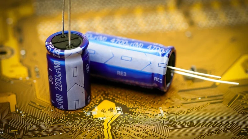
Electronic Capacitor on a PCB
Introduction
A capacitor is a vital component in electronic circuits, storing electrical energy between two conductive plates. These versatile devices are essential in power supplies, signal processing, and energy storage systems, enhancing the functionality of everyday electronics like smartphones, computers, and household appliances.
Capacitors consist of two conductors separated by an insulating material, such as ceramic, air, or impregnated paper. When a power supply creates a potential difference between the plates, the capacitor stores charge until its voltage matches the supply voltage. This ability to store charge is called capacitance, measured in Farads (typically in picofarads, nanofarads, microfarads, or millifarads), and it depends on the surface area of the plates, the distance between them, and the type of dielectric material used.
Proper discharge of capacitors is crucial for safety and component longevity, as they can retain dangerous voltage levels long after power is removed. Controlled discharge protects both personnel and sensitive circuit elements from unexpected energy release. Additionally, capacitors block DC while passing AC, ensuring smooth power supply outputs and clean signal transfer, making them indispensable in various electronic applications.
Why do Capacitors Need to be Discharged?
As earlier mentioned, capacitors store electric charge and they can hold this charge even if the main power supply is removed. Discharging a capacitor means releasing the charge stored within the capacitor.
Accidentally or carelessly touching the leads of the capacitor after disconnecting the power supply, on the misconception that the absence of a power supply makes it harmless, can bear consequences ranging from mild tingling or burn to fatal electrocution and fire, depending on the amount of charge present in the capacitor. Large capacitors can store enough energy to inflict injuries, so they must be appropriately discharged.
When a capacitor is disconnected, it retains its accumulated voltage (and current) across the previously connected terminals, which is notably dangerous. This is why it is imperative to discharge a capacitor before disconnecting it to remove all charges and corresponding voltage.
A short circuit of a charged capacitor poses a great risk of burning out the electronic component and other circuit elements. The greater the capacitance and voltage of the capacitor, the greater the damage it can potentially cause.
How to Discharge a Capacitor
1. Manual Discharge Techniques
Manual discharge of capacitors is a critical skill for electronics professionals. The following step-by-step procedure outlines a safe manual discharge method:
Verify power is disconnected and capacitor is isolated from the circuit.
Select an appropriate discharge resistor based on capacitor voltage and capacitance.
Connect the discharge resistor across the capacitor terminals using insulated probes.
Monitor voltage decay using a high-impedance voltmeter in parallel with the resistor.
Maintain the connection until voltage drops below 50V or to the specified safe level.
Short the capacitor terminals with an insulated shorting stick as a final safety measure.
Circuit analysis for this method: V(t) = V₀e^(-t/RC) Where V₀ is initial voltage, R is discharge resistance, and C is capacitance.
Discharge resistor selection criteria:
Power rating: P = V²/R (use peak voltage for safety margin)
Resistance value: R = V/I, where I is the desired initial discharge current
Thermal considerations: Choose a resistor with adequate heat dissipation capability
Pros and cons of manual discharge techniques:
Resistive Discharge:
Pros: Simple, cost-effective, controllable discharge rate
Cons: Slow for large capacitors, resistor heating issues
Shorting Bar:
Pros: Fast discharge, suitable for low-voltage capacitors.
Cons: Risk of arc flash, high peak currents, potential component damage.
Voltage-Dependent Resistor (VDR):
Pros: Non-linear discharge, limits initial current surge.
Cons: More complex, specific to voltage range.
Comparison table of manual discharge methods:
Method | Discharge Time | Energy Dissipation | Safety Factor |
100Ω Resistor | 5RC (500ms*) | V²/2R (50J*) | High |
10Ω Resistor | 0.5RC (50ms*) | V²/2R (500J*) | Medium |
Shorting Bar | <1ms | V²/2ESR (1000J*) | Low |
VDR (V₁₅₀LA10A) | ~100ms | Variable (~100J*) | High |
Assuming 1000μF capacitor charged to 100V
Discharge time calculation: t = -RC ln(V_final / V_initial) Where t is time, R is resistance, C is capacitance, V_final is target voltage, and V_initial is starting voltage.
Effects of initial voltage and target residual voltage:
Higher initial voltage increases discharge time logarithmically. This means that higher initial voltages result in longer discharge times, following a logarithmic relationship.
Lower target residual voltage increases discharge time linearly. A lower target residual voltage requires more time to discharge the capacitor completely.
Impact of lead inductance and capacitor ESR:
Lead inductance (L) creates an LCR circuit, potentially causing voltage oscillations during fast discharges
ESR (Equivalent Series Resistance) affects the initial discharge rate and power dissipation
Mitigation methods:
Use low-inductance discharge paths (wide, short PCB traces or thick, short wires)
Add a small series inductor to dampen oscillations in low-ESR capacitors
Consider the total circuit resistance (R_total = R_discharge + ESR) in discharge calculations
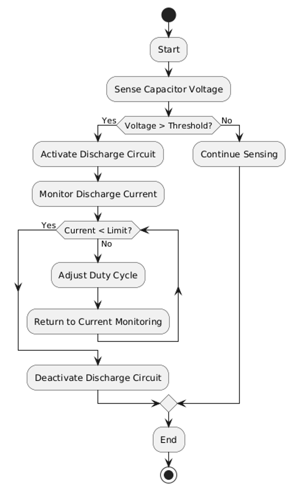
2. Automated Discharge Systems
Automated discharge systems employ electronic circuits to safely and efficiently discharge capacitors without manual intervention. The fundamental principle involves using controlled switching elements and energy dissipation components to manage the discharge process.
Circuit analysis of a basic automated discharge system:
Sensing circuit: Vout = k * Vcap (where k is the voltage divider ratio)
Comparator: Vout = Vcc when Vsense > Vref, else Vout = 0
Switching element: MOSFET or relay controlled by comparator output
Discharge path: R_discharge = V_initial / I_max
Component selection criteria:
Voltage divider resistors: High impedance (>1MΩ) to minimize leakage
Comparator: Low input bias current (<1nA) for accurate sensing
Switching element: Voltage rating > 2 * V_max, current rating > 2 * I_max
Discharge resistor: Power rating > V_max^2 / R_discharge
Types of automated discharge systems:
Passive systems:
Use normally-closed relays or depletion-mode MOSFETs
Activate discharge path upon power loss
Simple and fail-safe, but limited control over discharge profile
Active systems:
Employ microcontroller-based control
Offer programmable discharge profiles
Provide real-time monitoring and data logging capabilities
Regenerative systems:
Recover stored energy instead of dissipating it as heat
Use DC-DC converters or inverters to return energy to the source
Higher efficiency but more complex and costly
Advantages of automated discharge methods:
Consistent and repeatable discharge profiles
Reduced risk of human error
Capability to handle high voltage and energy levels safely
Limitations:
Initial cost and complexity
Potential for system failure or malfunction
May require periodic calibration and maintenance
Quantitative comparison:
Manual resistive discharge (100Ω): t_discharge ≈ 5RC, efficiency ≈ 0%
Active automated system: t_discharge ≈ 2RC, efficiency up to 95%
Regenerative system: t_discharge ≈ 3RC, energy recovery up to 85%
Discharge control algorithms:
Constant Current:
Maintain I = V/R by adjusting duty cycle of switching element
Advantages: Predictable discharge time, uniform component stress
Implementation: Use current sensing resistor and PID control loop
Constant Power:
Maintain P = VI by adjusting current as voltage decreases
Advantages: Optimal energy dissipation, shorter discharge time
Implementation: Multiply sensed voltage and current, use lookup table for control
Adaptive Methods:
Adjust discharge profile based on capacitor characteristics
Advantages: Optimized for different capacitor types and states
Implementation: Use machine learning algorithms to predict optimal discharge strategy.
The Fundamentals of Capacitor Behavior
Capacitor Types and Their Discharge Characteristics
Capacitors are fundamental electronic components consisting of two conductive plates separated by a dielectric material. The plate geometry and dielectric properties determine the capacitor's electrical characteristics.
The capacitance (C) of a parallel-plate capacitor is given by the formula:
C = εA/d
Where: ε = permittivity of the dielectric A = area of overlap between the plates d = distance between the plates
The energy (E) stored in a capacitor is calculated using:
E = ½CV²
Where V is the voltage across the capacitor.
Different types of capacitors exhibit unique electrical characteristics:
Electrolytic Capacitors:
High capacitance values
Polarized (must be connected with correct polarity)
Relatively high ESR (Equivalent Series Resistance)
Prone to leakage current
Ceramic Capacitors:
Low to medium capacitance values
Non-polarized
Low ESR
Excellent high-frequency performance
Film Capacitors:
Medium capacitance values
Non-polarized
Low ESR
Good stability and reliability
Supercapacitors:
Extremely high capacitance values
Low voltage ratings
High energy density
Discharge characteristics vary among capacitor types due to their internal structure and materials. The discharge behavior is typically modeled using an exponential decay function:
V(t) = V₀e^(-t/τ)
Where: V(t) = voltage at time t V₀ = initial voltage τ = time constant (τ = RC, where R is the discharge resistance)
Table: Comparison of Capacitor Discharge Characteristics
Capacitor Type | Time Constant | Energy Storage Capacity | Discharge Rate |
Electrolytic | Long | High | Slow |
Ceramic | Short | Low | Fast |
Film | Medium | Medium | Medium |
Supercapacitor | Very long | Very high | Very slow |
Further reading: Supercapacitor FAQ
Dielectric absorption is a phenomenon where a capacitor that has been fully discharged may spontaneously redevelop a voltage across its terminals. This effect is more pronounced in certain dielectric materials, particularly those used in electrolytic and film capacitors. Dielectric absorption can impact the discharge behavior by causing the capacitor to retain a small charge even after apparent full discharge, potentially leading to safety hazards or unexpected behavior in sensitive circuits.
Understanding Capacitor Ratings and Safety Thresholds
Capacitor ratings are crucial parameters that define the operational limits and performance characteristics of these components. The key ratings include:
Voltage Rating: The maximum continuous voltage that can be safely applied across the capacitor. Exceeding this rating can lead to dielectric breakdown and capacitor failure.
Capacitance: The amount of electrical charge the capacitor can store per unit voltage, measured in farads (F).
Temperature Range: The range of temperatures within which the capacitor can operate safely and maintain its specified performance.
Frequency Range: The range of frequencies at which the capacitor can effectively operate, is particularly important for AC applications.
Voltage derating is a critical concept in capacitor selection and use. It involves operating the capacitor at a voltage lower than its rated voltage to enhance reliability and extend its lifespan. Derating curves provided by manufacturers illustrate how the maximum safe operating voltage decreases with increasing temperature or frequency.
Also, interpreting datasheet information is essential for safe capacitor discharge. Key parameters to consider include:
Maximum Ripple Current: The highest AC the capacitor can handle without excessive heating.
Voltage Reversal Tolerance: The ability of the capacitor to withstand reverse polarity voltages. This is particularly important for non-polarized capacitors.
Surge Voltage Rating: The maximum short-duration voltage the capacitor can withstand.
Critical safety thresholds for capacitors include:
Breakdown Voltage: The voltage at which the dielectric fails, causing a short circuit.
Maximum Operating Temperature: Exceeding this can lead to accelerated aging and potential failure.
Voltage Coefficient: The change in capacitance with applied voltage, which is crucial for stability in high-voltage applications.
Insulation Resistance: The resistance between the capacitor's terminals and its case. It is important for preventing leakage currents.
Energy storage in capacitors is given by the formula E = ½CV², where C is the capacitance and V is the voltage. However, parasitic elements like equivalent series inductance (ESL) and equivalent series resistance (ESR) can affect the actual energy storage and discharge behavior.
ESR represents the total effect of all resistive components within the capacitor. It affects the capacitor's ability to deliver current quickly and impacts its power dissipation. The dissipation factor, also known as tan δ, is the ratio of the ESR to the capacitive reactance and is a measure of the capacitor's efficiency.
Self-discharge rates and leakage current vary among capacitor types:
Electrolytic Capacitors: Generally have higher leakage currents due to their construction.
Ceramic Capacitors: Typically have very low leakage currents and self-discharge rates.
Film Capacitors: Offer a good balance with moderate leakage currents.
Supercapacitors: Can have significant self-discharge rates due to their high capacitance values.
Essential Safety Precautions
Some general safety precautions when handling capacitors include:
1. Use of Personal Protective Equipment for Capacitor Handling
When handling capacitors, especially those with high voltage or energy storage capabilities, using proper Personal Protective Equipment (PPE) is crucial for ensuring safety. Here are the essential PPE items and their roles:
Insulating Gloves: Rated for the expected maximum voltage (e.g., Class 00 for up to 500V, Class 0 for up to 1000V). These gloves provide primary protection against electric shock.
Safety Glasses or Face Shield: ANSI Z87.1-compliant eye protection to guard against potential arc flash or debris, protecting eyes and face.
Insulating Mats: Rubber mats rated for the working voltage, conforming to ASTM D178 standards. They offer additional ground isolation and protection against step potential.
ESD-Safe Footwear: Shoes with resistance between 10^6 and 10^9 ohms to prevent static buildup and maintain ground isolation. They prevent static discharge that could damage sensitive components or ignite flammable atmospheres.
Insulated Tools: Insulated screwdrivers, pliers, and cutters rated for the voltage (e.g., 1000V rated for work up to 1000V). Insulated tools reduce the risk of accidental short circuits and provide an additional layer of protection.
Further reading: ESD-safe materials: A beginner's guide
Guidelines for selecting appropriate PPE:
Determine the maximum voltage present in the system.
Calculate the potential arc flash energy using IEEE 1584 guidelines.
Select PPE with voltage and energy ratings that exceed the calculated values.
Consider environmental factors such as temperature and humidity.
To calculate minimum insulation requirements:
E = V / d
Where: E = Electric field strength (V/mm) V = Applied voltage (V) d = Insulation thickness (mm)
Ensure that the selected PPE's insulation rating exceeds the calculated electric field strength.
Steps for proper PPE use:
Inspect all PPE for damage or wear before use.
Wear ESD-safe footwear and ensure proper fit.
Put on the insulating mat in the work area.
Wear safety glasses or face shields.
Put on voltage-rated insulating gloves.
Use a glove inflator to check for punctures or leaks.
If using leather protectors, put them on over the insulating gloves.
Ground yourself using an approved grounding strap or method.
Use only insulated, voltage-rated tools for the task.
After work, carefully remove and store PPE properly.
Relevant safety standards and regulations:
Relevant safety standards and regulations ensure workplace safety and compliance with industry norms. They outline guidelines for equipment use, personal protective gear, and operational protocols to mitigate risks and ensure a safe working environment. Adherence to these standards not only safeguards personnel but also promotes consistency and efficiency in industrial practices. Here are some:
NFPA 70E: Standard for Electrical Safety in the Workplace
Article 130.7: Personal and Other Protective Equipment
OSHA 29 CFR 1910.137: Electrical Protective Equipment
IEC 60900: Live Working - Hand Tools for Use Up to 1000V AC and 1500V DC
2. Identifying and Mitigating Potential Risks
Charged capacitors pose significant hazards in electrical systems. The primary risks include electric shock, arc flash, and component damage. Electrical shock thresholds vary, but generally:
1-10 mA: Perception threshold
10-20 mA: Muscular contraction
30-50 mA: Respiratory paralysis
100-300 mA: Ventricular fibrillation
1 A: Sustained myocardial contraction
Assessing a capacitor's charge state is crucial for safe handling. Methods include:
Voltage measurement: Use a high-impedance voltmeter (>10 MΩ) to measure terminal voltage.
Electrostatic field detection: Non-contact voltage detectors can sense residual charge.
Charge recovery voltage monitoring: Measure voltage reappearance after short-circuiting terminals.
Time-domain reflectometry: Advanced technique for assessing internal charge distribution.
Creating a safe work environment involves:
Implementing proper lockout/tagout procedures.
Establishing a designated discharge area with insulating mats.
Ensuring adequate lighting and ventilation.
Providing easily accessible emergency shut-off switches.
Maintaining clear access to fire extinguishers rated for electrical fires.
Risk mitigation strategies:
Design redundant discharge paths with parallel resistors (R1 || R2) to ensure discharge even if one path fails.
Implement automatic discharge circuits using normally-closed relays that engage upon power loss.
Use voltage-dependent resistors (VDRs) for non-linear discharge characteristics, limiting initial current surge.
Install bleed resistors across capacitor terminals for continuous slow discharge.
Employ active discharge circuits with current-limited op-amps for controlled discharge rates.
Electrical isolation and grounding techniques:
Galvanic isolation:
Use isolation transformers with turns ratio 1:1 for power circuits.
Employ optocouplers or digital isolators for signal circuits.
Calculation: Isolation voltage rating > 2 * (Maximum system voltage + Safety margin)
Capacitive isolation:
Implement Y-capacitors for high-frequency noise suppression.
Ensure Y-capacitors meet safety standards (e.g., IEC 60384-14).
Calculation: Maximum leakage current = 2πfCV, where f is line frequency, C is capacitance, and V is RMS voltage.
Safe discharge path design:
Use wire gauge capable of handling peak discharge current: I_peak = V_initial / R_discharge
Ensure power rating of discharge resistor: P_resistor > V_initial^2 / R_discharge
Calculate discharge time constant: τ = R_discharge * C_capacitor
Design for 5τ discharge time to reach <1% of initial voltage
Equipment grounding:
Implement star-point grounding to minimize ground loops.
Use low-impedance grounding straps (<0.1Ω) for high-frequency performance.
Calculate ground impedance: Z_ground = √(R^2 + (2πfL)^2), where R is resistance, L is inductance, and f is the highest frequency of concern.
Best Practices for Efficient and Safe Discharge
Optimizing Discharge Procedures for Different Capacitor Types
Efficient and safe discharge procedures vary depending on the capacitor type. Here are guidelines for common capacitor types:
For electrolytic capacitors, use a resistive discharge method with R = √(L/C) for critical damping, monitor polarity to prevent reverse voltage damage, and allow for reforming time after long storage periods. For film capacitors, employ constant current discharge for uniform energy dissipation, consider self-healing properties in discharge circuit design, and use parallel resistors for redundancy in high-reliability applications. For ceramic capacitors, implement fast discharge methods due to low ESR, be aware of voltage coefficient effects on actual capacitance, and use temperature-compensated discharge circuits for high-stability types.
Adapting techniques based on capacitance and voltage:
For high capacitance (C > 1000μF) and high voltage (V > 1000V): t_discharge = -RC ln(V_final / V_initial) I_initial = V_initial / R_discharge P_peak = V_initial^2 / R_discharge
For low capacitance (C < 1μF) and low voltage (V < 100V): Use active discharge with constant current: I = C * dV/dt
Impact of ESR and leakage current:
ESR (Equivalent Series Resistance):
Affects initial discharge rate: τ_initial = (ESR + R_external) * C
Influences power dissipation: P_ESR = I_discharge^2 * ESR
Compensation: Subtract ESR from external resistance in calculations
Leakage Current:
Creates a parallel discharge path: I_total = I_discharge + I_leakage
Affects long-term storage charge retention
Compensation: Model as a parallel resistor R_leak = V_rated / I_leak_max
Key considerations for each capacitor type:
Electrolytic capacitors exhibit temperature sensitivity, with capacitance increasing by approximately 10% per 10°C rise. They also experience aging, where capacitance decreases by about 2% per 1000 hours at the rated voltage, and typically require voltage derating to 80% of their rated voltage for extended life. Film capacitors possess self-healing capabilities under voltage stress, have low dielectric absorption with minimal charge recovery after discharge, and maintain excellent stability over time and temperature. Ceramic capacitors, on the other hand, have a significant voltage coefficient, with Class 2 dielectrics potentially losing more than 80% of capacitance at the rated voltage. They can also be affected by piezoelectric effects, where mechanical stress induces voltage, and have varying temperature coefficients, which can be either positive (P-type) or negative (N-type).
Further reading: N-Type Vs P-Type: Difference Between P-Type and N-Type Semiconductors
Common Pitfalls and How to Avoid Them
Capacitor discharge processes are prone to several common mistakes that can lead to safety hazards, component damage, or inefficient discharge. Understanding these pitfalls and their underlying physical principles is crucial for safe and effective capacitor handling.
Rapid Discharge Through Short Circuit: When a capacitor is short-circuited, the rate of voltage change (dV/dt) becomes extremely high, resulting in a large current spike. This can cause localized heating, arc formation, and potential damage to the capacitor or surrounding components. The physical principle involved is I= C * dV/dt.
Ignoring Residual Charge: Some capacitor dielectrics can retain charge even after apparent full discharge. This phenomenon, known as dielectric absorption, can lead to voltage recovery and unexpected shocks. The physical principle here is dielectric absorption.
Neglecting Temperature Effects: Capacitance often increases with temperature, affecting discharge time constants and potentially leading to incomplete discharge if not accounted for. This is due to the temperature coefficient of capacitance.
Overlooking Voltage Derating: Operating capacitors at their maximum rated voltage can accelerate aging and increase the risk of dielectric breakdown. Proper voltage derating is essential for long-term reliability. The relevant physical principle is dielectric strength degradation.
Improper Handling of Polarized Capacitors: Reverse voltage application to polarized capacitors, even during discharge, can lead to rapid gas generation, electrolyte vaporization, and potential explosion. This is due to electrolytic formation.
Consequences of improper discharge techniques include:
Potential injury to personnel from electrical shock or flying debris
Immediate capacitor failure or explosion
Damage to surrounding circuit components
Reduced capacitor lifespan due to internal damage
Unreliable system operation due to residual charge effects
Table: Common Discharge Pitfalls and Solutions
Error Description | Potential Consequences | Prevention Methods |
Rapid short-circuit discharge | Component damage, arc flash | Use current-limiting resistors, active discharge circuits |
Ignoring residual charge | Unexpected shocks, system malfunction | Implement extended discharge times, use charge recovery measurements |
Temperature effects neglect | Incomplete discharge, altered time constants | Apply temperature compensation, monitor ambient conditions |
Improper voltage derating | Accelerated aging, dielectric breakdown | Design for 80% or less of rated voltage, use higher voltage rated components |
Mishandling polarized capacitors | Explosion, electrolyte leakage | Clearly mark polarity, use reverse voltage protection circuits |
Failure Modes and Prevention
1. Dielectric Breakdown
Mechanism: Electric field exceeds dielectric strength
Prevention: Proper voltage derating and use of safety margins in design
2. Thermal Runaway
Mechanism: Positive feedback between leakage current and temperature
Prevention: Adequate thermal management and current-limiting discharge circuits
3. Electrolyte Dry-Out
Mechanism: Gradual loss of electrolyte due to heat and voltage stress
Prevention: Operate within the specified temperature range and apply proper voltage derating
Effects of Temperature and Humidity
1. Temperature
Increases capacitance: Compensate by adjusting discharge time calculations
Accelerates chemical reactions: Implement temperature-controlled storage
Affects ESR: Account for ESR changes in discharge circuit design
2. Humidity
Promotes corrosion: Use hermetically sealed capacitors in high-humidity environments
Alters surface leakage: Apply conformal coatings to PCBs
Affects dielectric properties: Monitor and control relative humidity in sensitive applications
Compensation Methods
Use temperature-compensated components in discharge circuits
Implement humidity-controlled environments for critical systems
Apply temperature and humidity sensors for real-time adjustment of discharge parameters
Essential Capacitor Discharge Tools and Equipment
Selecting the Right Discharge Tools
Proper tool selection is crucial for safe and effective capacitor discharge. The following tools are essential for this process:
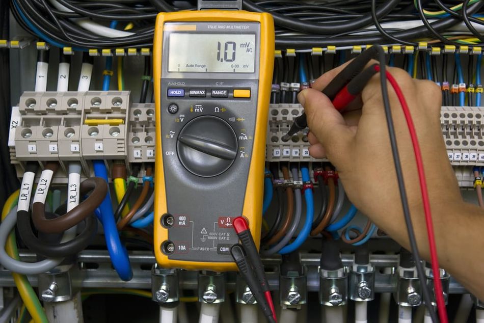
1. High-Voltage Multimeter
Operating Principle: Dual-slope integration ADC
Specifications: 1000V DC range, 10MΩ input impedance, CAT IV 600V safety rating
Function: Accurately measures capacitor voltage before and during discharge
Proper Use: Ensure proper range selection and use high-voltage probes for voltages over 1000V
2. Discharge Resistor
Operating Principle: Energy dissipation through Joule heating
Specifications: Non-inductive, high power rating (>100W), voltage rating >2x capacitor voltage
Function: Safely dissipates stored energy in the capacitor
Proper Use: Calculate the appropriate resistance value based on the discharge time constant
3. Insulated Discharge Probe
Operating Principle: Isolated conductive path with a safety resistor
Specifications: Voltage rating >2x capacitor voltage, integrated current-limiting resistor
Function: Safely makes contact with capacitor terminals
Proper Use: Verify probe integrity before each use and maintain proper hand placement
4. Oscilloscope
Operating Principle: Real-time voltage sampling and display
Specifications: Bandwidth >100MHz, 1MΩ/10pF input, floating ground capability
Function: Monitors discharge waveform and detects anomalies in the discharge curve
Proper Use: Set the appropriate time base and voltage scale, and use differential probes for high voltages
5. Infrared Thermometer
Operating Principle: Measurement of infrared radiation emitted by an object
Specifications: Temperature range -20°C to 400°C, ±2% accuracy, 10:1 distance-to-spot ratio
Function: Monitors the temperature of discharge components to prevent thermal issues
Proper Use: Adjust the emissivity setting for accurate readings on different surfaces
Criteria for selecting appropriate capacitor discharge tools
When selecting appropriate capacitor discharge tools, it's essential to ensure voltage and current ratings exceed maximum expected values by at least 2x and to choose tools with measurement resolution at least 10x finer than the smallest change to be measured. For oscilloscopes, the bandwidth should be at least 5x the highest frequency of interest in the discharge waveform. Safety features such as CAT III or CAT IV ratings, isolated inputs, and proper insulation are crucial. Additionally, it's important to consider environmental factors, opting for tools rated for the expected temperature and humidity conditions to ensure accuracy and reliability in various settings.
Comparison Table of Discharge Tools:
Tool Type | Voltage/Current Rating | Accuracy | Special Features |
Fluke 87V Multimeter | 1000V DC, 10A | ±0.05% DC voltage | True RMS, temperature measurement |
Keysight DSOS054A Oscilloscope | 500MHz bandwidth, 150V max | 8-bit vertical resolution | 12-bit ADC mode, segmented memory |
Megger MIT515 Insulation Tester | 5kV, 3mA | ±5% voltage | Adjustable test voltage, timer |
Raytek MT4 Infrared Thermometer | N/A (Temp: -30 to 400°C) | ±2% or 2°C | Laser sighting, MAX/MIN/DIF/AVG readings |
Technical Specifications and Limitations
High-Voltage Multimeter:
Input impedance: Typically 10MΩ, which can affect readings on high-impedance circuits
Measurement uncertainty: Often ±(0.05% + 2 counts) for DC voltage
Maximum safe operating voltage: Usually 1000V CAT III, 600V CAT IV
Discharge Resistor:
Power derating: Typically 50% at 70°C ambient temperature
Voltage coefficient: Can affect resistance value at high voltages
Pulse handling capability: Limited by thermal mass and construction
Oscilloscope:
Input capacitance: Typically 10-20pF, can affect high-frequency measurements
Vertical resolution: Usually 8 bits, limiting voltage measurement precision
Maximum input voltage: Often limited to 300V CAT II without special probes
Calibration Requirements and Procedures:
Multimeters and Oscilloscopes:
Calibration interval: Typically annual
Procedure: Compare against traceable voltage and current standards
Verification: Check against known reference voltages before critical measurements
Infrared Thermometers:
Calibration interval: Biannual
Procedure: Use a blackbody calibration source at multiple temperature points
Verification: Check against a known temperature reference (e.g., ice bath at 0°C)
Discharge Resistors:
Calibration interval: Not typically calibrated, but resistance should be verified periodically
Procedure: Measure resistance with a calibrated ohmmeter
Verification: Check resistance before each use, especially after high-energy discharges
Specialized Equipment for High-Voltage Applications:
High-Voltage Probe:
Operating principle: Resistive voltage divider with compensation network
Typical specifications: 100kV DC, 75MHz bandwidth, 1000:1 attenuation ratio
Safety features: Corona rings, insulated body, grounded shield
Applications: Power distribution systems, high-energy physics experiments
Isolation Amplifier:
Operating principle: Galvanic isolation using optical or capacitive coupling
Typical specifications: 10kV isolation, 100kHz bandwidth, 0.01% linearity
Safety features: Reinforced insulation, protective impedance
Applications: Medical equipment, industrial process control
Electrostatic Voltmeter:
Operating principle: Non-contact measurement using field effect
Typical specifications: 200kV range, ±0.1% accuracy, >10^14Ω input impedance
Safety features: Fieldmeter design eliminates direct contact with high voltage
Applications: Electrostatic research, high-voltage power supplies
High-Voltage Discharge Switch:
Operating principle: Vacuum or SF6 gas-insulated switching
Typical specifications: 100kV rating, 50kA peak current, <100ns switching time
Safety features: Fail-safe grounding mechanism, remote operation capability
Applications: Pulsed power systems, capacitor bank discharge
Scenarios Requiring Specialized Discharge Tools:
Particle accelerator capacitor banks (>100kV, >1MJ stored energy)
High-voltage DC transmission line maintenance (±800kV systems)
Electromagnetic pulse (EMP) simulator discharge (>200kV, <10ns rise time)
X-ray generator capacitor discharge (150kV, high repetition rate)
Key Features of High-Voltage Discharge Equipment:
Voltage ratings exceeding 100kV DC or AC peak
Partial discharge inception voltage (PDIV) >1.2 times rated voltage
Creepage distances complying with IEC 60664-1 for Pollution Degree 2
Impulse withstand voltage rating >1.5 times maximum operating voltage
EMI/RFI shielding effectiveness >60dB from 1MHz to 1GHz
Safety certifications: IEC 61010-1, EN 61326-1, UL 61010-1
Voltage Isolation and Measurement Techniques:
Capacitive Voltage Divider:
Operating principle: High-voltage and low-voltage capacitors in series
Advantages: High bandwidth, minimal power consumption
Challenges: Stray capacitance effects, temperature sensitivity
Resistive-Capacitive (RC) Divider:
Operating principle: Combines resistive and capacitive division
Advantages: Improved low-frequency response, damping of oscillations
Challenges: Power dissipation in resistive elements, voltage coefficient of resistors
Optically Isolated Measurement:
Operating principle: Voltage-to-frequency conversion with optical transmission
Advantages: Complete galvanic isolation, immune to EMI
Challenges: Limited bandwidth, potential for nonlinearity
Maintenance and Calibration Requirements:
Regular Inspection:
Visual checks for surface contamination, cracks, or corona effects
Measurement of insulation resistance and leakage current
Frequency: Monthly or before each critical measurement
Calibration:
Comparison against traceable high-voltage standards
Linearity checks across full voltage range
Bandwidth verification using step response measurements
Frequency: Annually or after any repair/modification
Environmental Control:
Maintain controlled temperature and humidity in storage and use
Implement dust-free environments for sensitive equipment
Use desiccants or dry air purging for moisture-sensitive components
Component Replacement:
Replace high-voltage resistors every 5 years or 10,000 operating hours
Inspect and replace gaskets and seals in pressurized systems annually
Regenerate or replace desiccant in sealed units as per manufacturer guidelines.
Discharging a capacitor safely and effectively involves a few key techniques, all requiring the use of a multimeter to check the stored voltage before proceeding. The multimeter, whether analog or digital, measures the capacitor's voltage to ensure accurate and safe discharge.
Steps to Discharge a Capacitor:
Cut off the Power: Ensure the capacitor is completely disconnected from any power source.
Measure Voltage: Use a multimeter set to voltage reading to check the capacitor's stored voltage.
Select Discharge Method:
For voltages below 50V, an insulated screwdriver can be used.
For higher voltages, use an appropriate resistive material such as a bleeder resistor.
Discharging with a Screwdriver:
Hold the capacitor by its base without touching the terminals.
Use an insulated screwdriver to touch both terminals simultaneously, causing the capacitor to discharge.
Check the voltage again; repeat if necessary until the voltage is zero.
Using a Bleeder Resistor:
Connect a bleeder resistor across the capacitor terminals.
Wait for the calculated discharge time based on the capacitor's specifications.
Verify the voltage with a multimeter to ensure complete discharge.
Using a Light Bulb:
Connect a light bulb with appropriate power rating to the capacitor terminals.
The bulb will glow as the capacitor discharges, and will go out when fully discharged.
Verify with a multimeter.
Creating a DIY Discharge Tool:
Gather materials: electrical tape, alligator clips, 12-gauge wire, and a 50W 20k ohm resistor.
Prepare and connect the wires to the resistor and alligator clips.
Secure connections with electrical tape.
Connect the clips to the capacitor terminals to discharge.
Using a Discharge Pen:
Connect the pen's black lead to the capacitor’s cathode and the red lead to the anode.
The pen discharges the capacitor safely.
Safety and Accuracy: Always wear protective gear such as insulated gloves and ensure tools are in good condition. Regularly verify and calibrate your tools for accuracy. For higher voltage capacitors, avoid using methods like the screwdriver and opt for safer, specialized equipment.
Conclusion
Capacitor discharge is a critical process in electrical engineering, requiring a deep understanding of capacitor physics and behavior. This comprehensive guide has explored the intricacies of discharge methods, safety protocols, and troubleshooting techniques. The importance of proper discharge procedures cannot be overstated, as improper handling can lead to equipment damage, system failures, or even personal injury. Engineers must remain vigilant in applying safety measures and utilizing appropriate tools and techniques for each specific application. As technology advances, new challenges in capacitor discharge will emerge, necessitating continuous learning and adaptation. By applying the knowledge and best practices outlined in this guide, engineers can ensure safe, efficient, and reliable capacitor discharge across a wide range of applications, contributing to the overall advancement of electrical systems and technologies.
Frequently Asked Questions
Q: How does temperature affect capacitor discharge rates, and how can this be compensated for in high-precision applications?
A: Temperature significantly influences capacitor discharge rates due to its effect on dielectric properties and ESR. The discharge time constant τ = RC can vary with temperature as follows:
Capacitance change: Typically 0.1% to 1% per °C, depending on dielectric material
ESR change: Can increase or decrease, often 0.5% to 2% per °C
Compensation methods:
Temperature-compensated discharge circuits using thermistors or PTC resistors
Active temperature monitoring and real-time discharge parameter adjustment
Use of temperature-stable capacitor types (e.g., NP0/C0G ceramics)
In high-precision applications, combining these methods with environmental control can achieve temperature stability better than ±0.01% over a 50°C range.
Q: What are the challenges and best practices for discharging large capacitor banks in renewable energy systems?
A: Challenges in discharging large capacitor banks in renewable energy systems include:
High stored energy (often >1 MJ)
Potential for arc flash during discharge
Need for rapid discharge in emergency situations
Environmental factors (outdoor installations)
Best practices:
Implement redundant discharge paths (primary and secondary)
Use active discharge systems with intelligent control
Employ energy recovery techniques where possible
Implement remote monitoring and control capabilities
Design for extreme weather conditions (IP66 or higher enclosures)
Regular maintenance and testing of discharge systems
Recent research has shown that hybrid discharge systems combining resistive and active methods can achieve discharge times 50% faster than traditional approaches while recovering up to 80% of stored energy.
Q: How do partial discharge phenomena affect capacitor lifespan, and how can they be detected during routine discharge procedures?
A: Partial discharges (PD) are localized electrical breakdowns within the dielectric material that don't bridge the electrodes. They can significantly reduce capacitor lifespan by causing:
Gradual degradation of dielectric material
Increased losses and heating
Eventual complete dielectric breakdown
Detection methods during routine discharge:
High-frequency current pulse detection (>1 MHz)
Acoustic emission sensing
UHF electromagnetic detection
Practical implementation:
Integrate PD detection into automated discharge systems
Use pattern recognition algorithms to distinguish PD from noise
Establish PD intensity thresholds for maintenance alerts
Recent studies have shown that early PD detection and intervention can extend capacitor lifespan by up to 40% in high-voltage applications.
Q: What are the considerations for discharging capacitors in explosive atmospheres, and how do intrinsically safe discharge methods work?
A: Discharging capacitors in explosive atmospheres requires special precautions to prevent ignition. Key considerations include:
Limiting energy and power of discharge circuit
Preventing spark generation
Controlling surface temperatures
Intrinsically safe discharge methods:
Energy limitation: Restrict stored energy below ignition thresholds
Typical limit: <350 mJ for Group IIC gases (hydrogen)
Current limitation: Use high-value resistors or active current control
Typical limit: <3 mA for Group IIC
Voltage limitation: Ensure maximum voltage is below minimum ignition energy
Typical limit: <29.3 V for Group IIC in normal operation
Implementation:
Use Zener barriers or galvanic isolators
Employ encapsulation techniques (Ex m protection)
Utilize non-sparking discharge tools (Ex n)
Intrinsically safe systems are designed so that both normal operation and single fault conditions cannot cause ignition, ensuring safety in hazardous areas.
Q: How does the choice of dielectric material affect the discharge characteristics of high-voltage capacitors, and what are the trade-offs between different materials?
A: Dielectric material significantly influences discharge characteristics of high-voltage capacitors. Common materials and their properties:
Polypropylene (PP):
Low dielectric absorption (0.05-0.1%)
Excellent voltage stability
Self-healing capabilities
Discharge characteristic: Nearly ideal exponential decay
Mica:
Very low losses at high frequencies
Excellent temperature stability
High cost
Discharge characteristic: Rapid initial discharge, slower residual charge dissipation
Ceramic (Class 2, X7R):
High volumetric efficiency
Significant voltage coefficient of capacitance
Discharge characteristic: Non-linear due to voltage-dependent capacitance
Trade-offs:
Energy density vs. discharge linearity
Temperature stability vs. cost
Self-healing capability vs. voltage rating
Recent developments: Nanocomposite dielectrics combining polymer matrices with ceramic nanoparticles have shown promising results, offering improved energy density (up to 10 J/cm³) while maintaining good discharge linearity and self-healing properties.
Q: What are the challenges in discharging supercapacitors, and how do they differ from conventional capacitor discharge techniques?
A: Supercapacitors present unique challenges due to their high capacitance and low voltage ratings:
Challenges:
Extremely high stored energy (up to 10 kJ/kg)
Rapid self-discharge rates
Voltage-dependent capacitance
Potential for voltage rebound after discharge
Differences from conventional techniques:
Discharge time: Much longer (minutes to hours vs. seconds)
Current handling: Higher continuous currents required
Energy management: Often requires active discharge control
Specialized discharge methods:
Constant current discharge:
Maintains steady discharge rate
Formula: t_discharge = C * (V_initial - V_final) / I_discharge
Constant power discharge:
Useful for energy harvesting applications
Requires active control to maintain P = VI as voltage decreases
Regenerative braking discharge:
Common in automotive applications
Converts kinetic energy to electrical, then manages discharge
Recent research has demonstrated the effectiveness of multi-stage discharge algorithms, combining constant current and constant power phases to optimize discharge efficiency and speed for large supercapacitor banks in grid stabilization applications.
Reference
1. Electronics Hub. How to Discharge a Capacitor Using Bleeder Resistor, Screwdriver, and Lamp. 2021. Available from: https://www.electronicshub.org/how-to-discharge-a-capacitor/
2. DIY Stadium. How to Safely Discharge a Capacitor. 2021. Available from: https://diystadium.com/how-to-discharge-a-capacitor/
3. Electronics Hacks. 6 Steps to Discharge a Capacitor with a Screwdriver. 2022. Available from: https://electronicshacks.com/how-to-discharge-a-capacitor-with-a-screwdriver/
4. Electronics Hub. How to Discharge a Capacitor Using Bleeder Resistor, Screwdriver, and Lamp. 2021. Available from: https://www.electronicshub.org/how-to-discharge-a-capacitor/
5. SFX PCB. How to Discharge a Capacitor with a Multimeter. 2022. Available from: https://sfxpcb.com/how-to-discharge-a-capacitor-with-a-multimeter/
6. Electro University. How to Discharge a Capacitor: Ultimate Guide for Beginners. 2022. Available from: https://electrouniversity.com/how-to-discharge-a-capacitor/
7. National Fire Protection Association (NFPA), 2024. NFPA 70E Standard Development. Available at: https://www.nfpa.org/codes-and-standards/nfpa-70e-standard-development/70e
8. U.S. DEPARTMENT OF LABOR, 2014. Occupational Safety and Health Administration. Available at: https://www.osha.gov/laws-regs/regulations/standardnumber/1910/1910.137
in this article
1. Introduction2. Why do Capacitors Need to be Discharged?3. The Fundamentals of Capacitor Behavior4. Essential Safety Precautions5. Best Practices for Efficient and Safe Discharge6. Essential Capacitor Discharge Tools and Equipment7. Conclusion8. Frequently Asked Questions9. Reference