What Is a Resistor in a Circuit? Theory, Types, and Practical Applications
Understand the theory behind resistors, explore real world applications, and learn how to select the right component for reliable designs. This article targets digital design and hardware engineers, and electronics engineering students looking for an authoritative resource on resistors.

09 Sep, 2025. 13 minutes read
Key takeaways
Resistors limit current and voltage by opposing electron flow, causing voltage drops and converting electrical energy into heat.
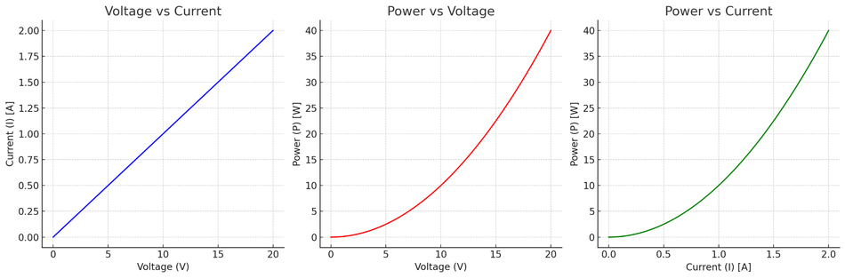
Ohm’s law states that voltage equals current times resistance (V = I·R), with power calculated as P = I²·R or P = V²/R.
Fixed, variable, and sensitive resistors vary in design and use, including film, carbon, and wire-wound for general circuits; potentiometers and rheostats for adjustable resistance; and thermistors, light-dependent resistors, and varistors for environmental response.
Resistor networks combine multiple resistors in one unit to save space, improve matching, and facilitate precise circuits like Wheatstone bridges.
Choosing a resistor requires specifying resistance, power rating, and tolerance, and considering material, packaging, temperature effects, noise, reliability, and failure modes.
Introduction
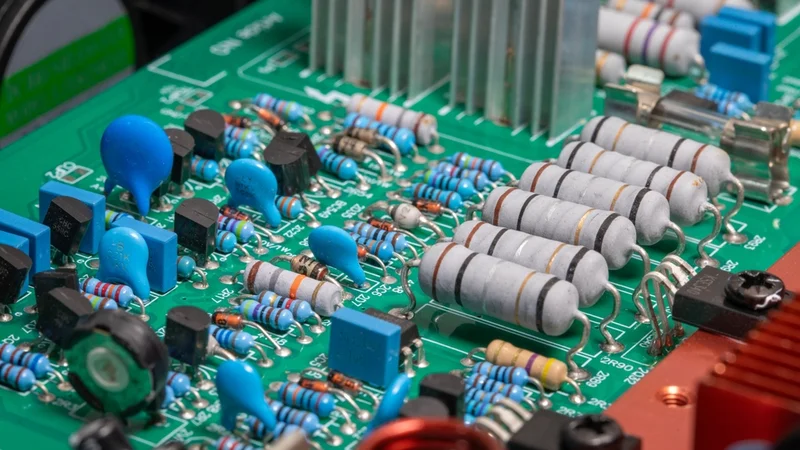
Resistors are ubiquitous. From microcontrollers and digital logic circuits to sensor interfaces and power supplies, these humble components appear in every schematic. While a resistor’s purpose is deceptively simple, i.e., opposing the flow of electric current, creating a voltage drop, and dissipating power as heat, modern electronic design relies on an array of resistor technologies, each optimized for precision, size, power dissipation, stability, or environmental robustness. For digital design and hardware engineers, understanding what a resistor in a circuit is, how it behaves under different conditions, and how to select the right type is essential for reliable products.
This article begins with the theory of resistors and Ohm’s law, then explores electrical characteristics such as resistance, tolerance, power rating, and temperature coefficient. We survey common resistor types—fixed, surface‑mount, variable, and sensitive devices—and examine network topologies from series/parallel connections to Wheatstone bridges. Practical sections show how resistors implement current limiting, pull‑ups, biasing, voltage division, and termination
Suggested Reading: PCB Components: A Comprehensive Technical Guide to Passive, Active, and Electromechanical Parts
Fundamentals of Resistors
Definition and Role
A resistor is a passive circuit element designed to impede the flow of electric charge. When current flows through a resistor, the component absorbs electrical energy and converts it to heat; the voltage drop across the resistor is proportional to the current. In an ideal linear resistor, this relationship follows Ohm’s law:
V = IR
where V is the voltage across the resistor, I is the current through it, and R is its resistance measured in ohms (Ω). The resistor, therefore, sets the ratio between voltage and current, enabling designers to control circuit behavior.
Resistivity and the physical basis
Resistance arises because electrons colliding with atoms in a material lose energy. The opposition to current is described by resistivity (ρ), a property of the material. For a conductor of length L and cross‑sectional area A, the resistance is:

Materials with low resistivity (e.g., copper) make good conductors, while high‑resistivity materials (e.g., carbon, metal oxides) become resistors. Thin, long conductors produce higher resistance, which is exploited in thin‑film and wire‑wound resistors.
Power dissipation and Ohm’s law
As current flows, a resistor dissipates power as heat. Power is given by the product of current and voltage (P = IV). Substituting Ohm’s law yields alternative forms:

Excessive power leads to temperature rise and can damage the component, so each resistor has a maximum power rating.
Electrical Characteristics
Resistance and Tolerance
The nominal resistance (R) is the key specification. However, manufacturing tolerances mean the actual value varies within a range. Tolerance is expressed as a percentage of the nominal value.
Precision wire‑wound resistors can achieve tolerances as tight as ±0.005%, while film resistors typically offer ±1 % to ±5 %, and carbon composition resistors may be ±10 % or ±20 %. Designers choose tolerance based on the required accuracy and cost; matched sets for voltage dividers or networks often offer ratio tolerances to save cost compared to individually tighter tolerances.
Power Rating
The power rating indicates the maximum power the resistor can dissipate without overheating. Typical through‑hole resistors are rated 1/8 W to 1 W; larger power resistors handle tens or hundreds of watts. Exceeding the rating can lead to thermal runaway or failure.
The rating often correlates with physical size—larger packages dissipate more heat. When selecting a resistor, compute the expected dissipation and choose a component with adequate margin (often 50 % or more) to account for temperature rise and transients.
Temperature Coefficient and Stability
Resistive materials change with temperature. The temperature coefficient of resistance (TCR) is the resistance change per degree Celsius (ppm/°C). TCR values range from ±1 ppm/°C for precision foil resistors to ±6700 ppm/°C for certain thermistors. Lower TCR means better stability over temperature. When resistors operate near each other (e.g., in a network), matching TCRs is often more important than absolute TCR; matched sets ensure resistance ratios remain constant as temperature changes.
Moreover, stability describes how resistance drifts over time due to aging and environmental stress. Wire‑wound and bulk metal resistors are very stable, while composite materials show more drift. Operating within rated power and temperature improves stability.
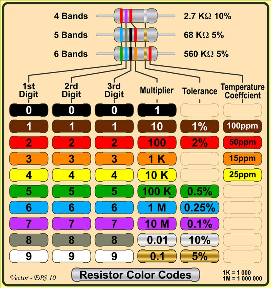
Recommended Reading: Resistor Chart: Comprehensive Guide to Resistor Values, E-Series, and Color Codes
Types of Resistors
Resistors come in various shapes and sizes, according to their applications. Here are the types of resistors.
Fixed Resistors
Most resistors have a fixed, non‑adjustable resistance. The following table summarizes the types of fixed resistors
Resistor Type | Characteristics |
Carbon composition | Made of carbon particles in a binder; inexpensive and surge-tolerant, but with high noise and poor tolerance, rarely used in new designs. |
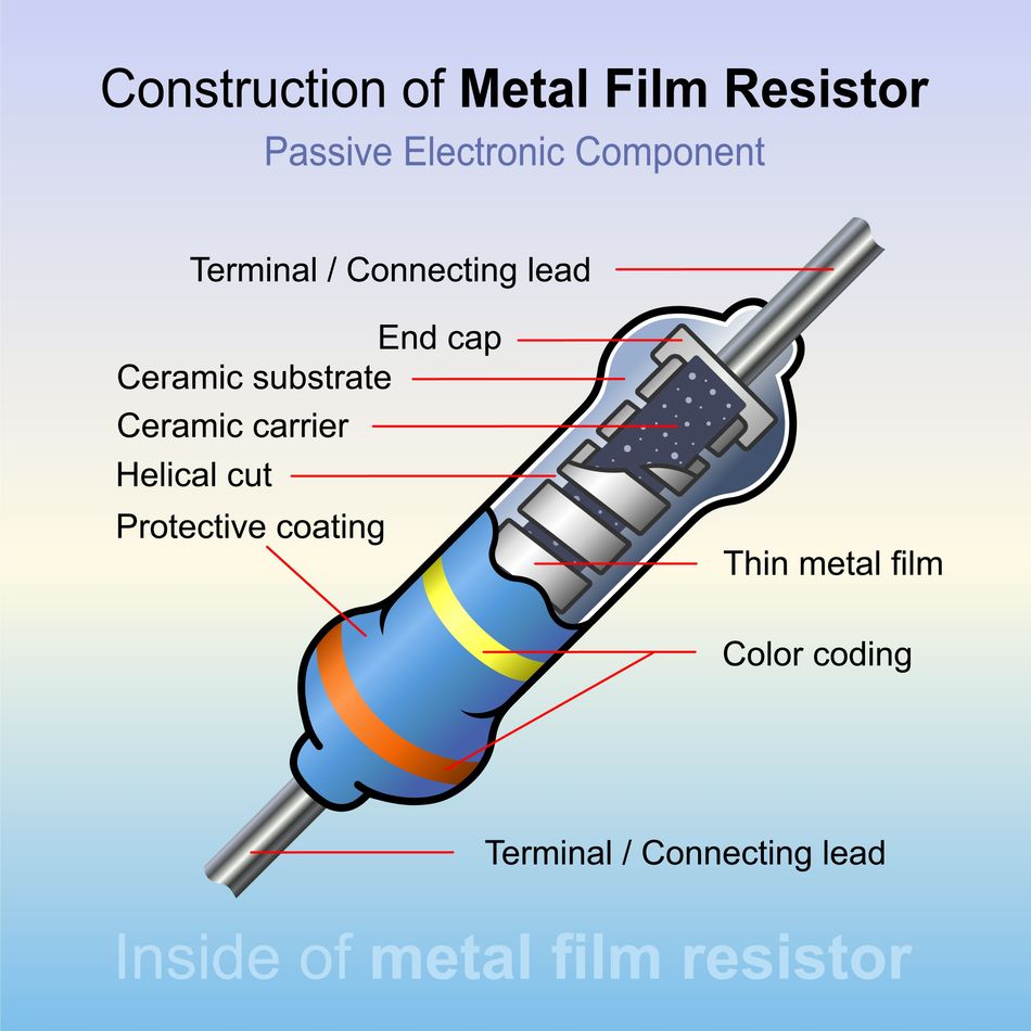
Film resistors | Resistive film on ceramic substrate; metal film and metal oxide types offer better tolerance (±1% to ±5%) and stability, widely used in general-purpose circuits. |
Wire-wound resistors | Resistive wire wound on an insulating core; handles high power, very low noise, and TCR, but inductance limits use in high-frequency circuits. |
Metal foil and bulk metal resistors | Used for extreme precision and stability with very low TCR and noise, but more expensive. |
Surface‑mount resistors (SMD)
Surface‑mount (chip) resistors pack the resistor onto a small rectangular package, allowing high‑density designs. Typical packages include:
0402 (1.0 × 0.5 mm)
0603 (1.6 × 0.8 mm)
0805, and larger.
They offer good thermal stability and low parasitic inductance. However, their small size limits power dissipation and makes manual handling difficult; they are best assembled with automated equipment. Selecting an SMD size involves balancing power rating, signal integrity, and board density.
Further Reading: SMD Resistor Sizes: A Comprehensive Guide for Engineers
Variable Resistors and Potentiometers
When a circuit requires adjustable resistance, designers use variable resistors such as potentiometers, rheostats, and trimmers. A potentiometer (pot) is a three‑terminal device with a resistive track and a movable wiper. Connecting both ends of the track and the wiper produces a voltage divider; the output varies proportionally to the wiper position.
When used as a two‑terminal variable resistor, one end of the track and the wiper form a simple rheostat. Potentiometers adjust gain, set bias points or calibrate circuits. Multi‑turn trimmers and digital potentiometers provide finer adjustment and remote control.
Sensitive Resistors
Sensitive resistors change resistance with external stimuli. They often behave non‑linearly and are used for sensing or protection.
Thermistors
Thermistors are solid‑state devices whose resistance changes steeply with temperature. Constructed from semiconductor metal oxides, they are temperature sensors and current‑limiting devices. Thermistors come in two types:
Negative temperature coefficient (NTC) – resistance decreases as temperature rises. They are widely used for temperature measurement and control. NTC thermistors are characterized by a base resistance at 25 °C and a material constant, B, that defines the resistance–temperature curve.
Positive temperature coefficient (PTC) – resistance increases with temperature. PTC thermistors provide over‑current protection and self‑resettable fuses.
Thermistors often form part of a voltage divider or Wheatstone bridge to convert temperature‑dependent resistance into a measurable voltage.
Suggested Reading: Thermistor vs Thermocouple: Which Temperature Sensor Suits Your Engineering Needs?
Light‑dependent resistors (LDR)
LDRs are photo‑resistors made of cadmium sulphide or other semiconductors. In darkness, their resistance can be tens of megaohms, while under light, it drops to a few hundred ohms.
They convert light intensity into resistance changes and are used in automatic lighting, exposure meters, and alarm circuits. LDRs form potential dividers or bridges to produce a voltage proportional to light.
Varistors
A varistor (voltage‑dependent resistor or VDR) provides over‑voltage protection. Unlike manually adjustable resistors, a varistor automatically changes its resistance in response to applied voltage. At normal voltages, it has high resistance; when a voltage surge exceeds its rated clamping voltage, its resistance drops sharply, clamping the voltage and absorbing energy.
Modern metal‑oxide varistors (MOVs) use zinc‑oxide grains to achieve fast response and high energy handling. Varistors are connected across power lines to protect equipment from lightning, switching spikes, and inductive transients.
Other specialized resistors include photoresistors (similar to LDRs), force‑sensitive resistors (FSR), magneto‑resistors, and non‑linear resistor elements such as silicon carbide varistors and polymer PTC resettable fuses.
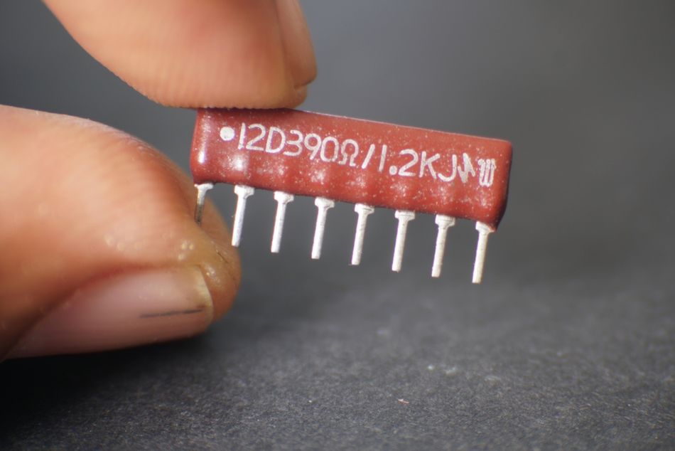
Resistor Networks and Arrays
A resistor network integrates multiple resistors into a single package. Networks can contain three to more than twenty resistors, arranged independently (isolated) or sharing a common terminal (bussed). They are used to implement pull‑ups, line termination, and gain‑setting resistors while saving board area and ensuring matched temperature tracking.
Resistor Networks and Circuit Topologies
Series and Parallel Configurations
When resistors are combined, their equivalent resistance depends on the topology.
In series, the same current flows through each resistor, and the total resistance is the sum of individual values.

The voltage drop across each resistor adds up to the supply voltage.
In parallel, resistors share the same voltage, and the reciprocal of the total resistance is the sum of reciprocals.

The equivalent resistance is always lower than the smallest branch resistance.
These relationships allow designers to achieve non‑standard values and distribute power across multiple components. For example, two 100 Ω resistors in parallel provide 50 Ω, and each resistor dissipates half the power.
Recommended Reading: Parallel vs Series Circuits: Differences, Theory, and Practical Applications
Voltage divider
A voltage divider uses two series resistors to produce a fraction of the input voltage. For resistors R1 and R2 connected in series across a voltage source, the output voltage across R2 is:

Wheatstone bridge and ratiometric measurement
The Wheatstone bridge is a network of four resistors arranged in a diamond. It consists of two voltage divider legs; a voltage source is applied across opposite corners, and the output voltage is measured between the midpoints. When the ratio of resistances in one leg equals the ratio in the other, the bridge is balanced and the output is zero. If one resistor changes (e.g., due to strain or temperature), an imbalance produces a small differential voltage proportional to the change.
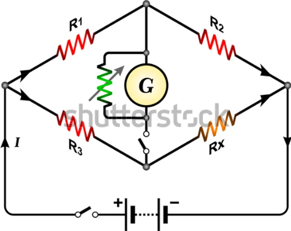
Bridges enable precise measurement of small resistance changes. In strain‑gauge circuits, the strain gauge forms one arm of the bridge; quarter‑bridge (one sensor), half‑bridge (two sensors), and full‑bridge (four sensors) configurations improve sensitivity and compensate temperature variations.
Resistor arrays in digital design
Resistor networks simplify pull‑up, pull‑down, and termination tasks. In digital buses, multiple inputs often need pull‑ups to supply voltage; using an 8‑resistor array with a common supply pin saves space. For differential signaling (e.g., RS‑485 or LVDS), termination resistors equal to the characteristic impedance (e.g., 120 Ω) at both ends of the cable prevent reflections and preserve signal integrity.
Networks with matched resistances are also used in digital‑to‑analog converters (R‑2R ladder), analog filters, and op‑amp gain‑setting circuits. Integrated resistor arrays guarantee ratio matching, which improves the accuracy and stability of these ratiometric circuits.
Practical Applications
Resistors are found virtually in every electrical and electronic application. Some basic purposes and resistor configurations remain a constant aspect of modern circuits. Here are some common applications.
Current limiting and LED protection
Limiting current through LEDs and other devices prevents damage. Connecting an LED directly to a power supply would result in excessive current and destruction. A series resistor is inserted to set the desired current. The resistor dissipates power as heat and protects the LED.
Pull‑up and pull‑down resistors
Digital inputs should never be left “floating,” because high input impedance amplifiers may pick up noise. A pull‑up resistor connects the input to the supply voltage, ensuring it reads logic high when no other signal is driving it. When a switch grounds the input, the resistor limits current and prevents a short circuit.
Typical pull‑up values are 4.7 kΩ to 10 kΩ; lower values increase current and produce stronger pull‑ups. Pull‑down resistors connect to ground to default an input to logic low.
Biasing Transistors and Amplifiers
Resistors set the bias current and operating point of transistor circuits. In a BJT amplifier, a voltage divider provides the base bias; emitter resistors stabilize bias against temperature variation; collector resistors set the voltage gain.
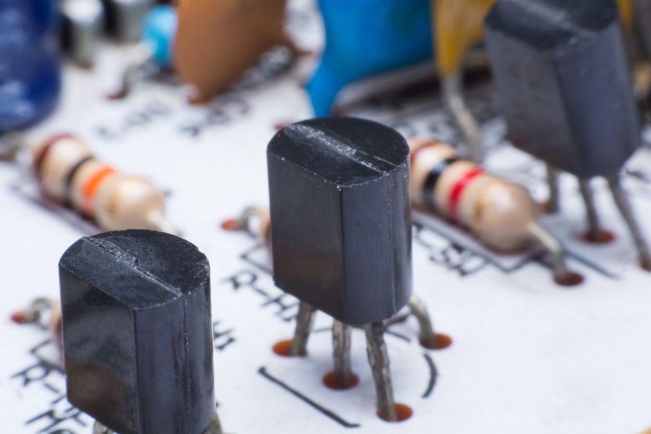
In FET circuits, gate resistors limit transient currents, and drain/source resistors set gain. Precision resistor ratios are important for stable amplifier operation.
Suggested Reading: Understanding Transistors: What They Are and How They Work
RC time constants and filters
Combining a resistor with a capacitor forms an RC circuit, which is used in different types of filter circuits. When a step voltage is applied, the capacitor charges exponentially with time constant τ = R·C; after one time constant, the capacitor charges to about 63.2 % of the supply voltage, and after five time constants, it is essentially fully charged.
RC time constants determine delays, oscillator frequencies, and filter cut‑off frequencies. Designers choose resistor and capacitor values to achieve the desired time behaviour.
Voltage and current sensing
Low‑value resistors (shunt resistors) placed in series with a load convert current into a measurable voltage via Ohm’s law. For accurate sensing, the resistor must have low resistance, tight tolerance, and low TCR. Four‑terminal (Kelvin) connections eliminate measurement error due to lead resistance.
Termination and signal integrity
In high‑speed digital communications (e.g., LVDS, RS‑485), transmission lines behave like distributed impedances. A termination resistor equal to the line’s characteristic impedance placed at the far end absorbs energy and prevents reflections. For RS‑485 networks, 120 Ω resistors are placed at both ends of the bus. Without proper termination, reflected waves distort signal edges and degrade noise margins, especially at high frequencies.
Sensor interfaces and Wheatstone bridges
As discussed in Section 4.3, Wheatstone bridges convert small resistance changes to voltage. Strain gauges, pressure transducers, and thermistors employ bridge circuits for ratiometric measurement. For example, placing a thermistor in one arm and fixed resistors in the others creates a temperature‑to‑voltage converter. Light sensors (LDRs) and potentiometers can be integrated into a bridge for improved sensitivity and drift compensation.
Suggested Reading: How to Wire a Potentiometer: A Comprehensive Guide for Engineers
Resistor Arrays for digital logic and analog front‑ends
Resistor arrays provide multiple identical resistors for pull‑ups, level shifting and DAC reference ladders. Because the resistors share a common substrate, their values track over temperature and aging, ensuring a stable ratio and improved matching. High‑performance analog‑to‑digital converters use integrated thin‑film resistor arrays with ±5 ppm/°C tracking and ±0.05 % ratio tolerance.
Resistor Selection Considerations
Selecting a resistor involves more than just its nominal value. For a reliable circuit, it's crucial to understand how resistors perform under different conditions and to use best practices during implementation.
Resistor Noise
Resistors generate electrical noise that can affect sensitive circuits. Thermal noise is a small, unavoidable amount of noise related to the resistor's value and temperature. A second type, excess noise, is generated by some materials, like carbon.
For designs that require very low noise, such as in audio or precision equipment, it's best to choose quiet resistor types like metal film or wire-wound.
Common Failure Modes
Resistors most often fail by becoming an open circuit (a disconnection) or by having their resistance value drift. Short circuits are very rare. The most common causes of failure are:
Overload: Applying more power than the resistor is rated for causes it to overheat and fail.
Environmental Stress: Exposure to high heat, humidity, or corrosive atmospheres can degrade the resistor's internal materials over time.
Mechanical Stress: Physical force or vibration can crack the resistor or break its connections.
Advanced Implementation Techniques
Beyond basic selection, these advanced techniques can improve a circuit's performance and reliability:
Resistor Networks: These packages contain multiple resistors and are useful for saving space on a circuit board, such as when you need several pull-up or pull-down resistors. For circuits that rely on highly accurate ratios, a network with matched properties is ideal.
Managing Parasitics: At high frequencies, a resistor can have unwanted inductance or capacitance. To minimize these effects, especially in radio frequency (RF) circuits, use thin-film or surface-mount resistors and avoid wire-wound types.
Kelvin Connections: For measuring current through a very low-value resistor, a special "Kelvin" connection uses separate wires to get a more accurate voltage reading by eliminating the effect of resistance in the connecting traces.
Suggested Reading: Accurate Measurements using Shunt Resistors and Current Sense Modules in High-Energy Storage Applications
Conclusion
Resistors are fundamental electronic components used to control current and voltage. While their basic function is simple, selecting the right type is crucial for a reliable design. Beyond standard fixed resistors, there are variable ones for adjustability and networks for combining multiple resistors. Key selection criteria include the resistance value, power rating, and tolerance to ensure the component operates correctly. Additionally, factors like the temperature coefficient and electrical noise must be considered for sensitive or high-precision circuits.
Engineers must also understand resistor reliability and common failure modes. Resistors can fail due to overload, environmental stress from heat or humidity, or mechanical damage, so it's important to choose components that can withstand the expected conditions.
FAQs
1. What exactly is a resistor in a circuit?
A resistor is a passive component that resists the flow of electrical current. It provides a predictable relationship between voltage and current according to Ohm’s law (V = I·R) and converts electrical energy to heat. Resistors are used to set current, divide voltage, bias active devices and provide termination and sensing.
2. How do series and parallel resistors differ?
In series, the same current flows through all resistors, and the total resistance is the sum of the individual resistances. In parallel, all resistors share the same voltage, and the reciprocals add to give the reciprocal of the total resistance. Series connections increase resistance and divide voltage, while parallel connections decrease resistance and split current.
3. Why do we need pull‑up or pull‑down resistors in digital circuits?
Digital inputs left unconnected can float to unpredictable levels, causing erratic behavior. Pull‑up resistors connect the input to the supply voltage, ensuring a defined logic high when the input is otherwise open; pull‑down resistors connect to ground for a defined logic low. They also limit the current when switches or transistors drive the input.
4. How do I choose the correct power rating for a resistor?
Calculate the expected power dissipation using P = I²·R or P = V²/R. Then choose a resistor with a power rating significantly higher than the calculated dissipation (often 50 % margin) to handle surges and temperature rise. Consider the operating environment and grouping of components on the PCB when derating.
5. What causes resistor failure, and how can I prevent it?
Common failure modes include open circuits and resistance drift due to overload, surges, high temperature/humidity, and corrosion. Prevention involves using resistors with adequate power and voltage ratings, protecting circuits against transients with varistors or TVS diodes, operating below rated limits, and selecting materials suitable for the environment.
6. What is a Wheatstone bridge, and why is it used?
A Wheatstone bridge is a network of four resistors arranged in a diamond. When the ratio of resistances in one leg matches the ratio in the other leg, the bridge is balanced and produces zero differential output. Small changes in one resistor unbalance the bridge, generating a voltage proportional to the change. Wheatstone bridges are used for precise measurement of strain, temperature, and other physical parameters.
References
RS Components. What is a resistor and how do resistors work?
au.rs-online.comElectronics Tutorials. Resistor types and characteristics
electronics-tutorials.wsUMass Applied Electrical Engineering textbook. Ohm’s law and power formulas
openbooks.library.umass.eduNCBI StatPearls. Ohm’s Law
ncbi.nlm.nih.govSparkFun. Pull‑up resistors
learn.sparkfun.comSparkFun. Resistor power rating
learn.sparkfun.comCadence. Termination resistors for transmission lines
resources.pcb.cadence.comElectronics Tutorials. Thermistors
electronics-tutorials.wsElectronics Tutorials. Light‑dependent resistors
electronics-tutorials.wsElectronics Tutorials. Varistors
electronics-tutorials.wsTT Electronics. Should you use a resistor network?
ttelectronics.comXY Resistor. Resistor arrays: structure and advantages
xy-resistor.comRiedon. Resistor characteristics and definitions
riedon.comLumen Learning. Series and parallel resistors
courses.lumenlearning.comSparkFun. Voltage divider tutorial
learn.sparkfun.comDwyerOmega. Wheatstone bridge circuits
dwyeromega.comAkahane Electronics Industry. Resistor failure modes
akaneohm.comElectronics Notes. Standard resistor values and E‑series
electronics-notes.comPCBTok. SMD resistor sizes guide
pcbtok.com