Rectifier Diode: Revolutionizing Electrical Applications with Advanced Semiconductor Technology
This article explores the latest advancements, practical applications, and ongoing challenges in the field of rectifier diodes, offering a valuable resource for engineers seeking to elevate their knowledge and practical skills.

Last updated on 27 Nov, 2025. 15 minutes read
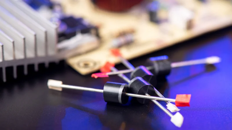
Diode, electronic component that conducts current in one direction
Key Takeaways
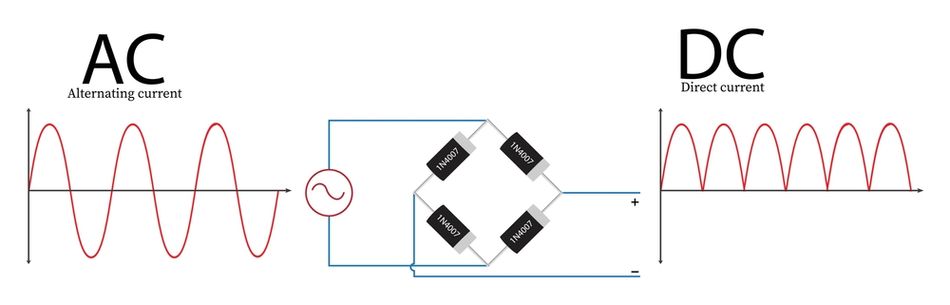
Rectifier diodes convert alternating current (AC) to direct current (DC) by allowing current to flow primarily in one direction through a p‑n junction. Their forward voltage drop is nearly constant over a broad current range.
The peak inverse voltage (PIV) defines the maximum reverse‑bias voltage a diode can withstand without breakdown. Typical rectifier diodes have PIV ratings of 50 V or higher, and high‑power versions are rated at thousands of volts.
Rectifier circuits include half‑wave, full‑wave, and bridge topologies. Half‑wave rectifiers utilise one diode, yield lower DC output, and have high ripple and low efficiency (~40.6 %). In contrast, centre‑tapped full‑wave rectifiers double the frequency of the ripple and offer higher efficiency (~81.2 %).
Types of rectifier diodes range from standard silicon diodes to fast‑recovery, Schottky and silicon‑carbide (SiC) diodes. Fast‑recovery and Schottky devices exhibit shorter reverse‑recovery times and lower forward voltage drops (≈0.3–0.5 V), making them suitable for high‑frequency power supplies.
Selecting a rectifier diode involves matching the diode’s peak reverse voltage, average forward current, forward surge current, and reverse‑recovery time to the application. Thermal management, package style, and switching frequency must also be considered.
Introduction
AC‑to‑DC conversion is at the heart of nearly all electronic systems. Whether powering digital logic circuits, charging batteries, or supplying energy to high‑power drives, designers must create rectifier circuits that efficiently and reliably convert alternating current into a stable DC voltage. Rectifier diodes are the core components of these circuits. They exploit the unidirectional conduction property of the p‑n junction to permit current flow during one half cycle of the AC waveform while blocking the opposite half. Although diodes might appear simple, understanding their characteristics and how they interact within a rectifier topology is critical for designing power supplies, chargers, inverters, motor drives, and embedded systems.
This article provides an in‑depth exploration of rectifier diodes, addressing theoretical principles, types of diodes, key electrical parameters, rectifier topologies, design considerations, implementation examples, applications, and emerging technologies. Engineers will gain practical guidance for selecting appropriate rectifier diodes and ensuring robust, high‑efficiency rectifier designs.
The Basics of Rectifier Diodes
Diode Structure and Operation
A diode is a semiconductor device formed by joining p‑type and n‑type materials, creating a p‑n junction. When forward‑biased, electrons and holes cross the junction, current flows, and the voltage drop across the diode remains nearly constant. For silicon diodes, the forward voltage is approximately 0.7 V; for germanium diodes, it is roughly 0.3 V. This nearly constant voltage drop makes diodes useful as rectifiers, clamping circuits, and voltage references.
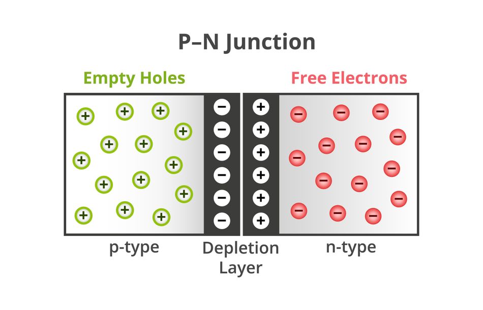
Conversely, when reverse‑biased, the depletion region widens and the diode ideally blocks current flow. The maximum reverse‑bias voltage a diode can withstand without avalanche breakdown is termed the peak inverse voltage (PIV) or reverse repetitive maximum voltage Vrrm.
Generic rectifier diodes typically have PIV ratings of at least 50 V, and high‑power rectifiers can withstand thousands of volts. Exceeding the PIV can lead to irreversible breakdown and device failure.
The physical structure influences conduction properties:
P‑N junction diode: Traditional silicon or germanium rectifier diodes use doped semiconductor junctions. They have moderate forward voltage drops (~0.7 V) and relatively long reverse‑recovery times (tens of microseconds for standard rectifiers).
Schottky diode: Formed by a metal‑to‑n‑type semiconductor junction rather than a p‑n junction, Schottky diodes exhibit very low forward voltage drops (≈0.25–0.4 V) and fast switching speeds due to reduced junction capacitance and absence of minority carrier storage.
Fast‑recovery diode: These p‑n diodes are optimised for shorter reverse‑recovery times (trr) between 200–500 ns for fast‑recovery diodes and 20–100 ns for ultra‑fast diodes.
Silicon‑carbide (SiC) Schottky diode: SiC devices combine the Schottky junction structure with a wide‑bandgap semiconductor. They have higher breakdown field strength (≈10× that of silicon), excellent thermal conductivity, low reverse‑recovery losses, and stable recovery current across temperature. So, SiC diodes operate at higher voltage and temperature with lower capacitance and improved EMI performance compared with silicon diodes.
Recommended Reading: Diode, Anode, Cathode: Unlocking the Power of Semiconductor Junctions
Electrical Characteristics and Ratings
Designers must consider several key electrical parameters when selecting a rectifier diode:
Parameter | Description | Significance |
Maximum reverse voltage | The highest permissible reverse‑bias voltage a diode can withstand without breakdown. It’s also called peak inverse voltage (PIV). | It must exceed maximum expected reverse voltage plus safety margin. |
Forward current | The average forward current the diode can conduct without thermal overload. | It should meet load requirements; high‑power rectifiers can handle tens or hundreds of amperes. |
Surge current | Peak current the diode can withstand for a short period (e.g., inrush currents or fault conditions). | Ensures the diode survives start‑up transients and fault conditions. |
Forward voltage drop | Voltage across the diode in forward conduction: about 0.7 V for silicon, 0.3 V for germanium, 0.25–0.4 V for Schottky. | Determines conduction loss (P = I × Vf). Low Vf improves efficiency in low‑voltage supplies. |
Reverse‑recovery time | Time required to cease conduction when a diode switches from forward to reverse bias. | Affects switching efficiency and EMI in high‑frequency circuits. Standard rectifiers have trr tens of microseconds, fast‑recovery diodes tens to hundreds of nanoseconds. |
Capacitance and leakage current | Junction capacitance and reverse leakage current increase with diode area and temperature. | High capacitance slows switching; high leakage reduces efficiency in low‑current applications. |
Thermal resistance and maximum junction temperature | Determine heat dissipation capability; essential for power diodes. | Thermal management using heatsinks or package selection ensures safe operation. |
What are Rectifiers?
Rectifiers are electrical devices specifically designed to convert alternating current (AC) into direct current (DC). They achieve this by utilizing components like diodes, which act as one-way routes for electricity. When AC voltage passes through a rectifier, only the portion flowing in the forward direction allowed by the diodes is permitted to pass. This results in a pulsating DC output, with the specific waveform depending on the rectifier circuit design. Rectifiers are often used in single-phase AC-to-DC conversion applications.
There are various rectifier configurations, each employing one or more diodes in specific circuit arrangements. The types of rectifiers are:
Half-Wave Rectifiers
A half‑wave rectifier uses a single diode to pass only one half of the AC waveform. During the positive half‑cycle, the diode conducts and current flows through the load; during the negative half‑cycle, the diode blocks current, and the load voltage falls to zero. This produces a pulsating DC output containing large amounts of AC ripple and uses only half of the input power.

The average output (DC) voltage Vdcof a half‑wave rectifier supplied with peak voltage Vm is:

It corresponds to 0.45 times the RMS input voltage. Because only half of each cycle contributes power, the rectification efficiency is low (40.6 %) and the ripple factor (ratio of AC component to DC component) is 1.21.
While half‑wave rectifiers are simple and low‑cost, they are rarely used for high‑power supplies because of their poor efficiency, high ripple and poor transformer utilisation. However, they remain relevant for signal demodulation, low‑current detection, and simple test circuits.
Full-Wave Rectifiers
A full-wave rectifier offers a more efficient and smoother approach to converting alternating current (AC) into direct current (DC). It uses both halves of the input waveform, producing a higher DC output and lower ripple compared to a half‑wave rectifier. This results in a rectified DC output with significantly less ripple.
The average (DC) output voltage of an ideal full‑wave rectifier is

There are two primary types of full-wave rectifier circuits:
Diode Bridge Rectifier: Uses four diodes arranged in a bridge configuration to allow both halves of the AC input to be used. Its essential characteristics include:
No centre tap required – a standard transformer suffices.
Lower PIV requirement per diode (Vm) – each non‑conducting diode sees only the peak voltage across half the secondary winding.
Better transformer utilisation – the entire secondary winding carries current in both half‑cycles.
Higher DC output – identical to the centre‑tapped case minus two diode drops (≈1.4 V total) since current flows through two diodes in series per half‑cycle.
Center-Tapped Rectifier: Uses two diodes and a center-tapped transformer, dividing the secondary winding of the transformer into two equal voltages which are then rectified by the two diodes.
Bridge rectifier circuits are the preferred choice for most applications requiring DC power due to their efficiency and superior output characteristics. Diode rectifiers are vital components in power supplies, battery chargers, DC motors, and various electronic devices that rely on a smooth and reliable DC voltage.
Recommended Reading: N-Type Vs P-Type: Difference Between P-Type and N-Type Semiconductors
Filtering and Regulation
Regardless of rectifier topology, the output is a pulsating DC waveform containing a DC component and AC ripple at a frequency equal to twice the AC input frequency for full‑wave rectifiers. Common filtering techniques include:
Capacitive filtering – A capacitor across the load stores charge and releases it during the non‑conducting interval, smoothing the waveform. The ripple factor decreases as capacitance or load resistance increases.
RC and LC filters – Combining series resistors or inductors with shunt capacitors forms single‑ or multi‑pole low‑pass filters that reduce ripple further. Inductors store energy magnetically and can supply current during non‑conduction, improving regulation.
Voltage regulation – Linear regulators or switching converters follow the rectifier to maintain a constant output voltage despite load variations. Linear regulators require adequate headroom above the regulated voltage, while switching regulators transform the rectified voltage through inductive or capacitive energy storage.
Suggested Reading: Linear vs Switching Power Supply: Understanding the Differences
Controlled Rectifiers and Active Rectification
Conventional rectifiers use uncontrolled diodes that conduct automatically when forward‑biased.
Controlled rectifiers like silicon‑controlled rectifiers (SCRs) and MOSFET synchronous rectifiers allow designers to control conduction timing and reduce losses. SCRs are widely used in medium‑ to high‑power AC motor drives and high‑voltage DC transmission systems.
Synchronous rectifiers replace diodes with MOSFETs switched on and off synchronously with the AC waveform. Because MOSFETs have lower on‑resistance than diode forward voltage, synchronous rectifiers achieve higher efficiency in low‑voltage, high‑current applications.
Suggested Reading: MOSFET Symbol: Theory, Practical Usage and Future Trends
Types of Rectifier Diodes
Rectifier diodes can be categorized into several types based on their operational characteristics and applications, each offering unique benefits suited for specific electronic functions:
Standard Silicon Rectifier Diodes
Standard silicon rectifier diodes (e.g., 1N4001–1N4007 series) are designed for low‑frequency rectification (<3 kHz). They offer moderate forward voltage drop (~0.7 V) and relatively long reverse‑recovery times (tens of microseconds).. These diodes are inexpensive and widely used in linear power supplies, battery chargers, and household appliances.
Key characteristics:
Forward current: up to 1 A or more, depending on series.
Reverse voltage: 50–1000 V across series.
Applications: Low‑frequency power rectification, AC adapters, small‑power supplies.
Fast‑Recovery Diodes (FRD/URD)
For switching power supplies and high‑frequency circuits, the reverse‑recovery time of standard diodes is too long, causing energy loss and electromagnetic interference.
Fast‑recovery diodes (FRDs) are engineered with shorter carrier lifetime to achieve trr between 200–500 ns.
Ultra‑fast recovery diodes (URDs) push trr down to 20–100 ns. These diodes operate efficiently at frequencies of tens to hundreds of kilohertz and are commonly used in switching regulators, inverters and snubber networks.
Key characteristics:
Forward voltage: 0.8–1.2 V (slightly higher than standard diodes due to lifetime control).
Reverse voltage: Typically 200–1000 V.
Applications: High‑frequency AC–DC converters, flyback transformers, snubber circuits, PFC front‑ends.
Schottky Barrier Diodes
Schottky diodes use a metal–semiconductor junction instead of a p‑n junction. The majority‑carrier conduction gives them extremely low forward voltage (≈0.25–0.4 V) and negligible reverse‑recovery time. However, their reverse voltage rating is typically limited to 30–150 V, and leakage current increases with temperature.
These properties make them ideal for low‑voltage, high‑current switching converters and frequency rectification up to tens of MHz.
Key characteristics:
Forward voltage: 0.25–0.45 V.
Reverse voltage: 30–150 V.
Reverse‑recovery time: Essentially zero.
Applications: High‑frequency switching regulators, output rectifiers in DC‑DC converters, ORing diodes for redundant supplies, radio frequency (RF) detectors.
Let’s compare their key characteristics and typical applications:
| Type | Key Characteristics | Typical Applications |
| Standard Diodes | Low Switching Speed, High Durability | Consumer Electronics, Power Supplies |
| Fast Recovery Diodes | High Switching Speed, Low Recovery Time | RF Systems, Digital Circuits |
| Schottky Diodes | Low Forward Voltage, High-Speed Switching | Power Converters, Solar Inverters |
The performance and efficiency of these diodes are heavily influenced by their internal structure and material properties.
For example, Schottky diodes, with their unique metal-semiconductor barrier, allow for less thermal stress and more efficient operation under high-frequency conditions. This precision engineering supports innovations across both industrial and consumer electronics, enhancing the capabilities and reliability of electronic systems. These diodes can be susceptible to damage from electrostatic discharge. Proper handling practices are essential to avoid ESD damage.
Choosing Rectifier Diodes
Choosing the appropriate rectifier diode is vital for ensuring efficient and reliable operation in your AC-to-DC conversion application. Here are some key factors to consider when selecting a rectifier diode:
Peak reverse voltage (PIV): Choose a diode with Vrrm at least 20–50 % greater than the maximum line voltage to handle fluctuations and transients. For a centre‑tapped full‑wave rectifier, the PIV requirement is 2Vm; for a bridge, it is Vm.
Average and surge current: Select Ifav and Ifsm above the load current and expected inrush. High‑current applications may require diodes with welded leads or stud‑mount packages.
Forward voltage and power dissipation: Lower Vf reduces conduction losses. For low‑voltage outputs, Schottky or synchronous rectifiers are preferable.
Reverse‑recovery time: For switching frequencies above a few kilohertz, choose fast‑ or ultra‑fast recovery diodes or Schottky diodes. For high‑frequency SMPS (tens to hundreds of kilohertz), a trr of <100 ns (or zero for Schottky) minimises switching losses.
Operating temperature and thermal management: Ensure the device’s junction temperature remains below its rated maximum by providing appropriate heat‑sinking or airflow. Thermal resistance (RθA) and ambient temperature determine heat dissipation requirements.
Package and mounting: Choose through‑hole (DO‑41, DO‑201), surface‑mount (SMA, SMB, SMD) or power module packages based on assembly method, space, and heat dissipation needs. For high‑power rectification, stud‑mount or module packages with integrated heatsinks are common.
Recommended Reading: Zener Diode: A Comprehensive Guide to Its Principles and Applications
Sizing Transformers and Filters
Transformer secondary voltage: Account for diode drops and regulator headroom. For a bridge rectifier with silicon diodes, subtract ≈1.4 V (or ≈0.6 V for Schottky). In centre‑tapped rectifiers, each half secondary sees one diode drop (≈0.7 V).
Suggested Reading: How to Make a Transformer: Engineering Principles and Best Practices
Capacitor selection: Choose capacitance to meet ripple voltage requirements using C ≈ I_L/(2fV_r). Use low‑ESR capacitors for high‑ripple current; consider paralleling capacitors for high‑current supplies.
Inductor design: For LC filters and switching converters, select inductors with appropriate saturation current, DC resistance, and core material (ferrite for high frequency). Inductor ripple current and voltage ripple interplay with diode recovery characteristics.
Safety and EMI Considerations for Rectifier Diodes
Surge suppression: Use surge suppressors (varistors or TVS diodes) across the rectifier input to protect against voltage spikes. Add snubber circuits across diodes or transformer windings to dampen high‑frequency transients caused by diode reverse recovery.
Electromagnetic interference (EMI): Fast recovery and SiC diodes produce less reverse‑recovery current and thus less high‑frequency noise. Additional EMI filters may be necessary to meet regulatory standards.
Isolation and protection: Provide adequate creepage distances and insulation in high‑voltage rectifiers. Consider using fuses or thermistors for over‑current and inrush protection
Latest Advancements in Rectifier Diode Technology
Enhanced Efficiency and Power Handling
Recent advancements in rectifier diode technology have significantly boosted their efficiency and power handling capabilities. These enhancements are critical for the performance of electronic devices, driven by both innovative design modifications and the introduction of new semiconductor materials. The collective impact of these changes has set new performance standards for diodes, particularly in high-power applications.
Increased Power Density: Modern diodes can handle higher power levels within smaller footprints. This is crucial in portable electronic devices where space is at a premium, enabling more powerful applications without increasing device size.
Reduced Heat Generation: Due to advancements in diode design, heat production during operation has been minimized. This reduction in heat generation extends the lifespan of electronic devices and reduces the need for complex cooling systems, making devices more durable and energy-efficient.
Improved Switching Speed: The use of materials with higher electron mobility has led to faster switching speeds. This reduction in energy loss during state changes is particularly beneficial in applications requiring high-frequency switching, such as in telecommunications and automotive electronics.
Two materials, in particular, have revolutionized diode performance:
Silicon Carbide (SiC): SiC stands out for its high thermal conductivity and electrical breakdown resistance, allowing diodes to operate at higher voltages and temperatures. These properties make SiC ideal for high-power applications like electric vehicles and industrial power systems, where efficiency and durability are paramount.
Gallium Nitride (GaN): GaN features a high electron mobility that facilitates faster switching and lower power loss. Its efficiency is particularly valuable in high-frequency applications, including RF and microwave communications, where reducing power loss is critical for maintaining signal integrity and system performance.
The integration of SiC and GaN into diode manufacturing not only enhances the intrinsic properties of rectifier diodes but also contributes to the development of more energy-efficient electronic systems. These materials are pushing the boundaries of what's possible in power electronics, enabling further advancements in technology while improving cost-effectiveness.
Miniaturization and Integration
Advancements in materials science have played a pivotal role in the miniaturization of rectifier diodes. These latest developments have been crucial in meeting the demands for smaller, more efficient, and more integrated electronic circuits (ICS). The development of ultra-compact, high-efficiency materials has enabled diodes to be embedded in microchips used in smartphones and wearable technology, where space is at a premium.

The integration of rectifier diodes with other semiconductor devices has revolutionized compact electronic designs. This synergy allows for enhanced functionality within smaller packages, essential in devices like modern medical implants and advanced automotive sensors. In these applications, efficiency, and size directly impact performance and user experience.
Nanotechnology has been instrumental in pushing the boundaries of miniaturization further. Techniques such as atomic layer deposition and electron beam lithography have enabled the precise manipulation of materials at the nanoscale. [5] This leads to diodes that are not only compact but also perform better in terms of speed and energy efficiency. While these methods present challenges, including complex manufacturing processes and higher production costs, the benefits are substantial. They include significant reductions in energy consumption and heat generation, critical for the longevity and reliability of integrated circuits in high-performance computing environments.
Practical Challenges and Considerations
Enhanced Efficiency and Power Handling
Recent advancements in rectifier diode technology have led to significant improvements in both efficiency and power handling capabilities. These are crucial for the reliability and performance of modern electronic devices. These enhancements, stemming from both architectural innovations and breakthroughs in material science, set new benchmarks for diode functionality.
The introduction of materials like Silicon Carbide (SiC) and Gallium Nitride (GaN) has been instrumental in these advancements. SiC diodes are particularly valued for their superior high-temperature and high-voltage performance compared to standard silicon diodes, making them ideal for high-power applications such as automotive or industrial power systems. The high bandgap of SiC allows it to maintain operational stability under extreme conditions, thus significantly reducing failure rates and improving device longevity.
GaN diodes stand out for their efficiency and faster switching capabilities, which are essential for high-frequency applications like RF and microwave communications. The high electron mobility in GaN translates to lower energy losses and superior performance in environments where rapid switching is required. This makes GaN diodes particularly effective in advanced telecommunications infrastructure and satellite communications, where their impact on reducing latency and boosting signal integrity can be profound.
Standardization and Compatibility Issues
Standardization is critical in the electronics industry, ensuring that rectifier diodes and other components are interoperable across various systems and devices worldwide. This process helps maintain efficiency and reliability in electronic systems, from consumer electronics to complex industrial machinery. International standards, like those established by the IEEE and IEC, provide a framework that dictates performance, quality, and safety criteria for diodes, encompassing electrical characteristics, material specifications, and testing procedures.
Real-world implications of non-standardized components can be severe, ranging from minor operational disruptions to significant system failures. For example, a lack of standardization in components used in power supply units could lead to compatibility issues. This results in power inefficiencies or even hardware damage, illustrating the critical nature of standardized specifications.
Recommended Reading: Understanding Circuit Board Components: A Comprehensive Guide
Conclusion
This article has highlighted significant technological advances and ongoing challenges in the field of rectifier diodes, particularly the evolution and impact of materials like Silicon Carbide (SiC) and Gallium Nitride (GaN). These materials have not only enhanced the efficiency and power handling capabilities of diodes but have also necessitated updates in international standards to ensure safety and compatibility across various applications.
Frequently Asked Questions (FAQs)
1. What is the difference between a rectifier diode and a signal diode?
Signal diodes (e.g., 1N4148) are designed for small currents and fast switching in logic and RF circuits. Rectifier diodes handle larger currents and voltages; they have higher forward current ratings and are optimised for power conversion rather than high‑speed switching.
2. Why is the forward voltage drop of a diode nearly constant?
When a diode is forward‑biased, carriers overcome the potential barrier in the depletion region. The voltage needed to initiate conduction depends on the semiconductor bandgap and doping; once conduction starts, incremental increases in current cause minimal changes in voltage, resulting in a nearly constant forward voltage (≈0.7 V for silicon).
3. What happens if the peak inverse voltage (PIV) of a diode is exceeded?
Exceeding the PIV causes avalanche breakdown. The depletion region cannot block the reverse voltage, leading to large reverse current that can permanently damage or destroy the diode. Designers should choose diodes with PIV ratings at least 20–50 % higher than the maximum reverse voltage.
4. How does reverse‑recovery time affect switching converters?
In switching converters, diodes repeatedly switch between conduction and blocking. Reverse‑recovery time (t_rr) is the period required for stored charge to recombine and cease conduction when the diode is reverse‑biased. Long t_rr causes current spikes, heating and EMI; using fast‑recovery or Schottky diodes with short t_rr minimises these losses.
5. Why are Schottky and SiC diodes preferred in low‑voltage, high‑current applications?
Schottky diodes have very low forward voltage drops (≈0.25–0.4 V) and negligible reverse‑recovery time, reducing conduction and switching losses. SiC diodes extend these benefits to higher voltage ratings with superior thermal performance and low recovery losses. Hence they improve efficiency in power supplies, solar inverters, automotive electronics and other high‑current systems.
6. Can diodes be paralleled to increase current capacity?
Paralleling diodes can increase current capability, but mismatches in forward voltage and temperature coefficients may cause uneven current sharing. SiC diodes have a positive temperature coefficient of forward voltage, which encourages current sharing and makes paralleling safer. Alternatively, using a bridge module or controlled rectifiers ensures balanced current.
7. What are the key considerations when designing a rectifier for a high‑frequency SMPS?
High‑frequency switching requires diodes with low reverse‑recovery time; fast‑recovery or Schottky diodes are essential. Designers must also account for increased switching losses, EMI, and snubber networks to suppress transients. Selecting low‑ESR capacitors and appropriate inductors ensures stable operation. For very low output voltages, synchronous rectification using MOSFETs may offer superior efficiency.
References
[1] All About Circuits, AllAboutCircuits. Available: https://www.allaboutcircuits.com/.
[2] Efficiency Wins, Nexperia. Available: https://efficiencywins.nexperia.com/.
[3] UTMEL Electronics, UTMEL. Available: https://www.utmel.com/.
[4] Next.gr Electronic Circuits, Next.gr. Available: https://www.next.gr/.
[5] NextPCB, NextPCB. Available: https://www.nextpcb.com/.
[6] Electronics Tutorials, Electronics-Tutorials.ws. Available: https://www.electronics-tutorials.ws/.
[7] BYJU’S Learning Platform, BYJU’S. Available: https://byjus.com/.
[8] Vedantu Learning, Vedantu. Available: https://www.vedantu.com/.
[9] Electrical4U, Electrical4U. Available: https://www.electrical4u.com