Types of Switches: Complete Engineering Guide for 2025
This technical guide details various types of switches, highlighting their configurations, functionality, emerging technologies, and selection criteria for choosing a right one for your application!

11 Jul, 2025. 22 minutes read
Types of Switches
Introduction
Switches are fundamental components in electrical and electronic systems, responsible for controlling the flow of current by opening or closing circuits. From industrial automation to consumer electronics, the right choice of switch directly impacts performance, safety, and reliability. In 2025, engineers and designers are presented with an even broader range of switch options, each designed to meet specific requirements for load capacity, environmental durability, and control logic.
This technical guide offers a comprehensive overview of the various types of switches, highlighting their construction, functionality, configurations, and advancements. If you're working with low-voltage control circuits or high-power systems, identifying the correct types of switches can optimize system efficiency and extend operational life. Let’s explore the evolving landscape of types of switches and how they fit into modern engineering solutions!
Switch Types Overview
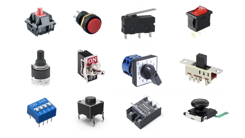
Switches are broadly categorized based on their actuation method, internal mechanism, and application. They are broadly divided into mechanical and electronic at a foundational level.
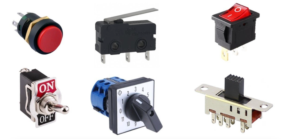
Mechanical Switches rely on physical contact and manual actuation—they open or close an electrical circuit using moving parts such as levers, buttons, or sliders. The examples include toggle switches, push button switches, rocker switches, rotary switches, and slide switches. These switches remain widely used in 2025 due to their simplicity, tactile feedback, and clear on/off states, especially in environments where user interaction is frequent.
Electronic Switches use semiconductor devices—like transistors, diodes, and MOSFETs—to manage current flow electronically. These solid-state switches have no moving parts and are activated by electrical signals, enabling high-speed operation and integration into automation and digital control systems. The common configuration is a power switch made from a MOSFET, or a transistor used to drive a mechanical relay.
Some systems combine both types—e.g., a mechanical switch triggering an electronic switch, such as a transistor or solid-state relay, to bridge microcontroller logic and high-voltage outputs.
There are some specialized and emerging switches designed for specific, often advanced, applications and represent the future of switching technology. Let’s go through these:
MEMS Switches (Micro-Electro-Mechanical Systems) offer microscopic mechanical switching in silicon for RF applications.
Optical Switches often used in fiber-optic communication, control signals using light rather than current.
Smart Switches (IoT) are integrated with wireless communication protocols like Wi-Fi, Zigbee, or Bluetooth for remote control, automation, and Industry 4.0 applications.
Gallium Nitride (GaN) and Silicon Carbide (SiC) Switches operate at higher voltages, frequencies, and temperatures, enabling high efficiency and power density in electric vehicles, renewable energy inverters, and 5G communications.
Spintronic Switches leverage the intrinsic spin of electrons in addition to their charge to represent data. This quantum mechanical property allows for the development of "instant-on" computing and non-volatile memory that requires near-zero power to maintain its state.
Meanwhile, solid-state relays (SSR) integrate electronic switches with optical isolation for efficient, contactless switching.
Recommended Reading: Understanding NPN vs PNP Transistors: A Comprehensive Guide
Switch Configurations: Poles, Throws, and Contact Types
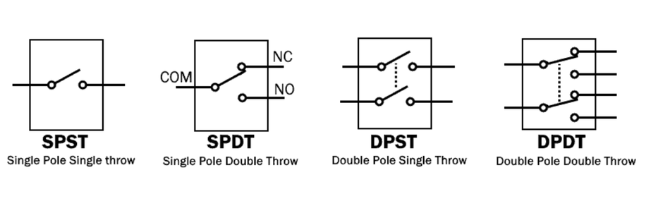
You'll often come across labels like SPST, SPDT, DPST, and DPDT, while discussing the types of switches. These refer to the internal contact configuration of a switch, specifically the number of poles and throws. Pole is essentially the number of separate circuits a switch can control. Throw is the number of output connections or positions each pole can be connected to.
Now, let’s get into basic switch configurations:
SPST (Single Pole Single Throw) is the most basic switch form: one input and one output. It functions like a basic on/off switch, ideal for simple electrical devices such as turning a light fixture on or off. SPST switches have two terminals and are used in light switches, basic automation systems, and power switches.
SPDT (Single Pole Double Throw) allows one input to connect to one of two outputs. It has three terminals and is ideal for toggling between two circuits—like switching between battery power and external power. SPDT switches are common in light control, selector switches, and joystick applications. Many SPDTs include a center-off position, making them ON-OFF-ON.
DPDT (Double Pole Double Throw) is essentially two SPDTs controlled together. It has two input poles and four output throws, supporting six terminals in total. These are commonly used to reverse polarity in DC motor control, allowing bidirectional movement, or to control two circuits simultaneously. The number of poles and throws increases circuit complexity and flexibility, but also size.
Other configurations include DPST (Double Pole Single Throw), which toggles two circuits together (e.g., live and neutral lines), and advanced forms like 3PDT or 4PDT, are used in specialized switching systems to control multiple circuit paths simultaneously. However, beyond DPDT, switches become large and are used only in specific applications due to bulk and complexity.
The actuation behavior is another critical aspect when evaluating the types of electrical switches:
Maintained vs. Momentary: Maintained (latching) switches retain their state once actuated. Toggle switches and rocker switches usually fall into this category. In contrast, momentary switches return to their default position when released—common in push button switches, doorbells, and tactile switches like keyboards.
Normally Open (NO) vs. Normally Closed (NC): These terms define a switch's off state without actuation. NO contacts are open by default and close when activated; NC contacts are closed and open when pressed. For instance, limit switch sensors in industrial machines often use NC logic to ensure safety.
Changeover Contacts (SPDT): These switches offer both NO and NC connections. The switch “changes over” from one to the other when actuated. This configuration is widely used in signal routing and electronic circuits.
Furthermore, in multi-throw switches, the sequence of connections is vital.
Make-before-break (MBB) ensures a new contact is connected before the old is disconnected, minimizing current flow interruption.
Break-before-make (BBM) breaks the first connection before making the new one—standard in slide switches and rotary switches to prevent short circuits.
If you need to switch both line and neutral in a high-current circuit, a double pole switch like DPST is necessary. If you’re just toggling power to a device, an SPST will suffice, and if you're selecting between two signal paths, SPDT is the ideal choice.
Mechanical Switches (Toggle, Rocker, Push-button, Rotary, etc.)
Mechanical switches require physical action (usually human or mechanical force) to change their state. They contain moving parts and metallic contacts that open or close an electrical circuit. Mechanical switches come in many forms, each suited to different interface and circuit requirements.

Below are their common types:
Toggle Switches
A toggle switch is operated by flipping a lever or paddle up/down or side-to-side. These are maintained switches, meaning they stay in their last position until manually toggled again. The common configurations include SPST, SPDT, and DPDT. Toggle switches are valued for their tactile feedback and clear on/off states.
They are widely used in automotive, aerospace, and instrumentation panels, as well as in power switches for tools and devices. A center-off SPDT toggle switch provides three positions (ON-OFF-ON), allowing for switches work logic in control systems. Toggle switches can handle a broad range of currents, from signal-level control to amps in power circuits.
Rocker Switches
Rocker switches function similarly to toggles but use a rocking actuator. Pressing one side down raises the other side, pivoting about a center axis. Often found on surge protectors, appliances, and light switches, they are compact and easy to operate. Like toggles, they can be SPST or DPDT, often supporting illumination or LED indicators.
Many rocker switches are rated for 15A at 120VAC, suitable for moderate-power loads. Their smooth, low-profile surface and maintained actuation make them ideal for control lighting or switching electrical devices.
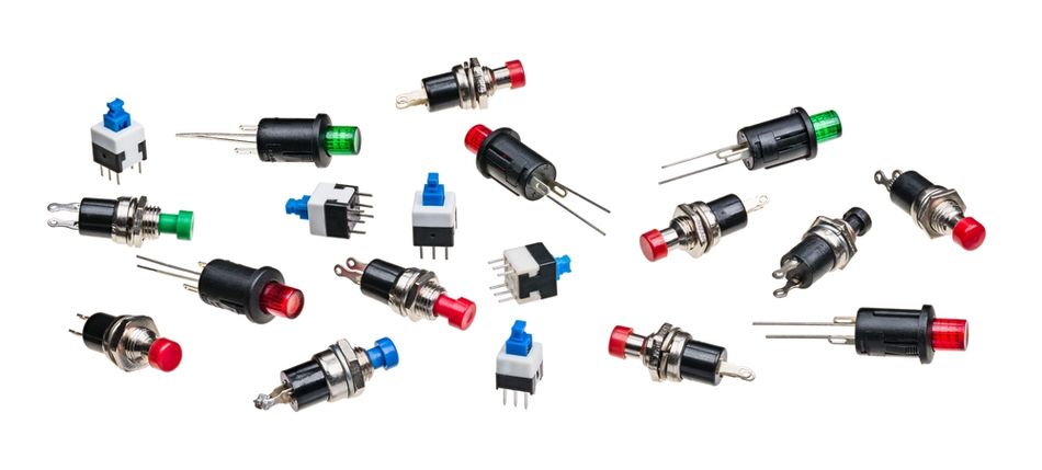
Push-Button Switches
A push-button switch is activated by pressing a plunger or button. These come in the following types:
Momentary push-buttons return to their default state when released and are often normally open (NO).
Latching push-buttons toggle their state with each press.
The common uses include keyboards, elevator controls, reset switches, and emergency stop buttons. Many push-buttons are mounted on PCBs and control logic-level signals. Tactile switches, a subset of push-buttons, are tiny, momentary types with a sharp click, used extensively in compact electronic devices.
Push-buttons may also be normally closed (NC), particularly in safety systems. These switches typically control low power directly but can drive higher loads through a transistor or relay.
Slide Switches
Slide switches use a sliding knob to open or close contacts. These are maintained switches and often SPST or SPDT. They're common in DIP switch arrays, battery-powered devices, and small gadgets. Because of their small form factor, they're used in electronic switches where energy efficiency and space are key.
Slide switches physically move a metal contact bridge over terminals and usually handle small currents (under 1A). They offer basic automation options for user configuration, especially on embedded hardware.
Rotary Switches
Rotary switches turn a shaft to cycle through multiple positions. These allow selection between many outputs, making them ideal for selector switches in test equipment, multimeters, or audio mixers. Rotary switches may support multiple poles and throws—e.g., a 4PDT rotary with 10 positions.
Rotary DIP switches are often used for address setting in networks or mode selection in embedded systems. Most rotary switches are maintained, providing clear, stepped selection with durable detents for each position.
Micro Switches (Snap-Action & Limit Switches)
Micro switches, also known as snap-action switches, actuate rapidly at a specific travel point. Internally, they often use an SPDT configuration, with NO and NC terminals. These are commonly used as limit switches to detect motion endpoints in machinery, door sensors, and arcade buttons.
They are known for long life—often millions of cycles—and quick, clean switching action. Micro switches can be actuated by a lever, roller, or plunger, and are common in automation and safety interlocks.
Other Mechanical Switches
DIP Switches: Arrays of tiny SPST slide or rocker switches, typically used on circuit boards for device configuration
Mercury Switches: Tilt-operated switches using liquid mercury, now rare due to environmental concerns.
Foot Switches: Robust push button switches actuated by foot, often used in musical instruments or industrial machines.
Reed Switches: Magnetically operated sealed switches, common in door alarms and sensor circuits.
Joystick Switches: Combine multiple switches in one interface, used in gaming or robotic control.
One notable behavior of mechanical switches is contact bounce! When metal contacts close, they often bounce before settling, producing a series of rapid, unintentional pulses lasting a few milliseconds. In power circuits, this doesn’t usually matter, but in electronic circuits, it can create false triggers. The debouncing techniques—like RC filters or software delay—are essential when interfacing with microcontrollers.
To counter non-idealities like, contact resistance, arcing, or wear and tear, high-end switches use gold-plated contacts for low signals or silver alloys for higher loads. Proper actuation force, contact materials, and wetting current help ensure switch longevity and reliability. Despite these limitations, mechanical switches are simple, intuitive, and often provide galvanic isolation. They remain the best choice for many user interfaces and power switching tasks.
Recommended Reading: How Do MOSFETs Work: Comprehensive Technical Guide for Engineers (2025)
Electronic Switches (Transistors, MOSFETs, and Relays)
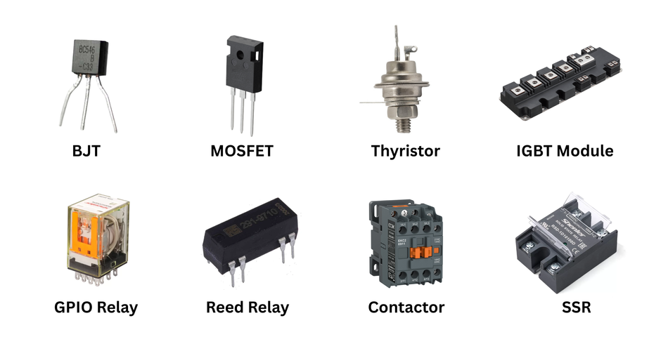
Electronic switches use semiconductor devices to perform the switching function, instead of physical moving contacts. These include transistors (BJTs, MOSFETs), thyristors (SCR, triac), and other integrated electronic switches. Their operation is based on semiconductor junctions and voltage or current actuation, making them faster, more compact, and longer-lasting than mechanical switches.
Transistor Switches (BJTs and MOSFETs)
Transistors are the most common form of electronic switches. When operated in switching mode, a transistor acts like a solid-state replacement for a mechanical on/off switch.
A BJT (Bipolar Junction Transistor) is a current-driven device. When sufficient base current is applied, it enters saturation, allowing current to flow from the collector to emitter, behaving like a closed switch. When the base current is removed, it enters cut-off, stopping current flow.
In contrast, a MOSFET (Metal-Oxide-Semiconductor Field-Effect Transistor) is a voltage-driven switch: apply a voltage to its gate to allow current to flow between drain and source (for an enhancement-mode MOSFET).
MOSFETs are very popular as electronic switches because they can handle high currents with very low on-resistance, especially power MOSFETs. They are favored in switching applications due to Low Rds(on), fast switching times, minimal gate current, high current and voltage handling. For example, a logic-level N-channel MOSFET like the IRLZ44N can be driven directly by a 5V microcontroller and can handle over 30A with a very low voltage drop.
BJTs are still useful in simple, low-cost applications where load current is modest, like switching LEDs, relay coils, or small motors. However, MOSFETs have largely replaced BJTs in high-efficiency power switches due to their superior switching speed and efficiency.
IGBTs (Insulated Gate Bipolar Transistors): For very high power and voltage applications, engineers turn to IGBTs (Insulated Gate Bipolar Transistors). IGBTs combine the easy gate drive of MOSFETs with the high-current handling of BJTs, making them ideal for motor drives, solid-state relays, and power inverters. Though slower than MOSFETs, they handle high voltages more efficiently.
Thyristors: Thyristors, such as SCRs and TRIACs, are used in AC power control. An SCR latches on when triggered and conducts until the current drops below a threshold. A TRIAC can conduct in both directions and is commonly used in dimmer switches, fan speed controllers, and AC motor drives. These devices are critical in electronic switches for AC applications.
Unlike mechanical switches, transistors do not offer galvanic isolation, meaning the control and load circuits share a common reference. In such cases, optocouplers or mechanical relays may be needed. Additionally, fast switching can introduce EMI, requiring careful layout and filtering.
For example, using a 2N3904 NPN transistor to switch a relay coil from a microcontroller illustrates how small control signals can drive larger loads. A flyback diode is essential across the coil to protect the transistor from inductive kickback.
In summary, transistors—especially MOSFETs—have become the most common type of electronic switch, enabling precise, fast, and reliable control in countless applications.
Electromechanical Relays
A relay is an electrically actuated switch: it uses an electromagnetic coil to pull mechanical contacts open or closed. While the output side of a relay is mechanical, we classify it under electronic switches since it is actuated by an electrical control signal (the coil current) rather than by a person flipping a lever. Relays come in various types and sizes:
General-purpose Relays: The most common form is the general-purpose relay—typically housed in a rectangular case, often called an “ice cube” relay. These relays may use a 12V coil to drive contacts capable of switching 10A at 250VAC. They often have SPDT or DPDT contact configurations, also known as Form C contacts (with common, NO, and NC terminals). When the coil is energized, it generates a magnetic field that pulls the movable armature, changing the contact state. Removing power deactivates the magnetic field, and a spring restores the contacts to their default position. This mechanism mimics a toggle switch function triggered by electrical signals, not manual actuation.
Power Relays and Contactors: For higher power (tens to hundreds of amps, such as in industrial power control or automotive starter circuits), relays are built bigger and are often called contactors. They might have multiple poles and are designed to handle heavy arcing with arc blowouts, etc. These operate on the same principle but are physically larger to handle large currents. For instance, an automotive starter relay (solenoid) or a 3-phase motor contactor.
Reed Relays: Reed relays use thin ferromagnetic metal reeds sealed in a glass tube. When a coil surrounding the tube is energized, the reeds are pulled together, closing the contact. Reed relays are compact, fast, and require little power, making them ideal for high-speed switching in logic circuits or sensor interfaces. A similar device, the reed switch, is magnetically actuated and commonly used in security systems (e.g., door/window sensors). These are SPST or SPDT, often rated for small currents and low voltage.
Relays have excellent on-state performance—contact resistance is often below 0.05 ohms, resulting in minimal voltage drop. They can switch AC or DC, handle high voltages, and are tolerant of load transients that might damage MOSFETs or BJTs. However, relays are slower than solid-state switches, taking 5–20 milliseconds to operate. They also wear over time: contact erosion from arcing, mechanical fatigue, and moving parts limit their lifespan to 100,000 – 1,000,000 operations under rated load.
Other limitations include:
Coil Power Consumption: A 12V relay might draw 30–100 mA continuously.
Contact Bounce: Like mechanical switches, relays exhibit bouncing on contact closure.
Audible Clicking: May be undesirable in noise-sensitive applications.
Size and Throw Limitation: Most relays are SPST, SPDT, or DPDT; not ideal for high-throw configurations.
Despite these trade-offs, electromechanical relays remain indispensable where isolation, reliability, and fail-open safety behavior are required—such as in automotive, industrial control, and home automation.
Recommended Reading: The Optoelectronics Behind Factory Automation
Solid-State Relays (SSR)
A Solid-State Relay (SSR) is an electronic switching device that replicates the function of a mechanical relay, but without any moving parts. Instead, it uses semiconductors to perform switching, providing silent, high-speed operation and virtually infinite mechanical life. SSRs are ideal for applications requiring fast, frequent, or vibration-resistant switching.
SSR typically consists of an optocoupler input for electrical isolation, usually made of an LED and a phototransistor or photodiode. It also includes a semiconductor switching element, such as a MOSFET, triac, or transistor.
For example, in AC switching, a common SSR design uses an LED to trigger a phototriac, which then activates the main triac to control the AC load. For DC SSRs, back-to-back MOSFETs or transistor pairs are used to control current flow.
Below are the advantages of SSRs:
Extremely Long Life: With no contacts to degrade, SSRs can exceed 100 million operations. Their reliability is limited only by internal semiconductor wear or LED aging, making them ideal for industrial automation or IoT systems.
Fast Switching: SSRs switch in milliseconds or even microseconds. This speed is critical in PWM control or high-speed switching where mechanical switches would wear out quickly.
No Contact Bounce or Arcing: Since SSRs are purely electronic, there’s no contact bounce, physical contact, or arcing, reducing EMI and ensuring cleaner switching.
Silent Operation: No clicking sound makes them suitable for consumer electronics, medical devices, or sound-sensitive environments.
Vibration Resistance: With no moving elements, SSRs perform reliably in shock and vibration-prone environments like automotive or industrial settings.
Despite their benefits, SSRs have some important trade-offs:
On-State Voltage Drop and Heat: SSRs have a voltage drop across their Rds(on) (MOSFET) or forward voltage (triac), leading to power dissipation. For instance, at 10A with 0.1 Ω, the SSR would dissipate 10W, requiring heat sinking.
Off-State Leakage: Unlike mechanical switches that physically separate contacts, SSRs leak small current even when "off." AC SSRs using triacs can leak a few milliamps; DC versions leak less but still aren't true "open circuits."
Higher Cost: SSRs generally cost more per pole than electromechanical relays, especially at higher current or voltage ratings.
Limited Configurations: Most SSRs are SPST (Form A). For SPDT functionality, you often need to use two SSRs with added logic to prevent simultaneous conduction.
Thermal and Load Sensitivity: SSRs may require derating at high temperatures. Some AC SSRs may not turn off properly if load current is too low or capacitive.
Failure Mode: SSRs often fail closed (shorted), which can be dangerous in safety-critical systems. In contrast, mechanical relays more commonly fail open.
SSRs are essential in modern electronic switches, particularly where long life, fast response, and silent operation are priorities. While they require more careful design considerations, they continue to replace mechanical relays in many high-speed and low-noise applications.
Recommended Reading: What is a Semiconductor? A Comprehensive Guide to Engineering Principles and Applications
Advanced and Emerging Switch Technologies (MEMS, Optical, etc.)
Let’s explore some of the most notable advancements shaping the future of electronic switches in 2025.
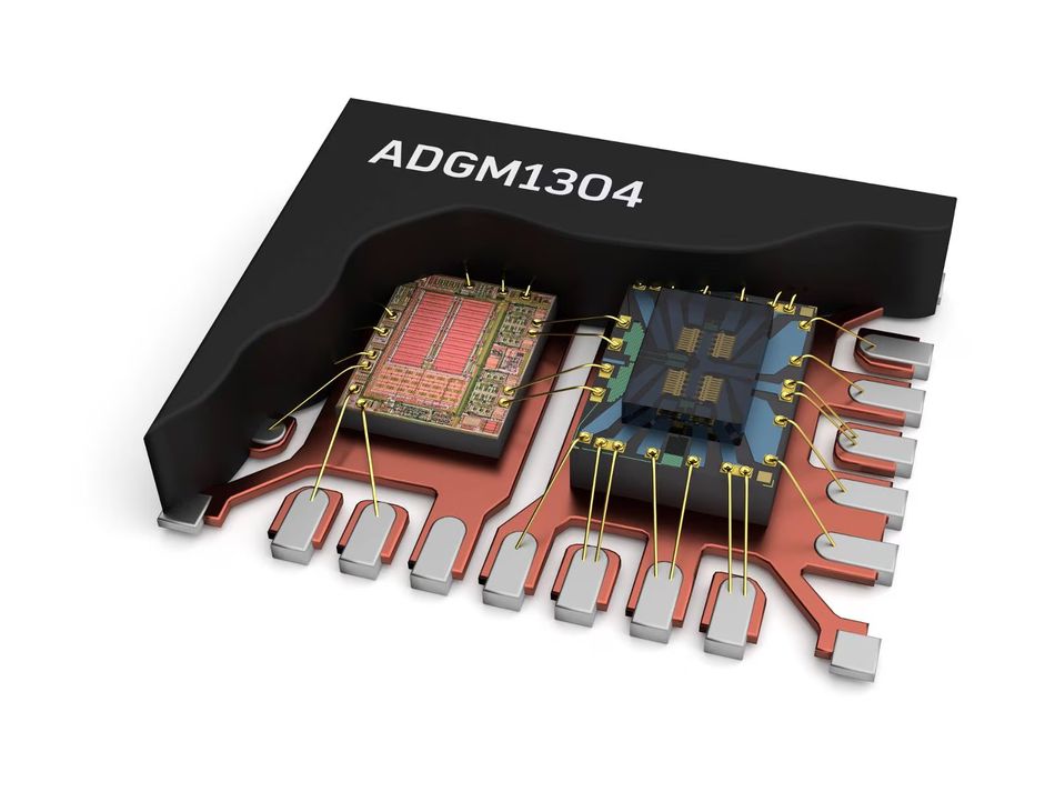
MEMS Switches (Micro-Electro-Mechanical Systems)
MEMS switches are microscopic mechanical switches fabricated using semiconductor manufacturing techniques. Internally, they include tiny moveable beams or cantilevers that open or close electrical circuits under electrostatic or thermal actuation. Though mechanical in nature, their small size, high reliability, and speed place them among the most promising solid-state alternatives for advanced applications.
Key Advantages:
RF and High-Frequency Performance: MEMS switches have low insertion loss and high isolation, making them ideal for frequencies into the tens of GHz. Unlike transistor-based switches, which introduce parasitic capacitance and degrade high-frequency signals, MEMS contacts offer nearly ideal switching for RF circuits.
Low Power Consumption: MEMS actuation often requires minimal current—just enough to charge a capacitor. While they may need a higher actuation voltage (30–80V), this is easily handled by internal charge pumps, making MEMS attractive for battery-powered and energy-efficient designs.
Long Lifetime: Due to their minuscule mass and carefully engineered contacts, MEMS switches can exceed a billion switching cycles, far outperforming mechanical switches.
Compact Size: MEMS technology allows for ultra-small switch integration, enabling RF switching matrices and phased-array antennas in tight form factors, particularly for 5G/6G, aerospace, and defense applications.
The challenges include reliability issues like stiction, shock sensitivity, and packaging complexity. However, as of 2025, manufacturers like Analog Devices are producing commercially viable MEMS switches for high-frequency and mission-critical systems.
MEMS switches may come in SPST or shunt forms and can be either ohmic (metal-to-metal contact) or capacitive, depending on whether DC conduction is required. Capacitive MEMS switches are especially effective in high-frequency applications where only signal coupling is needed.
Optical Switches
The term optical switch encompasses various devices that use light to control or route signals. In electronics, they typically fall into two categories:
Fiber-Optic Routing Switches: Used in telecom and data centers, these route light signals directly in fiber networks. They may use MEMS mirrors, thermo-optic effects, or liquid crystals to direct paths without converting to electrical signals. These are essential in large-scale optical communication but are not common in embedded or PCB-level electronics.
Optically Isolated Switches (PhotoMOS/Optocouplers): These are much more relevant in electronics. A PhotoMOS relay or optocoupler uses an internal LED and photo-sensitive MOSFET or transistor to create an isolated solid-state switch. They are often used in sensor interfaces, test equipment, and signal switching.
The benefits include zero-contact bounce, silent operation, and high isolation between control and load. On the other hand, limitations include on-resistance (often tens of ohms), limiting them to low-current applications (e.g., 100 mA to a few amps).
Optical limit switches and photo-interruptors, where an object blocks an IR beam, are also widely used in place of mechanical switches for position sensing in automation and consumer electronics.
Other Emerging Switch Tech
Solid-State Circuit Breakers & Hybrid Contactors: These combine MOSFETs, IGBTs, or GaN/SiC transistors to form high-speed breakers and contactor replacements in power systems like EVs and industrial panels. They disconnect circuits in microseconds, handle inrush currents, and prevent arcing. Some use hybrid configurations, combining a mechanical relay with a parallel solid-state path for improved longevity and control.
Magnetoresistive & Hall-Effect Switches: These non-contact switches output digital signals in response to magnetic fields. Common in automotive, consumer electronics, and IoT, they replace limit switches and reed switches in speed sensing, door detection, and position feedback. Hall-effect switches are fully solid-state, fast, and highly reliable, making them ideal for applications where physical contact is undesirable.
Quantum and Spintronic Switches: While not yet commercially viable for general design, research into quantum switches, spin-based transistors, and terahertz switching is ongoing. These promise ultra-low power consumption and speed far beyond what conventional semiconductors allow. Although not part of today’s circuit designer’s toolbox, they represent the future of electronic switches at the quantum scale.
Software-Defined & IoT-Controlled Switches: Many modern switches are no longer physical. In smart home systems, a “light switch” may simply send a wireless command to a controller that then operates a relay, MOSFET, or smart switch. These software-defined switches are now common in building automation, HVAC systems, and remote monitoring platforms.
This evolution introduces new challenges: integration with microcontrollers, Wi-Fi/Bluetooth connectivity, cybersecurity, and cloud-based logic control. Engineers must now design with both hardware and software switching in mind.
Recommended Reading: Microcontroller vs Microprocessor: A Comprehensive Guide to Their Differences and Applications
Selection Criteria for Choosing a Switch
Choosing the right switch for an application requires evaluating several technical criteria and sometimes mechanical considerations.
Below are the key factors:
1. Voltage Rating
Every switch has a maximum voltage it can safely handle. For mechanical switches, this rating ensures the contacts can break the circuit without arcing, especially in AC systems where voltage reverses and zero-crossings help extinguish arcs. DC, by contrast, lacks these zero-crossings, making it harsher on contacts. Therefore, a switch might be rated 250 VAC but only 30 VDC.
For electronic switches, such as BJTs, MOSFETs, or SSRs, the relevant parameters are V_CEO (for BJTs), V_DS (for MOSFETs), or the output voltage rating (for SSRs). It is better to select a switch with a voltage rating comfortably above your circuit’s peak voltage. If you're switching inductive loads, account for transient voltage spikes—use snubber networks, flyback diodes, or TVS protection, or select switches rated for inductive kick.
2. Current Rating
Switches must handle both steady-state and surge currents. Many mechanical switches are rated for resistive loads only. If you're driving motors, solenoids, or transformers, check de-rated values or standards like AC1/AC3 categories used in contactors.
MOSFETs, IGBTs, and power relays must be evaluated for both continuous and pulse current handling. A MOSFET might handle 50A continuously with a proper heatsink but only allow 150A for 100 μs during inrush. Always review safe operating area (SOA) graphs in datasheets and consider thermal limits.
3. On-State Resistance and Contact Drop
Mechanical switches typically offer near-zero contact resistance (milliohms), making them efficient in high-current applications. However, contact resistance becomes relevant in low-voltage circuits or signal paths—where gold-plated contacts are preferred for reliability and low noise.
Electronic switches, on the other hand, always present a voltage drop in the on-state. For example, a solid-state relay with a 0.1 Ω R_DS(on) carrying 10 A will dissipate 10 W as heat. This power loss can demand heat sinks, ventilation, or thermal derating.
4. Switching Speed
Mechanical switches typically take several milliseconds to actuate and may suffer from contact bounce. If your design requires rapid switching, like PWM motor control or multiplexing, choose electronic switches like MOSFETs (nanosecond scale) or MEMS switches (micro- to millisecond scale).
A relay switching 86,400 times per day (once per second) could wear out in months. In such cases, a triac, IGBT, or MOSFET will offer far longer life and better control.
5. Action Type (Momentary vs Maintained)
Decide whether the switch should remain in its new state after actuation (maintained) or return automatically (momentary). For example:
Momentary push-button switches are used in keyboards, reset buttons, or doorbells.
Maintained toggle or rocker switches are used for on/off power control.
Special combinations also exist—such as a (ON)-OFF-ON toggle where one “ON” is momentary and the other maintained.
6. Environmental Considerations
Consider operating conditions:
For outdoor use, look for IP-rated enclosures (e.g., IP67 for waterproof push-buttons).
In vibration-prone environments, mechanical switches may loosen. Choose locking toggles, snap-in rockers, or solid-state switches.
For explosive atmospheres, avoid devices with arcing contacts—use SSR or intrinsically safe barriers.
For automotive or industrial applications, ensure parts meet temperature and vibration standards (e.g., -40°C to +125°C).
7. Longevity and Mechanical Endurance
Mechanical switches have limited life spans. For example:
Typical Relay: ~100,000 operations under full load.
Mechanical Keyboard Switch: 50 million presses.
SSRs: Over 100 million operations (limited mainly by semiconductor degradation).
MEMS switches: Capable of billions of cycles.
Check datasheets for both mechanical and electrical life, as they can differ significantly. It is even better to ensure your duty cycle matches the expected usage scenario.
8. Size and Form Factor
Board space and mechanical integration often dictate the switch type:
For PCB-mounted configurations, use SMD tactile, DIP, or slide switches.
For panel-mounted designs, consider mounting style, aesthetics, and user feel—a large toggle switch may convey industrial robustness, while a flush capacitive touch sensor may suit sleek consumer products.
Relays are bulkier than SSRs or FET-based switches, so compact designs may favor solid-state components.
9. Drive Requirements
Every electronic switch requires an appropriate control signal:
A MOSFET needs sufficient gate voltage—ensure it’s a logic-level device if using 3.3V logic.
An SSR may require 5V @ 10–20 mA to drive its internal LED—check if your microcontroller can source that or if you need a driver transistor.
Some PhotoMOS relays or integrated switch ICs are optimized for microamp input and may work directly from GPIO pins.
For mechanical switches, also consider tactile force and feedback—particularly important for human interfaces.
10. Isolation Requirements
When electrical isolation is necessary (e.g., switching mains from a microcontroller), your options include:
Electromechanical Relays: Provide high-voltage physical separation (often >4 kV).
SSRs with Optocouplers: Offer up to 2.5–4 kV of isolation.
Transistor Networks: Require external level shifters or isolators unless everything shares the same ground.
Isolation also helps reduce noise coupling and improve system safety.
11. Cost and Availability
Sometimes the cheapest solution is the best, especially in high-volume production. The mechanical toggle switches, rockers, and relays are widely available and cost-effective.
SSRs, MEMS, and specialized semiconductor switches can cost more, particularly for high-current models. Additionally, advanced parts may be limited to a few suppliers. Always check lead times, alternates, and supplier reliability.
12. Regulatory and Safety Standards
When switching AC mains or hazardous voltages, ensure the switch meets safety standards like UL, IEC, or CE. Design considerations include:
Creepage and clearance for PCB traces
Proper Fusing and enclosure ratings
Fail-Safe Behavior: In safety systems, a normally closed (NC) mechanical switch might be preferred so the system fails "off" if power is lost or a wire breaks.
13. Special Features and Aesthetics
Modern switches often offer value-added features:
Illuminated Switches: Combine status indication and control.
Key Switches: Offer security (e.g., for industrial mode control).
Capacitive Touch Switches: Sleek design, no moving parts.
Resettable Switches: Combine fuse and switch in one (used in power tools or chargers).
In analog circuits, analog switch ICs must be evaluated for charge injection, on-capacitance, and leakage.
Example Selection Scenario
Suppose you're designing a smart home wall switch to control 5A 230V AC lighting via Wi-Fi.
Mechanical Relay: Easy to drive, provides isolation, inexpensive. But audible clicking may be annoying, and contact wear is a concern for frequent switching.
Triac-Based SSR: Silent, reliable, compact. Handles AC well and integrates easily with zero-cross detection for soft start or dimming. However, it generates heat and may require a heatsink.
MOSFET SSR: Offers silent switching, better for DC or universal AC/DC, but more complex, costlier, and less common in off-the-shelf form.
In most smart switches, the triac SSR wins due to silent operation and simplicity, despite thermal considerations.
Future Outlook for Switch Technology
The switch technologies in use today will continue to evolve, with several clear trends emerging.

Let’s get into the detail:
Solid-State Replacing Mechanical
In automotive, industrial, and consumer applications, MOSFETs, SSRs, and high-side driver ICs are rapidly replacing mechanical relays for functions like motor and lighting control. These “smart fuses” offer fast response, diagnostic feedback, and remote control—all impossible with traditional relays. As prices fall and reliability improves, the mechanical relay may become rare outside of specialty use cases.
Wide-Bandgap Semiconductors
The rise of GaN and SiC transistors enables higher voltage and frequency switching with lower losses. This paves the way for solid-state circuit breakers, compact power modules, and even software-defined breaker panels in smart homes and factories. These devices can measure current, communicate status, and open circuits in microseconds—unlike traditional electromechanical breakers.
Smarter, Integrated Switches
Future switches will do more than just toggle power. Integrated load switches and smart contactors will include features like current sensing, thermal protection, and wear monitoring. In industrial systems, this enables predictive maintenance and reduces unexpected downtime.
MEMS and Optical Evolution
MEMS switches will gain more ground in RF, telecom, and aerospace due to their high-frequency performance and tiny size. Meanwhile, optical MEMS could enable dynamic light switching in data centers for low-latency network reconfiguration. These technologies promise reconfigurable hardware with virtually no signal loss.
Wearables, Energy Harvesting, and Flexibility
In emerging markets like wearables and medical electronics, we’ll see flexible switches made from conductive polymers or nano-materials. Some will harvest energy from touch or motion to wirelessly trigger a control signal—ideal for IoT and batteryless systems.
Quantum and Hybrid Innovations
Though still experimental, quantum switches and spintronic transistors may redefine switching in future computing hardware. On the mechanical side, hybrid relays may use electronic assist to suppress arcing and extend lifespan, offering a blend of ruggedness and intelligence.
The switch of tomorrow won’t just toggle power; it will sense, report, adapt, and survive in environments ranging from smart homes to outer space.
Recommended Reading: The Engineer's Guide to Industrial IoT and Industry 4.0
Conclusion
In 2025, the landscape of switch technology spans from traditional mechanical toggles to advanced solid-state and MEMS-based solutions. Understanding the types of switches—from single-pole switches to transistor arrays, pressure switches, and optical relays—is essential for designing efficient, reliable systems. Each switch type offers distinct advantages in speed, durability, isolation, or integration. With emerging trends like smart switching, wide-bandgap semiconductors, and IoT integration, engineers now have unprecedented flexibility to match switches to application needs. The right choice of the switch ensures safety, performance, and longevity in modern electrical and electronic systems.
Frequently Asked Questions (FAQs)
Q: What’s the difference between SPST and SPDT switches?
A: SPST is a basic single-pole switch for simple on/off control. SPDT connects one input to two outputs, useful for selector switches or three-way switches in light bulb circuits.
Q: What do DPDT and DPST mean, and where are they used?
A: DPST switches control two circuits simultaneously, great for isolating both AC lines. DPDT switches reverse polarity or switch signal paths, like in motor controls or a four-way switch setup.
Q: What is “contact bounce”, and how do I debounce a switch?
A: Contact bounce creates multiple pulses from a single press. Debouncing uses filters or code delays. Electricians often apply RC circuits or Schmitt triggers to clean signals in sensitive control systems.
Q: How can a transistor be used as a switch in a circuit?
A: A transistor acts as a solid-state selector switch, controlling current via base or gate input. It's perfect for switching loads like LEDs or activating a rectifier or relay coil from a microcontroller.
Q: Which switch type is best for high-power applications?
A: Use contactors or solid-state relays for AC power, and MOSFETs or IGBTs for high-speed DC switching. For safety, electricians may use a four-way switch or a mechanical breaker for clear disconnection.
Q: What are MEMS switches, and are they used in common designs?
A: MEMS switches are micro-scale mechanical devices with long life and RF performance. Rare in typical designs, they’re used in RF equipment—not standard three-way switches, light bulb circuits, or pressure switches.
References
[1] CUI Devices, “Fundamentals of Switches: A Guide to Types, Uses, and Selection.” CUI Insights Blog, Sept. 2021.
[2] Arrow Electronics, “Understand the Fundamentals of Switch Poles and Throws.” Arrow.com article, Nov. 16, 2023.
[3] Texas Instruments, “Debounce a Switch – Logic Minute.” TI SCEA094 Application Note, Oct. 2020.
[4] Tyco Electronics (TE Connectivity), “Electromechanical vs. Solid State Relay Characteristics Comparison.” Application Note 13C3235, 2000.
[5] NCD (National Control Devices), “Solid State vs Mechanical Relays.” NCD Blog Article, (Accessed 2025).
[6] Micromachines Journal (MDPI), R. N. Tait, “Progress in RF-MEMS.” Micromachines, vol. 16, no. 2, Feb. 2025.
in this article
1. Introduction2. Switch Types Overview3. Switch Configurations: Poles, Throws, and Contact TypesMechanical Switches (Toggle, Rocker, Push-button, Rotary, etc.)5. Electronic Switches (Transistors, MOSFETs, and Relays)Advanced and Emerging Switch Technologies (MEMS, Optical, etc.)7. Selection Criteria for Choosing a Switch8. Future Outlook for Switch Technology9. Conclusion10. Frequently Asked Questions (FAQs)11. References