Current-Limiting Resistor: Theory, Design and Practical Applications for Engineers
Protect sensitive electronics by understanding the current limiting resistor, learning how to calculate appropriate values, and applying them in LEDs, transistors, microcontroller inputs and other circuits.

04 Dec, 2025. 14 minutes read

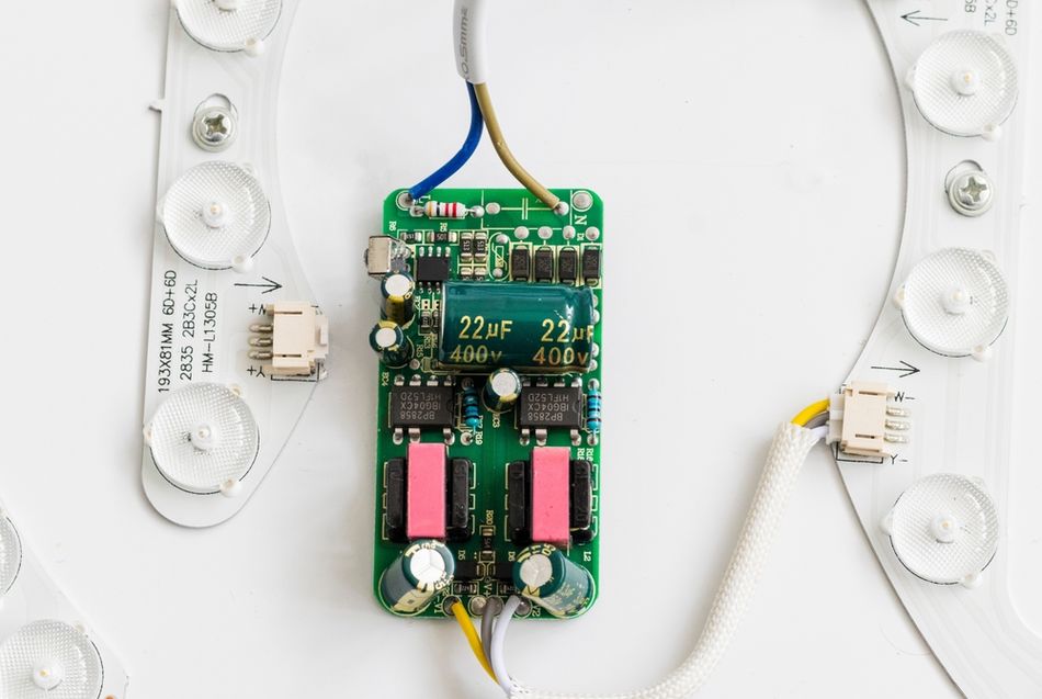
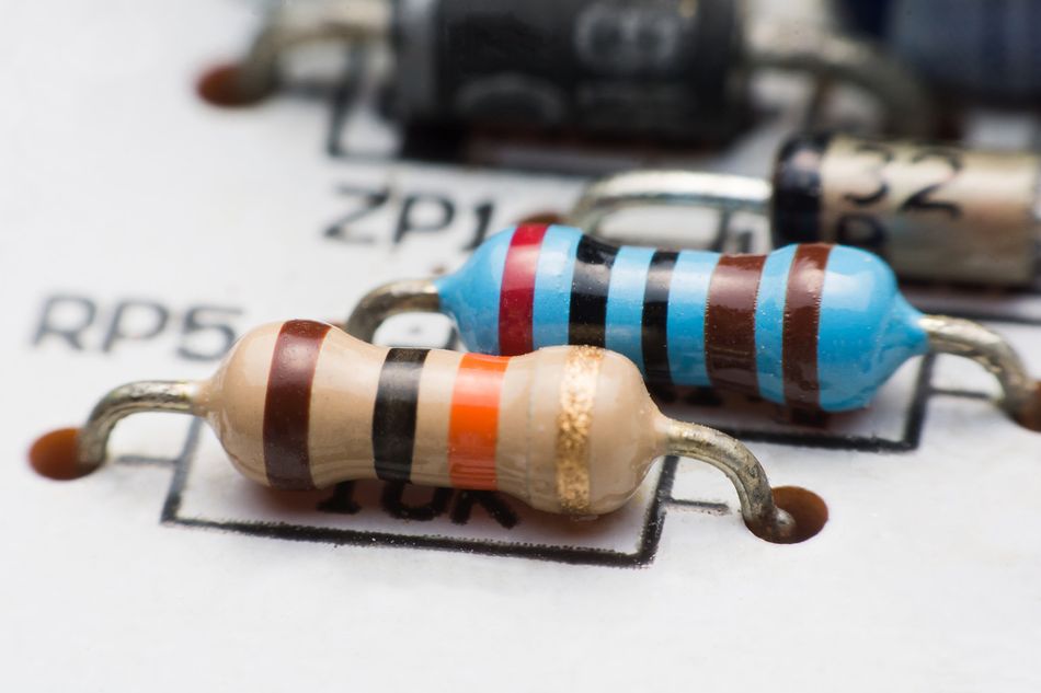
Striped White Resistor to Inhibit or Limit the Flow of Electric Current
Key Takeaways
Definition and Purpose: A current‑limiting resistor is placed in series with a circuit or device to restrict the current to a safe value. It protects components such as LEDs, transistor bases and microcontroller inputs from overcurrent.
Proper Sizing: In addition to the resistance value, engineers must select an appropriate power rating and choose a standard E‑series value slightly higher than the calculated value.
Typical Applications: Current‑limiting resistors are essential in LED circuits, transistor biasing, microcontroller input protection, pull‑up/pull‑down networks and sensor interfacing. They also form the foundation of RC filters and voltage dividers.
Alternatives: For high‑power LEDs or precision applications, constant‑current drivers are preferred. Nevertheless, a simple resistor remains a low‑cost, flexible solution for many digital and hardware designs.
Introduction
In every electronic design, there are limits. Components such as LEDs, transistor bases and microcontroller inputs can handle only a certain amount of current before they fail. Exceeding those limits may lead to damaged devices, intermittent operation or even catastrophic circuit failure. Engineers rely on a current-limiting resistor to protect devices from excessive current, stabilize operating conditions, and ensure predictable circuit behavior under varying loads. Once safeguarding LEDs, controlling inrush current, or managing transient events, a current-limiting resistor provides a reliable, passive method for regulating current flow. Its importance grows as circuits become faster, denser, and more sensitive to electrical stress.
Selecting the correct current-limiting resistor requires understanding resistance values, power dissipation, tolerances, and thermal characteristics. This article explores the underlying theory, essential design considerations, and diverse applications that help engineers make accurate component-level decisions.
Fundamentals of Current‑Limiting Resistors
What is a Current‑Limiting Resistor?
A current‑limiting resistor is any fixed resistor used to restrict current to a safe level. It is a resistor connected in series with the circuit to protect against excessive heating in the appliance. In essence, adding resistance increases the total load resistance, thereby reducing current flow according to Ohm’s law: V = I x R. When used in circuits containing non‑linear devices, such as diodes and LEDs whose voltage–current characteristics are not linear, this series resistor prevents a runaway increase in current.

Most electronic components have maximum current ratings. For example, typical indicator LEDs draw up to 20 mA; microcontroller input pins are often rated for only a few milli amps; and transistor bases can be damaged by excessive base current. Exceeding these limits can cause heating, premature ageing or complete failure. Therefore, designers place a resistor in series with the sensitive device to regulate the current.
Why Diodes Need Current Limiting?
LEDs (light emitting diodes) are semiconductor diodes with nonlinear I–V characteristics. They exhibit a relatively constant forward voltage (around 1.7–3.4 V depending on colour) and then conduct increasingly higher current with only small increases in voltage. A small increase in voltage from 2.7 V to 2.8 V can raise forward current from 20 mA to 50 mA. [1]
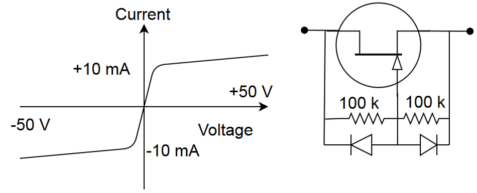
Without a current‑limiting resistor or a dedicated constant‑current driver, this behaviour leads to thermal runaway — an increase in current generates more heat, reducing the forward voltage and causing even more current until the LED burns out. Placing a resistor in series forces the current to vary linearly with voltage according to Ohm’s law, providing a simple and inexpensive method for current control.
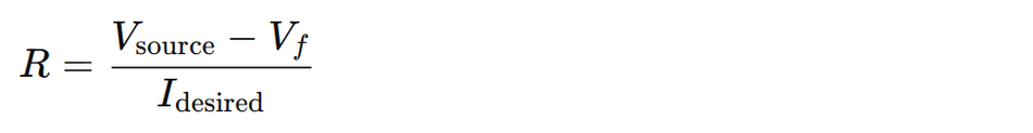
Ohm’s Law and Current Limiting
Selecting a current-limiting resistor begins with Ohm’s law. The required resistor must drop the excess voltage between the source and the device’s forward voltage. The resistor value is calculated as:
where:
V (source) is the supply voltage
V (forward) is the LED’s forward voltage drop
I (desired) is the desired current through the LED
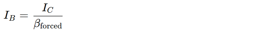
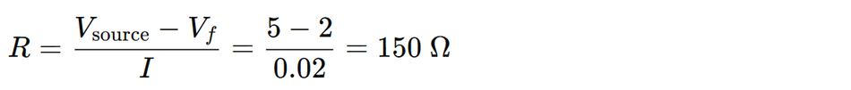
For a 9 V supply and a red LED with Vf = 1.8 V, at 10 mA,
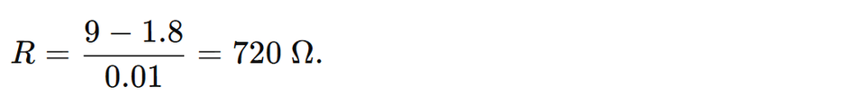
Engineers typically choose the next higher standard value (e.g., 820 Ω) to keep current slightly below the maximum rating and add design safety margin.
Important: Power dissipation must also be checked:

Here, the resistor must be rated above this value!
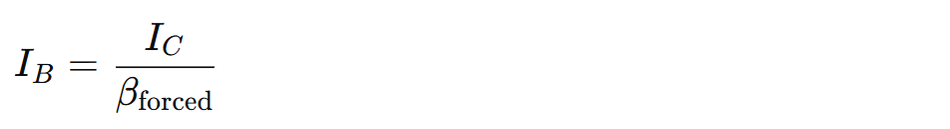
Current Gain and Resistors in Transistor Circuits
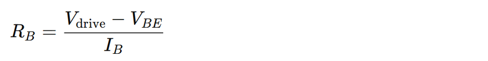
Bipolar Junction Transistors (BJTs) base–emitter junction behaves like a diode (~0.7 V for silicon). Without a base resistor, this junction draws uncontrolled current, stressing the driving device. The required base resistor is:

Since:
The combined design formula becomes:
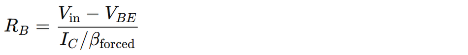
Designers often use a forced beta (50–60% of nominal) to guarantee saturation.
In MOSFET circuits, the gate does not conduct DC current, but gate resistors still play a role. The gate resistors limit inrush current and damp oscillations, and larger values slow transitions, trading electromagnetic interference (EMI) for switching speed. [2] While not strictly current‑limiting in the sense of series current, gate resistors limit the instantaneous charging current into the capacitive gate and hence protect the driver.
Input Protection for Microcontrollers
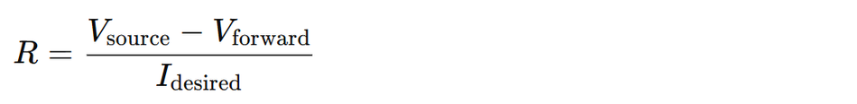
Microcontroller GPIO pins are susceptible to overcurrent and voltage spikes. A small series resistor is typically placed between the external signal and the input. The recommended values range from 100 Ω to 10 kΩ, with ~1 kΩ suitable for most digital I/O lines. This resistor limits current during ESD events, protects internal clamping diodes, reduces stress from voltage overshoot, and forms an RC filter when paired with a capacitor. For additional robustness, designers sometimes add Schottky diodes or zener clamps. [3]
Important: The resistor must satisfy:
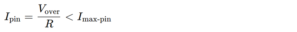
ensuring the absolute maximum ratings of MCUs are never exceeded.
Recommended Reading: Transistor as a Switch: Theory and Practical Implementation for Digital and Hardware Engineers
Designing Current‑Limiting Resistors for LEDs
Gathering Device Parameters
To design an LED current‑limiting resistor, you need:
Supply Voltage – the voltage provided by the power source or microcontroller.
Forward voltage – the voltage drop of the LED at the desired operating current. LED datasheets provide typical values; for common colours they range from 1.7 V to 3.4 V.
Maximum or Desired Forward Current – typical indicator LEDs are rated for 20 mA; high‑efficiency LEDs can be bright at 5–10 mA; microcontroller pins often source only 4–20 mA.
Calculating the Series Resistor
The resistor value follows directly from Ohm’s law:
Selecting a slightly lower current increases LED longevity.
Example: For a 5 V supply and a red LED with Vf = 2 V, at 10 mA,

Because the E12 series does not contain 300 Ω, the next-higher standard value 330 Ω is used, reducing the current to ~9 mA.
For a 3.3 V microcontroller driving a blue LED at 5 mA:

Nearest E12 value: 68 Ω.
Selecting a Standard Value
Resistors are produced in E-series families (E6, E12, E24, E48, E96).
E12 (5%) is the most widely available and usually adequate.
If the calculated value sits between two standard values, choose the next higher value to gently reduce current and extend the LED’s life.
Power Dissipation and Wattage Rating
Every resistor must safely dissipate heat. The power across the resistor is:

For LEDs:

Example: The LED drawing 10 mA through a 330 Ω resistor dropping 3 V:

A ¼-W resistor provides a comfortable safety margin.
Best practice is selecting a resistor rated for at least twice the calculated dissipation.
Colour‑Code Table for Typical LED Resistors
The table below summarizes recommended resistor values for driving single indicator LEDs at roughly 10 mA from common supply voltages. Forward voltage values are typical. Always consult the LED datasheet for precise values.
| LED Color | Vf | 5 V Supply | 3.3 V Supply | Notes |
| Red | ~1.8 V | R = 320 Ω → 330 Ω | R = 150 Ω → 150 Ω | Low forward voltage; small resistor needed |
| Green | ~2.0 V | R = 300 Ω → 330 Ω | R = 130 Ω → 150 Ω | Typical indicator green LEDs |
| Blue | ~3.0 V | R = 200 Ω → 220 Ω | R = 30 Ω → 33 Ω | High-voltage LED |
| White | ~3.2 V | R = 180 Ω → 180 Ω | R = 10 Ω → 10 Ω | Similar to blue; exact Vf values |
Note: For microcontroller pins that source limited current (e.g., 20 mA maximum), choose a higher resistor value (like 330 Ω to 560 Ω) to reduce current to 5–10 mA.
Series and Parallel LED Strings
LEDs in Series
The forward voltages add:
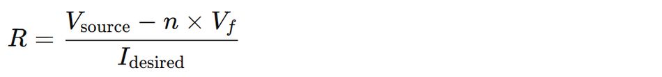
Example: Three red LEDs (1.8 V each) from 12 V at 20 mA:

270 Ω exists in the E12 series.
LEDs in Parallel
Connecting LEDs directly in parallel without individual resistors is generally discouraged because forward-voltage variations can cause current hogging. If you need multiple LEDs in parallel, provide a separate resistor for each branch to equalize current. For example, two green LEDs from a 5 V supply may each use a 330 Ω resistor; tie the LED–resistor series branches in parallel.
Alternative to Resistor: Constant‑Current Drivers
For high‑power LEDs or applications requiring precise brightness, a constant‑current driver is preferable. Constant‑current drivers adjust the output voltage to maintain a fixed current regardless of load changes. The constant current drivers ensure steady current even when resistance changes, while constant voltage drivers supply a fixed voltage and rely on external resistors.
It is recommended to use constant‑current drivers for reliability, but resistors are still needed when using constant‑voltage supplies. The constant‑current drivers reduce variation caused by LED binning, temperature changes, and supply fluctuations.
Recommended Reading: What Is a Resistor in a Circuit? Theory, Types, and Practical Applications
Current‑Limiting Resistors in Transistor Circuits
Base Resistors for BJTs
When using a BJT as a switch, designers supply a base current that is a fraction of the collector current. The base resistor limits the base current, and the transistor saturates when the input signal drives sufficient base current. To guarantee saturation, the required base current is calculated as:
Once I(B) is known, the base resistor is calculated as:
Example: The transistor must sink I(C) = 200 mA to drive a relay.

With a 5 V microcontroller drive signal:
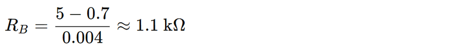
Selecting 1 kΩ provides ~4.3 mA of base current, safely saturating the transistor while staying within the sourcing limits of many MCU pins. Designers must always confirm that the microcontroller can supply the required base current; if not, a MOSFET or a transistor driver stage is recommended.
Gate Resistors for MOSFETs
MOSFET gates do not draw steady current, but they do have capacitance. Driving a MOSFET gate with no resistance can cause high transient currents and ringing. The gate resistor limits inrush current and damps oscillations; larger values slow switching transitions but reduce EMI. Typical gate resistor values range from 10 Ω to several hundred ohms, depending on the gate charge and switching frequency of the MOSFET. In high‑frequency switching regulators, dedicated gate driver ICs deliver amperes of peak current and often use small gate resistors (1–10 Ω) to control edge rates.
Emitter Resistors and Current Sensing
Resistors placed in the emitter of a BJT or the source of a MOSFET provide another method of current limiting and sensing. By measuring the voltage across the resistor, designers can implement feedback to control current. These current‑sense resistors are often low‑resistance (milliohm to ohm range) and high‑precision components used with differential amplifiers to monitor current for power management. Selecting the right value involves balancing measurement resolution and power dissipation; in high‑power designs, sense resistors may dissipate significant heat and require appropriate power ratings.
Protecting Microcontroller Inputs
Series Resistors and RC Filters
Microcontroller digital inputs typically include internal ESD protection diodes connected to ground and the supply rail. Large voltage transients can overstress these diodes, inject noise into the power rail, or corrupt logic levels. The simplest protection method is a series input resistor sized so that its voltage drop does not disturb input thresholds.
Because microcontroller input impedance is extremely high (often greater than 20 MΩ), a series resistor in the hundreds of ohms to tens of kilohms range introduces negligible loading. A commonly used value is 1 kΩ, which effectively limits current during ESD events and protects the clamping diodes.
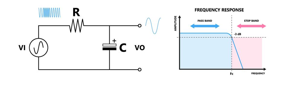
Adding a small capacitor from the input to ground turns the resistor into an RC low‑pass filter. This configuration filters high‑frequency noise and improves EMC performance. Selecting the resistor and capacitor based on the fastest edge of the signal: choose R (often 1 kΩ) and then pick C so the RC time constant is at least one‑tenth of the signal period. For a 1 kHz input, using 1 kΩ and 0.01 µF yields a 10 µs time constant, which filters noise but passes the signal correctly. For slower signals (switches, buttons), larger capacitances can be used.
Clamping with Diodes and Zener Regulators
While series resistors limit current, they do not clip excessive voltages. Adding external Schottky or zener diodes provides voltage clamping. Schottky Diodes clamp both positive and negative transients; the series resistor protects the diodes from overcurrent. For high‑voltage inputs, a zener diode can replace the positive clamp: the resistor must be small enough to provide sufficient current for zener breakdown (approx. 1 mA minimum).
Pull‑Up and Pull‑Down Resistors
Pull‑up resistors tie unused or switchable inputs to a known logic high; pull‑down resistors perform the opposite. The typical pull‑up values range from 4.7 kΩ to 10 kΩ. Smaller resistances (e.g., 1 kΩ) draw more current but provide stronger bias; larger values save power at the expense of noise susceptibility. Most microcontrollers offer internal pull-ups configurable via firmware. External pull-ups are used when connecting mechanical switches, open-collector outputs, or open-drain interfaces such as I²C, which commonly use 2.2 kΩ to 10 kΩ pull-ups depending on bus speed and capacitance.
Recommended Reading: How Does a Zener Diode Work? Theory, Operation & Practical Applications
Practical Implementation Guidelines
Choosing the Right Resistor Type
Resistors come in various technologies: carbon film, metal film, wire‑wound, thick‑film chip resistors and specialized current‑sense resistors. For most low‑power current‑limiting applications (LEDs, transistor bases, microcontroller inputs), metal‑film through‑hole or thick‑film surface‑mount resistors suffice.
When currents exceed 0.25 A or when accurate sensing is required, use power resistors or precision shunt resistors with low tolerance and temperature coefficient. A current‑limiting resistor stabilizes the power supply if it fluctuates, but this requires a resistor that can handle potential surges. [4]
Layout and Placement
Place current‑limiting resistors as close as possible to the device they protect. Keeping traces short minimizes noise pickup and reduces parasitic inductance. For LED arrays, group resistors to simplify routing while ensuring each LED has its own resistor. In microcontroller input protection circuits, place the resistor before any filtering capacitor; this ensures the resistor sees high‑frequency spikes and limits current into the input and diodes.
Temperature and Derating
Resistors change value with temperature. Metal‑film resistors typically have ±100 ppm/°C temperature coefficients, while wire‑wound resistors can be lower. In high‑temperature environments or when precise current is critical, factor in the temperature coefficient in design calculations. Derate the power rating of the resistor according to ambient temperature; many resistor datasheets provide derating curves.
Potentiometers and Variable Brightness
Adjustable current limiting can be achieved by replacing the fixed resistor with a variable resistor (potentiometer). In other words, it is using a variable resistor in series with a fixed current‑limiting resistor to implement dimming. For example, combining a 100 Ω resistor with a 500 Ω potentiometer allows users to adjust LED brightness. When designing such circuits, ensure that the total resistance never goes below the minimum required to protect the LED at the highest supply voltage.
Inrush Current Limiting
In power supply circuits, a surge resistor or thermistor can limit inrush current when switching on capacitive loads. Negative‑temperature‑coefficient (NTC) thermistors have high resistance at low temperatures, limiting initial current; as they heat up, their resistance drops, reducing losses. Positive temperature coefficient (PTC) thermistors operate in the opposite direction and are used in resettable fuses. While these components are beyond simple fixed resistors, they illustrate how resistance is used to protect circuits from sudden current surges.
Recommended Reading: Linear vs Switching Power Supply: Understanding the Differences
Case Studies and Worked Examples
Example 1: LED Indicator Driven by a Microcontroller
Scenario: You want to drive a red LED from an Arduino Uno (5 V logic, maximum current per I/O pin is 20 mA). The forward voltage of the LED is 2.0 V.
1. Compute Resistance:
2. Select Standard Value:
The nearest higher E12 value is 180 Ω. Using 150 Ω draws exactly 20 mA, but 180 Ω reduces the current to ~17 mA, improving safety.
3. Power Dissipation:

A ¼ W resistor provides enough margin.
4. Connection:
Place the resistor in series between the Arduino pin and the LED. This design ensures the LED draws about 17 mA (slightly below 20 mA), producing good brightness while protecting the microcontroller pin and LED.
Example 2: NPN Transistor Driving a Relay
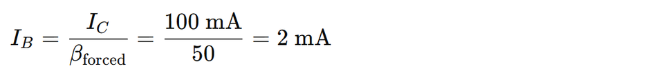
Scenario: A 3.3 V microcontroller controls a 12 V relay that requires 100 mA coil current. The transistor has a typical gain of 100, but you choose a forced gain of 50
1. Base Current Required:
This example uses a design margin of 5 mA, which is also acceptable. Using this,
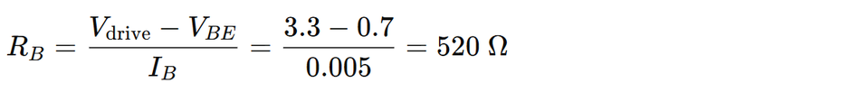
Select 470 Ω, producing ~5.5 mA base current.
2. Check Microcontroller Capability:
5–6 mA is within many MCU pin limits. If not, use a MOSFET or a buffer stage.
3. Flyback Diode:
Place a diode (e.g., 1N4148 or 1N4001) across the relay coil to protect the transistor from inductive kickback.
4. Power Dissipation:
Base resistor power is negligible:

The transistor must be checked for Vce(sat) and thermal dissipation during 100 mA operation.
Example 3: Microcontroller Input Protection with RC Filter
Scenario: The digital input pin is connected to a long cable that may pick up noise. The incoming signal is a 1 kHz square wave.
1. Series Resistor:
It is recommended to use a 1 kΩ resistor. This limits any fault current and forms part of the filter.
2. Select Capacitance:
For a 1 kHz signal, the period is 1 ms. Choose the RC time constant to be at most one‑tenth of this (≈ 100 µs). With R = 1 kΩ,
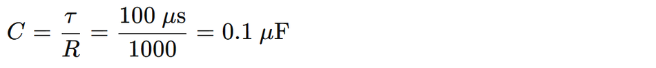
Use a 0.1 µF capacitor to filter high-frequency noise while preserving the 1 kHz signal.
3. Optional Clamping:
Add external Schottky diodes or a zener regulator; if using a zener diode, choose the series resistor small enough (≈ 1 kΩ) to provide the zener’s breakdown current.
Example 4: Power LED Using a Constant‑Current Driver
Scenario: Driving a 3 W white LED (forward voltage ≈ 3.2 V, rated at 700 mA) from a 12 V source.


Using a series resistor would require dropping 8.8 V at 700 mA, resulting in a resistor value of 12.6 Ω and power dissipation of 6.2 W.
Here, a 7 W resistor is bulky, inefficient, and sensitive to supply fluctuations. Instead, use a constant‑current buck driver that adjusts its output voltage to maintain 700 mA. This ensures efficiency and protects the LED from supply variations. You might still include a small series resistor (0.1 Ω) as a current sense element for monitoring.
Challenges, Limitations and Alternatives

Variations in LED Forward Voltage
LED manufacturing tolerances lead to variations in forward voltage. LEDs are binned into voltage categories, and different bins require different resistor values to achieve the same current. Without adjusting the resistor, LEDs from different bins may have varying brightness. For critical applications, measure the actual forward voltage of an LED or use a constant‑current driver.
Thermal Effects and Positive Feedback
Once the LEDs heat up, their forward voltage decreases; at constant voltage, this causes the current to increase. This positive feedback loop can lead to thermal runaway. A current‑limiting resistor helps counteract this because resistors have a positive temperature coefficient (resistance increases with temperature). Nonetheless, in high‑power applications, dedicated drivers with thermal feedback are safer.
Efficiency Considerations
Resistors dissipate power as heat. In low‑power indicator circuits, the losses are negligible, but in larger systems, the wasted power can be significant. Using resistors to drop large voltages (e.g., powering a 2 V LED from a 12 Volts supply) is inefficient and generates heat. If used incorrectly, the design or circuit board can burn out. Designers normally use voltage regulators, constant‑current drivers, inverters or switching converters to improve efficiency.
RC Filters and Signal Integrity
While RC filters reduce noise, they also slow edges. For high‑speed signals, too large a resistor or capacitor can degrade rise times and delay thresholds. Selecting the RC time constant relative to the signal’s period. Simulation can help identify the trade‑off between noise filtering and signal integrity.
Alternatives to Fixed Resistors
In adjustable electronic circuits, potentiometers, digital rheostats, or constant‑current sink ICs provide tunable current limiting. For example, LED dimmers use pulse‑width modulation (PWM) rather than resistors to control brightness. In precision analog circuits, current regulators built from operational amplifiers and sense resistors provide accurate, temperature‑stable current limiting.
Recommended Reading: Low Pass Filter vs High Pass Filter – Theory, Design, and Applications
Conclusion
Current-limiting resistors remain foundational elements in modern electronic design, providing simple and reliable protection for sensitive components. By restricting current, shaping signal behavior, and absorbing excess voltage as heat, they ensure safe operation across microcontrollers, LEDs, transistors, and mixed-signal interfaces. Effective implementation requires a solid understanding of Ohm’s law, device I–V characteristics, resistor tolerances, and power-rating constraints. Engineers must also consider supply variations, component placement, and standard E-series values when selecting parts. While series resistors handle most current-limiting tasks, advanced methods (constant-current drivers, RC filters, clamping diodes, and current-sense networks) offer greater control for demanding applications. Mastering these principles enables the creation of robust, predictable, and efficient electronic systems.
Frequently Asked Questions (FAQs)
1. What is a current‑limiting resistor?
A. The current‑limiting resistor is a fixed resistor placed in series with a device to control the current through that device. It protects components with low current ratings (such as LEDs, transistor bases and microcontroller inputs) from overcurrent by dropping the excess voltage according to Ohm’s law.
2. Why do I need a resistor if I’m using a constant‑voltage LED driver?
A. The constant-voltage drivers do not regulate current, and LEDs draw more current with small voltage changes. A series resistor stabilizes current and prevents thermal runaway when power supply voltage or LED characteristics vary.
3. What is the difference between a base resistor and a pull‑up resistor?
A. A base resistor limits current into the base of a BJT, ensuring the transistor does not draw excessive current and saturates properly. The pull-up resistor biases an input or open-collector output to a defined logic level and typically has a much larger value.
4. Can I drive multiple LEDs with one resistor?
A. Yes, if the LEDs are in series and the supply voltage exceeds their combined forward voltages. Parallel LEDs should not share one resistor; each branch needs its own resistor for equal current distribution.
5. When should I use a constant‑current driver instead of a resistor?
A. Use a constant-current driver for high-power LEDs or when stable brightness and efficiency are critical. Drivers maintain precise current despite variations in voltage, temperature, or LED-to-LED differences. Resistors are acceptable only for low-power indicators.
References
[1] ResearchGate. Basics of Light Emitting diodes, Characterizations and Applications [Cited 2025 December 01] Available at: Link
[2] Toshiba. MOSFET Gate Drive Circuit [Cited 2025 December 01] Available at: Link
[3] ResearchGate. ESD Protection Structure with Reduced Capacitance and Overshoot Voltage for High Speed Interface Applications [Cited 2025 December 01] Available at: Link
[4] Wevolver. What Is a Resistor in a Circuit? Theory, Types, and Practical Applications [Cited 2025 December 01] Available at: Link
in this article
1. Key Takeaways2. Introduction3. Fundamentals of Current‑Limiting Resistors4. Designing Current‑Limiting Resistors for LEDs5. Current‑Limiting Resistors in Transistor Circuits6. Protecting Microcontroller Inputs7. Practical Implementation Guidelines8. Case Studies and Worked Examples9. Challenges, Limitations and Alternatives10. Conclusion11. Frequently Asked Questions (FAQs)12. References