How to Wire a Potentiometer: A Comprehensive Guide for Engineers
Learn how to wire a potentiometer in various configurations (voltage divider, rheostat, sensor) with this in-depth guide. We cover various potentiometer types, provide step-by-step wiring instructions, offer circuit design tips, highlight common mistakes, and include real-world examples.

07 Jul, 2025. 22 minutes read
Key Takeaways
A potentiometer is a 3-terminal variable resistor acting as a voltage divider or a 2-terminal rheostat for precise analog control.
Wire a pot as a voltage divider using all three terminals, or as a rheostat using two, noting that end-terminal orientation flips output behavior.
Various potentiometer types like linear, logarithmic, multi-turn, and digital serve specific applications from general control to audio volume and precise calibration.
Design considerations include selecting appropriate resistance and power ratings, minimizing noise, ensuring tolerance and linearity, and using a 10kΩ pot for microcontroller ADCs.
Avoid wiring errors, exceeding voltage/current limits, and using linear pots for audio volume (instead, use log pots) to prevent erratic behavior or damage.
Introduction
Potentiometers are fundamental components in electronics, acting as adjustable resistors or voltage dividers in countless circuits. Whether you’re designing a volume knob for audio or establishing a sensor interface for a microcontroller, knowing how to wire a potentiometer correctly is crucial. In modern electronics design, potentiometers are ubiquitous, as their global market is projected to reach $3.88 billion by 2029. It reflects their enduring importance in both analog and digital systems.
In this article, we’ll explore what potentiometers are, the different types available, and step-by-step wiring methods for various use-cases (voltage divider, rheostat, sensor). We’ll also discuss circuit design considerations (such as loading effects, power rating, and layout tips), provide real-world application examples (from audio volume controls to sensor reading), and highlight common mistakes to avoid. By the end of this guide, you’ll have a solid understanding of potentiometer wiring and best practices.
What is a Potentiometer?
A potentiometer is a three-terminal resistor with an adjustable middle terminal (the wiper) that “taps” somewhere along a resistive element. By adjusting the wiper’s position, you change the resistance ratio between the wiper and the end terminals, which in turn divides the voltage applied across the end terminals.
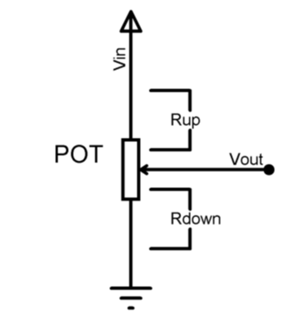
In essence, a potentiometer is a built-in voltage divider that provides a variable output voltage. If you connect a fixed voltage (Vin) across the two end terminals, the voltage at the wiper (Vout) is a fraction of Vin determined by the resistances. This fraction follows the classic formula for a divider:

where Rup is the resistance from the wiper to the Vin side, and Rdown is the resistance from the wiper to the ground side. By moving the wiper, you effectively change Rup and Rdown, thus adjusting Vout continuously from 0 V up to Vin.
Potentiometers are constructed from a variety of composite materials depending on the desired characteristics. These materials usually include:
usually constructed from
Carbon-composition tracks - for general use
Cermet (ceramic/metal mix)
Wirewound resistive elements - for high-power applications
Conductive plastic - for stability
Moreover, they come in rotary form (with a knob) or linear form (slider). Because they are passive devices, they don’t need a power supply to operate – they simply divide whatever voltage is applied.
Potentiometer vs. Rheostat
A rheostat is essentially a potentiometer used with only two terminals (one end and the wiper) to act as a variable resistor controlling current. Since they are often confused, here are some key differentiators to consider:
Feature | Potentiometer | Rheostat |
Terminals | Three | Two (a potentiometer wired in a specific way) |
Primary Use | Voltage division, precise voltage control | Current control, simpler current adjustments |
Typical Apps | Tuning circuits, volume control | Lamp dimmers, motor speed controllers |
Current Handling | Minimal current (feeds high-impedance inputs) | Often higher currents (designed to dissipate heat) |
Physical Characteristics | Generally smcircuit baller | Usually larger or wirewound |
Potentiometers are found in many applications, such as:
Volume controls in audio gear
Position sensors in joysticks and servo mechanisms
Dimmer controls for lighting
Calibration trimmers on circuit boards.
Their versatility and simplicity make them essential components in analog electronics. However, they are generally not used to directly handle large power levels. A potentiometer should typically not be used to drop significant power (more than about a watt) because it would dissipate that energy as heat.
Types of Potentiometers
Potentiometers come in a variety of types and form factors, each suited to different purposes. Understanding the types will help you choose the right pot and wire it correctly for your application. Below are the main categories:
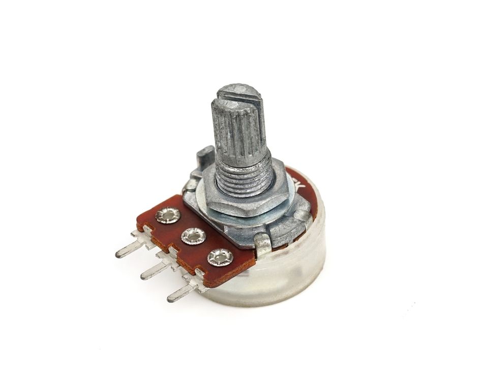
Rotary Potentiometers (Single-Turn)
A rotary potentiometer is the classic round pot controlled by rotating a shaft. The resistive element is arranged in a circular track. A wiper attached to the shaft sweeps along the track as you turn the knob. Standard single-turn pots typically rotate about 270° from end to end. These are widely used for user controls like volume knobs, tone adjustments, etc.
For example, most audio equipment knobs are rotary pots with an audio taper (discussed below) for volume. Rotary pots are easy to adjust and come in various sizes (common resistance values might be 1 kΩ, 10 kΩ, 100 kΩ, etc.).
Logarithmic (Audio Taper) Potentiometers
Not all potentiometers offer a linear change in resistance with shaft position. Logarithmic potentiometers, also known as audio taper pots (often marked "A"), have a non-uniform resistive track. This design causes the output voltage to change logarithmically with knob rotation, mirroring the human ear's logarithmic response to sound.
For instance, an audio taper pot set to its midpoint might output only about 10% of the total voltage, unlike a linear pot, which would output 50%. This characteristic makes audio taper pots ideal for volume and tone controls, ensuring that the "halfway" point on the dial sounds like half volume to our ears.
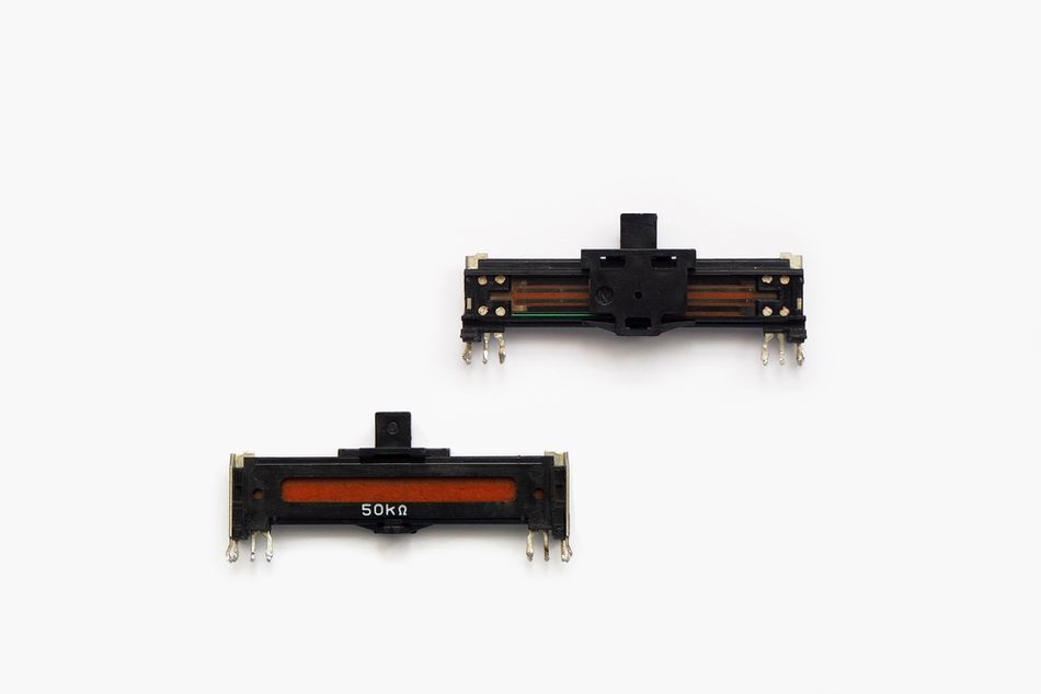
Linear and Slide Potentiometers
A linear potentiometer has the resistive element laid out in a straight line. The wiper moves linearly across this element (often via a slider). Slide potentiometers are simply linear pots with a sliding knob that you push back and forth. They provide the same function as rotary pots, but in a straight-line form factor, which can be more intuitive for certain controls (like a mixing console fader). Linear pots have a direct proportional relationship between knob position and resistance change.
They are common in applications like studio mixing boards (for smooth fader control of audio levels), or as position sensors where a straight motion is being measured (e.g., a sliding rheostat in a mechanical mechanism).
Digital Potentiometers (Electronic Pots)
Digital potentiometers (sometimes called digipots) are integrated circuits that mimic the function of a potentiometer using an array of resistors and electronic switches. Instead of a mechanical wiper, digital pots have addresses or commands that select a tap on a resistor ladder, typically via an I²C or SPI interface. They often provide 32, 64, 128, or 256 discrete steps of resistance.
Digital pots are used when you need remote or programmable control of resistance, such as electronically adjusting a volume or calibration from a microcontroller. They cannot handle high currents or voltages (usually limited to low-voltage analog signals, e.g., 5 V or ±5 V max and a few mA), but they offer advantages like no mechanical wear and the ability to change automatically.
Multi-Turn and Precision Potentiometers
For fine adjustment, multi-turn potentiometers are used. These can be rotary pots with a worm-gear mechanism that takes, say, 10 turns of the knob to go from end to end, or slide pots with a screw slider. Multi-turn pots (often 5-turn, 10-turn, or even 20-turn) allow very precise setting of resistance or voltage. They are typically used in calibration circuits and trimming because you can dial in an exact value gradually. For instance, a 10-turn 100 kΩ potentiometer might let you adjust an output with a resolution of a few ohms per degree of knob turn.
Trimmer potentiometers (trimpots) are small potentiometers (often multi-turn cermet types or single-turn with a small screw) meant to be adjusted infrequently, usually with a screwdriver, for calibrating equipment. They are mounted on PCBs for setting biases, offsets, contrast in LCDs, etc.
Suggested Reading: PCB Components: A Comprehensive Technical Guide to Passive, Active, and Electromechanical Parts
To summarize the common types, the table below compares key features:
Type of Potentiometer | Format & Motion | Typical Uses | Advantages |
Rotary Pot (single-turn) | Knob rotation (≈270°) | Volume, tone, and general analog control | Simple, widely available, tactile feedback for the user |
Linear/Slide Pot | Straight-line slider | Audio mixers, position sensors | Intuitive linear control, good for visual sliders |
Log/Audio Taper Pot | Knob (rotary) with log resistive curve | Audio volume, guitar pots | Matches human hearing, smooth volume perception |
Multi-turn Pot / Trimmer | Screw or knob, 5–20 turns | Calibration, precision adjustment | Fine resolution, stable setting (trimmers) |
Digital Pot (IC) | Electronic (I²C/SPI control) | Remote adjustment, automated calibration | No mechanical wear, programmable, and can be integrated into digital systems |
Recommended Reading: Circuit Symbols: A Comprehensive Guide for Electronics Engineers
How to Wire a Potentiometer
Wiring a potentiometer correctly is essential to get the expected behavior. Fortunately, it’s straightforward once you understand the terminals. A standard 3-terminal potentiometer has:
Terminal 1 – one end of the resistive element;
Terminal 2 – the wiper (middle pin);
Terminal 3 – the other end of the resistive element.
Often, terminals 1 and 3 are the outer legs, and 2 is the center leg on the device. The physical casing sometimes even has numbers or a little diagram on it.
There are two primary ways to wire a pot:
Three-terminal connection (Voltage Divider mode) – all three pins used.
Two-terminal connection (Variable Resistor mode) – only two pins used (wiper + one end).
A special case of the three-terminal connection is when we use the pot as a sensor or input device, feeding the wiper voltage into, say, an analog-to-digital converter. That is essentially the same as the voltage divider configuration, so we will cover it together with practical notes.
Wiring as a Voltage Divider
When using the potentiometer as a voltage divider, you connect all three terminals:
Connect one outer terminal (let’s call it Terminal 1) to the supply voltage (Vin or the signal you want to divide). This could be a fixed DC voltage (5 V, 3.3 V, etc.) or any source voltage you need to scale down.
Connect the other outer terminal (Terminal 3) to ground (0 V reference).
Connect the middle terminal (Terminal 2, the wiper) to your output. This output will be an adjustable voltage between ground and Vin, depending on the wiper position.
The potentiometer now functions as an adjustable voltage divider: at one extreme, the wiper is near the Vin end, so output ~ Vin; at the other extreme, the wiper is near ground, so output ~ 0 V. At halfway, if it’s a linear pot, you get ~50% of Vin (ignoring any load effects).
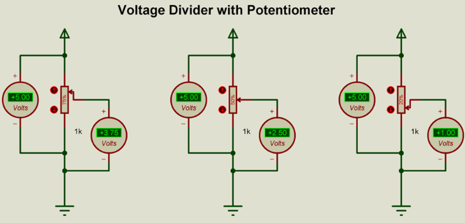
A concrete example: Suppose you have a 1 kΩ potentiometer and connect it between +5 V and ground. The wiper will output anywhere from 0 V up to 5 V. At a given wiper position, say 75% from the ground end, the output will be roughly 3.75V (which is 75% of 5V). Likewise, the voltage varies for different wiper positions as shown in Fig. 4.
Wiring as a Rheostat
To use a potentiometer as a variable resistor (rheostat), you only connect two of the three terminals. The wiper (Terminal 2) must be one of them, and either one of the outer terminals (Terminal 1 or 3) is the other. The unused terminal is left unconnected. Effectively, the pot becomes a single adjustable resistor between the chosen end and the wiper.
Steps for wiring a rheostat:
Connect one outer terminal to one side of your circuit (e.g., to the supply or an input node that will receive current).
Connect the wiper terminal to the other side of the circuit (e.g., to the load or ground, depending on where you need the variable resistance).
Leave the second outer terminal unconnected, or tie it to the wiper as well (this latter trick ensures if the wiper loses contact, the full resistance is still in circuit, rather than an open).
Now the potentiometer will behave like an adjustable resistor whose value goes from near 0 Ω up to the pot’s full resistance. For instance, if you have a 10 kΩ pot wired as a rheostat, at one extreme the wiper is at the end connected, effectively 0 Ω between the two used terminals (actually a few ohms residual); at the other extreme, you get the full 10 kΩ between them; in between, some intermediate resistance. If the pot has a linear taper (often marked “B” on the pot), the resistance is roughly proportional to the wiper position. So halfway gives about 5 kΩ (for a linear 10 kΩ pot).
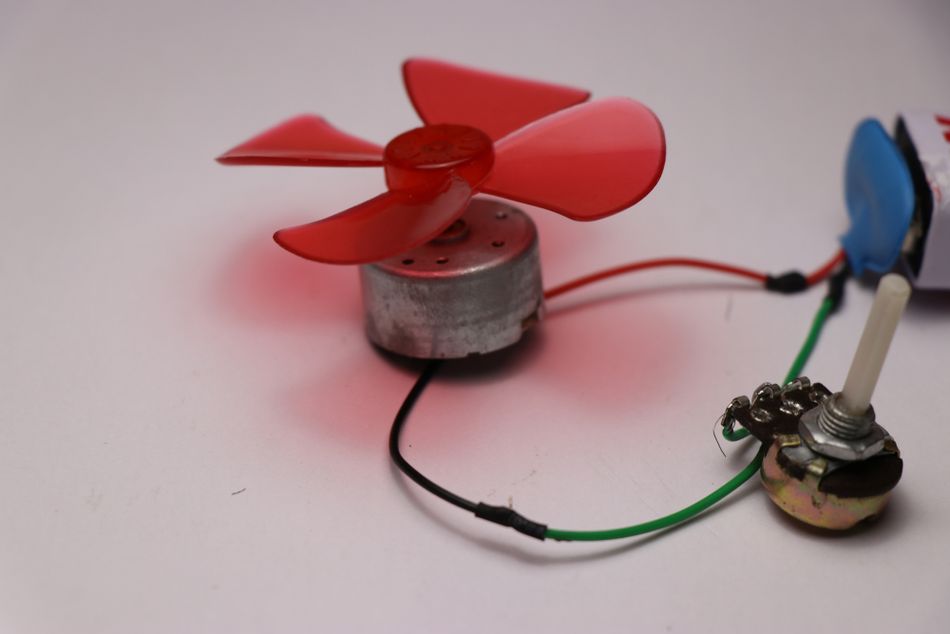
A practical example of rheostat use could be LED brightness or motor speed control. Suppose you want to control the brightness of an LED by placing a variable resistor in series. You could use a small 500 Ω pot as a rheostat in series with the LED and a fixed resistor to vary current. Likewise, you can control the speed of a small DC motor – historically, a power rheostat (low-ohm, high-watt pot) was put in series with the motor to adjust current. Modern designs use PWM or a driver IC, but the rheostat concept is the same.
Suggested Reading: What Causes Voltage Drop?
Wiring a Potentiometer as a Sensor (Voltage Input to ADC)
Using a potentiometer as a position sensor or as a variable input (for example, a knob that feeds into a microcontroller’s analog-to-digital converter) is the same as the voltage divider configuration, with one important addition: the wiper output should typically go into a high-impedance input (like an ADC) or a buffer, to avoid loading the divider.
Connections:
One outer pin to a reference voltage (commonly the microcontroller’s analog reference, e.g. +5 V or +3.3 V).
The other outer pin is connected to ground.
Wiper to the analog input pin of the microcontroller (and also perhaps to a capacitor to ground for noise filtering).
This yields an analog voltage that the MCU can read, corresponding to knob position. For example, an Arduino with a 10-bit ADC will read values 0–1023 as the pot moves from 0 V to Vref (5 V typically). The code to read a potentiometer is straightforward:
const int potPin = A0;
int sensorValue;
void setup() {
  Serial.begin(9600);
}
void loop() {
  sensorValue = analogRead(potPin);
  float voltage = sensorValue * (5.0 / 1023.0);
  Serial.print("ADC = "); Serial.print(sensorValue);
  Serial.print(", Voltage = "); Serial.println(voltage);
  delay(500);
}
In this Arduino C++ snippet, we connect the pot’s wiper to analog pin A0. The code reads the raw ADC value (0–1023) and converts it to a voltage (assuming a 5 V reference). By turning the pot, you’ll see the readings change.
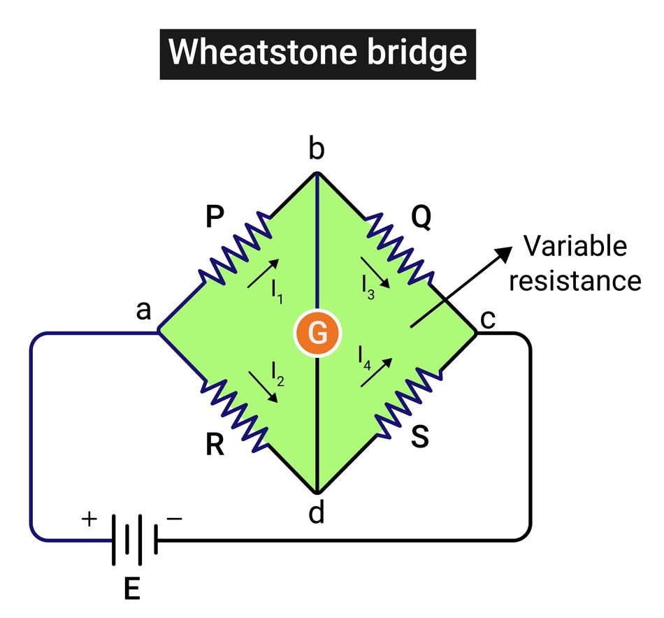
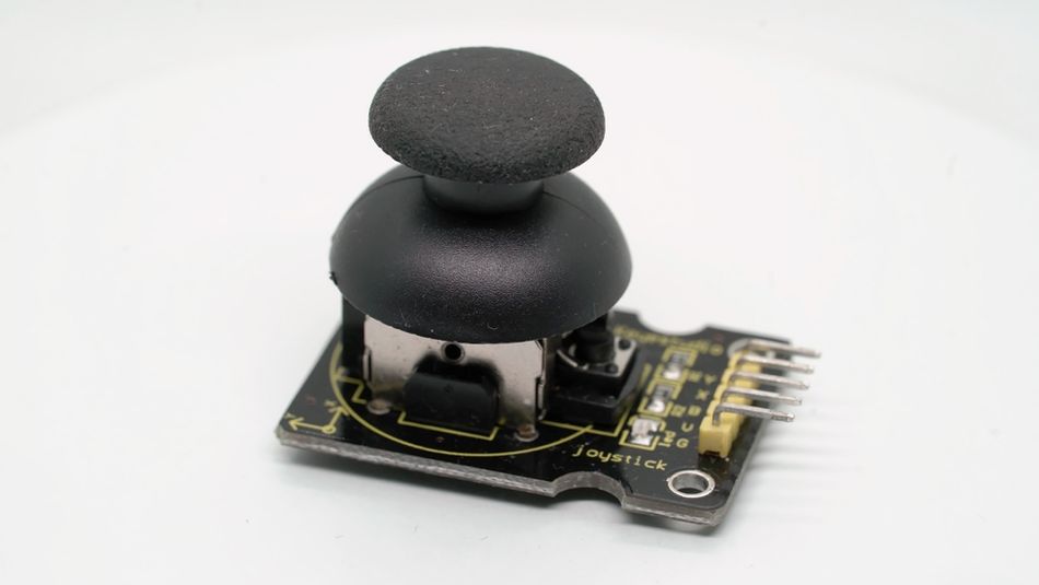
A potentiometer can measure angle or position. Many joysticks, for instance, use two perpendicular slide pots to measure X and Y position. Another sensor example is a Wheatstone bridge, where a pot might serve as one leg to fine-tune balance or as a variable sensor simulator (though in true Wheatstone measurements, dedicated sensors are used; a pot can simulate or adjust them).
To ensure accuracy in sensor applications, consider the temperature coefficient of the pot and mechanical aspects like linearity of the track (some pots are designed as position sensors with better linearity specs).
Circuit Design Considerations for Potentiometer Wiring
Wiring a potentiometer into a circuit demands meticulous attention to several critical design details.
Loading Effects
The impedance of the circuit connected to the potentiometer's wiper (the load) significantly impacts its voltage division ratio. To minimize loading error, the load's input impedance should be at least 10 times, preferably 100 times, greater than the potentiometer's total resistance. For example, a 10 kΩ potentiometer is suitable for an op-amp input (MΩ range) but would halve the voltage range when connected to a 10 kΩ load. In such cases, a buffer amplifier (voltage follower) should be employed to isolate the potentiometer from the load.
Power Rating and Current
Potentiometers are generally low-power components, typically rated from 0.1 W to 0.5 W. This rating applies to the entire resistive element. When used as a voltage divider, the maximum power dissipation (P=V2/Rtotal) occurs around the midpoint. For a rheostat, the maximum continuous current is Imax=√P/R. Exceeding these limits can cause overheating. Always consult datasheets, especially for higher-power or wirewound potentiometers, and design for dissipation well below the rated maximum for reliability.
Tolerance and Accuracy
Potentiometers, particularly carbon types, often have wide resistance tolerances (e.g., ±20%) and non-ideal linearity. For precise applications, these variations can introduce significant error. Multi-turn precision potentiometers offer tighter tolerances (e.g., ±5% or ±1%) and improved linearity. Alternatively, a calibration routine can compensate for the potentiometer's actual value.
Noise and Stability
Sliding contacts can introduce electrical noise. Mitigate this by using high-quality potentiometers, adding a small capacitor (0.01 µF to 0.1 µF) from the wiper to ground for filtering, or employing oversampling/averaging in digital sensor readings. Over time, potentiometers can become "scratchy," requiring contact cleaner or, for critical designs, sealed units or solid-state alternatives like encoders.
Suggested Reading: Absolute Encoder: Precision Positioning in the Digital Age
Temperature Coefficient
The resistance of most potentiometers, especially carbon types, varies with temperature due to a relatively large temperature coefficient. This can cause output drift in precision or timing circuits. For improved stability, consider cermet or wirewound potentiometers, which offer specified temperature coefficients (e.g., ±100 ppm/°C). Avoid excessive self-heating, which can locally alter resistance.
Physical Mounting and Layout
Careful physical planning is essential. Distinguish between PCB-mount, i.e., through-hole or SMT trimmers, and panel-mount potentiometers. For panel-mounted pots connected to a PCB, keep wires short to minimize noise pickup, especially for high-impedance signals on the wiper. Ensure proper PCB footprints and access to adjustment screws. If the potentiometer has a metal body, grounding it can provide noise shielding. Finally, ensure the potentiometer's orientation aligns with the user's expected direction of increase (e.g., clockwise for increasing output).
Suggested Reading: How to Design a PCB Layout: A Comprehensive Guide
End-of-Travel Stop
At the extremes of travel, a potentiometer's wiper effectively connects to an end terminal. In some circuits, it may be necessary to add fixed resistors in series to limit the operational range, for example, to ensure a minimum resistance to prevent a short circuit or to limit the maximum output voltage to a value slightly less than Vin.
Application Examples of Potentiometer Wiring
Potentiometers are used across a wide range of applications. Here we discuss a few common scenarios, and how the wiring and choice of potentiometer type may differ for each:
Audio Volume Control
The potentiometer functions as a voltage divider to attenuate an audio signal, typically found at the output of a preamplifier. A logarithmic taper rotary potentiometer, with values commonly ranging from 10 kΩ to 50 kΩ for line-level signals or 500 kΩ for passive guitar volumes, is employed. One outer terminal connects to the audio signal source, the other to ground, and the wiper delivers the attenuated signal to the amplifier input.

This logarithmic characteristic aligns with human loudness perception, providing a perceptually smooth volume adjustment across the potentiometer's rotation; a linear taper would cause an abrupt volume drop at the lower end.
Sensor Reading and Calibration
Potentiometers are widely used as sensor inputs and for calibration. A common example is a joystick, which often integrates two perpendicular 10 kΩ slide potentiometers acting as voltage dividers between a supply (e.g., 5 V) and ground. The wiper outputs feed analog-to-digital converter (ADC) inputs of a microcontroller, providing X and Y positional data (e.g., 2.5 V representing the center position).
For calibration purposes, a trimmer potentiometer (often multi-turn, e.g., 50 kΩ) is frequently incorporated onto a printed circuit board (PCB). These are used to adjust parameters such as reference voltages or bias currents precisely. For instance, in a temperature sensor bridge, a trimmer can compensate for offsets.
Potentiometers also serve as transducers, converting physical position into an electrical signal, such as a fuel tank's float position sensor. In automotive applications, specialized long-life, wirewound, or conductive plastic potentiometers are often used for robustness and stability.
Examples Summary Table
To recap these examples and show typical wiring choices, below is a table of common applications, recommended potentiometer types, typical resistance values, and notes:
Application | Recommended Pot Type | Typical Value | Notes |
Audio volume control | Logarithmic rotary (dual-gang for stereo) | 10 kΩ (line level) up to 500 kΩ (instrument) | Use audio (log) taper for smooth volume response. Wire as 3-terminal divider; ensure grounding for low noise. |
Audio tone control (Bass/Treble knobs) | Linear or log rotary pots | 10 kΩ – 100 kΩ | Often used in RC filter networks in amplifiers. Wiring may be part of a filter circuit (not just simple divider). |
Sensor position (joystick, pedal) | Linear slide or rotary pot | 5 kΩ – 50 kΩ | Wire as voltage divider between reference and ground, wiper to ADC. Choose mid-value (e.g., 10 kΩ) for low noise and ADC stability. |
Calibration trim (offset, gain adjust) | Multi-turn trimmer (cermet) | 5 kΩ – 100 kΩ | Wire as needed in circuit (often variable part of resistor network). Multi-turn allows fine tuning; mount on PCB. |
LED dimmer (basic DC) | Rotary pot (as rheostat or part of transistor circuit) | 500 Ω – 5 kΩ (depending on LED current and supply) | If directly in series, use low Ω high-watt pot for significant current. Preferably, use pot to drive a transistor for efficient dimming. |
DC Motor speed (basic) | Wirewound rheostat (power pot) | 10 Ω – 100 Ω (high wattage) | In series with motor. Very inefficient at low speed (drops voltage as heat). Modern designs use PWM controllers with a pot controlling them. |
Microcontroller input (knob for menu/setting) | Linear rotary pot | 5 kΩ – 20 kΩ | Wire as voltage divider to analog input. Often 10 kΩ is chosen (as recommended for many ADCs). Possibly add 0.1 µF cap at ADC input for stability. |
Dual control (e.g., balance or cross-fade) | Dual-gang or center-tapped pot | 50 kΩ – 100 kΩ | Special wiring (e.g., one pot controls two opposing signals). Ensure matching taper and tracking between gangs. |
Common Mistakes in Potentiometer Wiring and How to Avoid Them
When working with potentiometers, a few pitfalls frequently occur. Here are some common mistakes engineers and students make, and tips to avoid them:
Incorrect Terminal Wiring: A classic mistake is mixing up the terminals (especially on a PCB-mounted pot where pin 1 vs pin 3 orientation might be flipped). This can result in the control working backwards (increasing when it should decrease) or not working at all if wired incorrectly.
Avoidance: Always identify the wiper (center pin typically) and the end pins. Datasheets or a quick multimeter test (measure resistance while turning) can confirm which pin is which. Wire according to the desired function (remember: for voltage divider, ends to Vin/GND, wiper to output).
Suggested Reading: What Is In-Circuit Testing? An Essential Guide for Engineers
Using the Wrong Taper: Many have accidentally used a linear pot where an audio (log) taper was needed (or vice versa). The result is a control that feels “bunched up” at one end. For instance, a linear pot as a volume control will get loud quickly and have little change in the last half of its rotation.
Avoidance: Choose the correct taper for the application. Most volume controls should be log taper. Many other controls (tone, position, etc.) are fine with linear. Manufacturers label pots with codes (e.g., “A100K” often means audio 100k, “B10K” linear 10k, though note that in some regions A/B labeling can be opposite).
Exceeding Power Ratings: It’s easy to overlook power dissipation in a potentiometer. For example, using a small trim pot to drop voltage in a power circuit can burn it out. Or setting a pot near one end and effectively turning it into a low-value resistor that has to carry current, potentially overheating it.
Avoidance: Calculate the worst-case power in the pot. If used as a rheostat at the midpoint, that’s the max dissipation scenario for a given voltage across it. Use a pot with sufficient wattage or redesign to limit current (for instance, put a fixed resistor in series to take some of the load, so the pot only adjusts a portion).
Floating or No Reference: If you only use the wiper and one end and leave the other end completely disconnected in a divider application, you might inadvertently create a situation where, if the wiper loses contact, the node is floating (undefined voltage).
Avoidance: Always ground the low end (or tie it to a reference) in a divider, and use the full three connections unless there’s a deliberate reason not to. If using as a rheostat (two terminals), consider connecting the unused third terminal to the wiper to guard against an open circuit.
Poor Grounding Causing Hum/Noise: In audio circuits, especially, if the ground connection of the potentiometer is not solid (e.g., a loose jack or a long daisy-chained ground), you can get hum or buzz. A volume pot that isn’t properly grounded on one end will act like an antenna picking up interference.
Avoidance: Use star grounding or a proper ground plane. Ensure the pot’s ground pin goes to the circuit ground with a short path. Shield the wiring if needed.
Recommended Reading: EMI Shielding: Protecting Electronic Devices in a Noisy World
Mechanical Issues: Pots can fail or behave erratically if they are damaged or dirty. Symptoms include scratchy outputs or sudden jumps. A common mistake is ignoring the need for a proper knob or mechanical coupling – twisting a tiny trim pot with fingers repeatedly can break it, or using a pot as a structural support can break its leads.
Avoidance: Use knobs for user-facing pots (reduces stress on the shaft). Mount the pot securely; if it’s a PCB mount, ensure it’s soldered well. If it’s a panel mount with wires, consider a strain relief for the wires.
Potentiometer in Unusual Configurations
Beyond the standard uses, sometimes potentiometers get used in creative ways:
Variable splitter or dual output control: For example, using one pot to control two different parameters inversely (like a cross-fader that fades one channel in while fading another out). This can be done by using the wiper as output to one circuit and maybe the inverted position (voltage from wiper to the other end) to another. Some special pots even have center taps or dual tracks to facilitate this.
Ganged potentiometers with different values/tapers: In some tone control circuits (like guitar tone knobs), a dual-gang pot might have one gang linear, one gang reverse log, etc., to achieve a specific EQ curve. Wiring those can be tricky and very specific to the circuit design.
Pseudo-log using linear pot and resistor: If you only have a linear pot but need an audio-like taper, one trick is to place a fixed resistor across part of the pot (from wiper to one end) to approximate a log curve. This changes the effective taper by loading it. It’s a bit beyond this scope, but keep in mind that the behavior of a pot can be modified by external resistors in the network.
Conclusion
Potentiometers are crucial electronic components for adjusting voltage and resistance. They offer versatile control, from basic voltage division to intricate sensor input. Understanding their three-terminal wiring for voltage dividers, or two-terminal for variable resistors (rheostats), is fundamental. Careful consideration of orientation, taper (linear vs. logarithmic for audio), and electrical limits prevents common pitfalls like wiring mistakes or component damage.
While digital potentiometers offer software control, analog pots provide tactile, immediate adjustment, remaining prevalent in diverse applications from DIY electronics to professional lab equipment. Both analog and digital solutions have their place, and mastering their principles opens up more design possibilities for engineers and students alike, allowing for hybrid systems or future solid-state advancements.
FAQ
How do I wire a 3-pin potentiometer correctly?
Connect one of the outer pins to your voltage source (e.g., +5 V) and the other outer pin to ground (0 V). Then connect the middle pin (wiper) to the point in your circuit where you want the adjustable voltage. This way, the wiper provides a voltage between 0 V and +5 V as you turn the knob. If you get it backwards (increases when you expect a decrease), simply swap the outer pins.
2. Can I use a potentiometer as a variable resistor (two terminals)?
Yes. To use a pot as a variable resistor (rheostat), connect the wiper and one of the outer terminals into the circuit and leave the other outer terminal unconnected. The pot will then behave like an adjustable resistor between those two terminals. Many people tie the unused terminal to the wiper (effectively shorting them) as a safeguard against the wiper losing contact. Remember, in this 2-terminal mode the total resistance seen is the portion of the track between the wiper and the connected end, which varies with knob position.
3. Does it matter which side (which outer pin) of the potentiometer is connected to ground or Vcc?
Electrically, the pot will function either way as a divider, but it will affect the direction of operation. Conventionally, you wire it so that clockwise rotation increases the output voltage (wiper moves toward Vin). That means connect the clockwise end to Vin and the counterclockwise end to ground. If you reverse them, clockwise will decrease the output. It’s not harmful, but for user-friendliness, you usually want a consistent direction.
4. How do I connect a potentiometer to an Arduino (or any microcontroller)?
Wire the potentiometer as a voltage divider: one outer leg to the Arduino’s 5 V (or 3.3 V if that’s your MCU’s reference), the other outer leg to Arduino GND, and the middle wiper leg to one of the analog input pins (e.g., A0). In code, use analogRead() on that analog pin to get a value proportional to the knob position (0–1023 for a 10-bit ADC). Make sure the pot’s value isn’t too high; around 10 kΩ is ideal for Arduino analog inputs. If you use a much higher value (like 1 MΩ), the analog reading might be noisy or slow to respond due to input impedance issues.
5. What value potentiometer should I choose for my project?
It depends on the application:
For microcontroller analog inputs, 1 kΩ to 50 kΩ will work; 10 kΩ is a common choice (balances current draw and noise).
For audio line-level (volume knobs), 10 kΩ to 100 kΩ is typical. Higher values load the source less, but too high can introduce noise/hiss. 10 k–50 k is a good range for most modern low-impedance sources.
For a bias/gain adjust in a circuit, consider the input impedance of that node. If it’s high, you can use a higher value pot. If it’s low, use a lower value or redesign to use a higher impedance input (perhaps via an op-amp).
For power applications (as a rheostat), use the lowest value that gives you the range you need, and ensure it’s power-rated for the worst case. For example, a 5 Ω or 10 Ω pot for a 12 V/2 A heater control (but that pot would need to handle >24 W, which is impractically high; a better solution is to use the pot to drive a transistor or PWM).
6. What is the difference between a logarithmic (audio taper) and a linear potentiometer?
A linear potentiometer changes the output proportionally to the angle/position – e.g., 50% rotation gives ~50% of voltage. A logarithmic potentiometer has a resistive track shaped so that the output vs. rotation is logarithmic (or sometimes an approximation in multiple segments). This is used because our ears perceive loudness logarithmically; an audio taper pot gives a more uniform perceived change in volume. In practical terms, if you measure resistance from wiper to one end at the midpoint, a 10 kΩ linear pot will read ~5 kΩ at halfway, whereas a log pot might read ~1 kΩ or ~2 kΩ at halfway (10 kΩ total) because it’s giving you less volume (voltage) at the midpoint to account for human hearing response.
7. My potentiometer is very sensitive – most of the change happens in a small part of the turn. Why?
This could be due to using a linear pot in a logarithmic context (like volume), making it seem to all change at one end. Or it could be that the pot’s value is too high relative to the input impedance of the next stage, causing a nonlinear loading effect. If it’s an audio volume issue, switch to an audio taper pot. If it’s a loading issue, ensure the wiper is feeding a high impedance or use a buffer. Another possibility: the pot might be wired as a rheostat in a non-linear circuit (for instance, controlling base current of a transistor, which can be exponential). In such cases, the circuit, not the pot, is causing the sensitivity. The solution there is to redesign the circuit (perhaps use the pot as a divider to drive something in a linear region, or use a different topology).
References
Phidgets Inc., “Potentiometer Guide,” Phidgets Support Wiki, Jul. 11, 2023. [Online]. Available: https://www.phidgets.com/docs/Potentiometer_Guide.
Keysight Technologies, “The Complete Engineer’s Guide to Potentiometers and How to Wire Them,” Keysight Blog, 2023.
J. Smoot, “The Complete Guide to Potentiometers,” Digi-Key Electronics, May 31, 2023. [Online]. Available: https://www.digikey.com/en/articles/the-complete-guide-to-potentiometers.
NextPCB, “Potentiometer Wiring: A Comprehensive Guide,” NextPCB Blog, Apr. 7, 2023. [Online]. Available: https://www.nextpcb.com/blog/potentiometer-wiring.
M. Parkar, “Potentiometer Market: Global Industry Analysis and Forecast (2023–2029),” Maximize Market Research, 2023. [Online]. Available: https://www.maximizemarketresearch.com/market-report/potentiometer-market/148408/.
A. Ghassaei, “Wire a Potentiometer as a Variable Resistor,” Instructables (Autodesk), accessed Nov. 2025. [Online]. Available: https://www.instructables.com/Wire-a-Potentiometer-as-a-Variable-Resistor/.
in this article
1. Key Takeaways2. Introduction3. What is a Potentiometer?4. Types of Potentiometers5. How to Wire a Potentiometer6. Circuit Design Considerations for Potentiometer Wiring7. Application Examples of Potentiometer Wiring8. Common Mistakes in Potentiometer Wiring and How to Avoid Them9. Conclusion10. FAQ11. References