Understanding Potentiometer Pins: Technical Guide for Engineers
This guide explains how potentiometer pins interact with mechanical rotation, resistive tracks, and load conditions across various circuit configurations. It provides clarity for both low-power electronic designs and high-precision embedded systems.

24 Nov, 2025. 14 minutes read
Key Takeaways
Three‑Pin Structure: Every potentiometer has two fixed end pins and a middle wiper pin; understanding their roles is essential for correct wiring and circuit design.
Voltage Divider Operation: Once all three pins are used, the potentiometer divides the input voltage into a variable output proportional to the wiper position.
Variable Resistor Configuration: By shorting one end pin to the wiper and using two terminals, the potentiometer behaves as a two‑terminal variable resistor (rheostat). This configuration is common but has different electrical properties and power ratings.
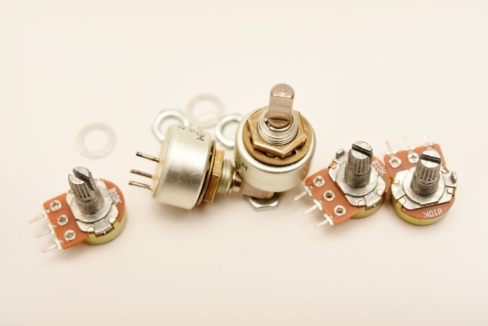
Types and Tapers: Potentiometers are available in rotary, slide, linear, trimmer and digital forms. They can have linear or logarithmic (audio) taper characteristics, which determine how resistance changes with knob position.
Design Considerations: The wiper adds series resistance (up to one‑quarter of the total value at mid‑position) and output impedance; careful selection, buffering and layout prevent measurement errors, noise and excessive power dissipation.
Introduction
Potentiometers have been fundamental to electronic design since the early days of radio, yet they remain vitally important in modern embedded systems. They appear simple, a knob and three pins, but those pins hide a complex interplay of resistive materials, mechanical wear and electrical design considerations. The arrangement of potentiometer pins determines how the component behaves as a voltage divider, signal attenuator, or adjustable resistor. If you are designing a microcontroller‑based sensor interface, building a guitar pedal or calibrating industrial instrumentation, understanding how potentiometer pins function will save troubleshooting time and improve product reliability.
Misinterpreting potentiometer pins often leads to incorrect wiring, signal distortion, or unexpected non-linear responses in sensitive applications. This guide explains how potentiometer pins interact with mechanical rotation, resistive tracks, and load conditions across various circuit configurations. It provides clarity for both low-power electronic designs and high-precision embedded systems.
Theoretical Concepts
Potentiometer Basics
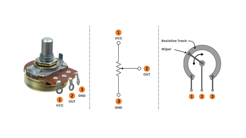
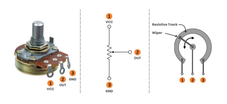
Potentiometer is a three‑terminal adjustable resistor. Internally, a strip of resistive material is formed into an arc or a straight line; two end terminals connect to the ends of this resistive element and the third terminal is a movable wiper that makes sliding contact along the element. The figure below illustrates a rotary potentiometer with the pins labelled. [1] Once the knob is rotated or the slider is moved, the wiper divides the resistive element into two resistances, R1 and R2, whose sum equals the rated resistance of the potentiometer.

This fundamental structure serves as the basis for two primary applications: voltage division and variable resistance.
1. Voltage Divider Principle
Once a voltage (Vin) is applied across the two fixed terminals and the output is taken from the wiper, the potentiometer functions as a variable voltage divider. The output voltage (Vout) is:

Here, R1 is the resistance between the wiper and one end, and R2 is the resistance between the wiper and the other end.
Once the wiper moves along the resistive element, R1 and R2 change while their sum remains constant. The output voltage therefore varies linearly (or logarithmically depending on taper) with the wiper position. This property makes potentiometers ideal for analog user interfaces such as volume knobs, brightness controls and sensor calibration circuits.
2. Variable Resistor Operation
By using only two pins—the wiper and one end—one can configure a potentiometer as a variable resistor.

This configuration, sometimes called a rheostat, allows the potentiometer to control current by altering its effective resistance. However, the design must account for differences between potentiometers and dedicated rheostats. Potentiometers generally handle lower power and current; using them as rheostats for high loads may cause overheating or mechanical failure. Nevertheless, the two‑pin configuration is useful for adjusting bias currents, setting reference thresholds and tuning feedback networks.
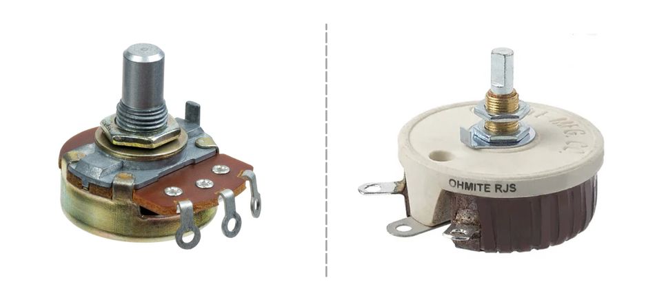
Types of Potentiometers
Potentiometers come in various mechanical forms tailored to different applications. The table below summarises common types and their typical uses:
| Type | Description | Typical Applications |
| Rotary | Circular resistive track with rotating shaft | Audio volume control, tuning circuits, instrumentation |
| Linear/Slide | Straight resistive track with sliding wiper | Mixer faders, lighting dimmers, joystick controls |
| Trimmer | Compact, screwdriver-adjustable component | PCB calibration, sensor bridge balancing, oscillator tuning |
| Dual | Two synchronized potentiometers on one shaft | Stereo audio, differential sensing |
| Digital | Semiconductor-based, controlled by SPI/I²C | Microcontrollers, PGAs, programmable calibration |
Besides mechanical style, potentiometers differ in taper. The linear taper means resistance changes proportionally to knob position: halfway corresponds to half the total resistance. In contrast, an audio or logarithmic taper changes resistance exponentially, matching the logarithmic perception of human hearing; these pots are commonly used for volume control.
Rheostat versus Potentiometer
Understanding the difference between a potentiometer and a rheostat is crucial when selecting among these electronic components.
Both devices are variable resistors, but their typical usage differs.
Potentiometers: Three-terminal devices primarily used as voltage dividers, rated for lower power.
Rheostats: Two-terminal devices designed to control current, typically with higher power ratings.
Designers sometimes repurpose a potentiometer as a rheostat by using only the wiper and one end, but high currents may overheat the resistive element.
Linear and Audio Taper Characteristics
The taper of a potentiometer influences how its output changes with rotation or sliding.
Linear Taper devices have a constant gradient: the resistance between the wiper and a given end changes linearly with position. [2]

Audio (Logarithmic) Taper devices approximate a logarithmic curve, so the majority of the resistance change happens near one end.

This matches the logarithmic perception of loudness and allows smoother control near low volumes. For digital design, linear potentiometers are often preferable when an ADC expects uniform scaling, while audio taper is reserved for human‑perceived controls.
Anatomy of Potentiometer Pins
Identifying the Pins
The typical through‑hole or panel‑mount potentiometer has three terminals arranged in a row. The common pinout conventions state that, Pin 1 and Pin 3 connect to the ends of the resistive track, while Pin 2 is the wiper. In most rotary potentiometer designs, the middle pin serves as the wiper. In a slide potentiometer, it is typically the center tab among the three metal sliders. As the knob rotates or the slider moves, the wiper physically travels along the resistive element, altering the contact point and adjusting the division ratio in a voltage divider or variable resistor configuration.
Once the orientation of a potentiometer is unknown, you can identify the wiper by measuring resistance with a multimeter. Measuring between the middle pin and either outer pin will show a variable resistance as the shaft or slider is moved. If you connect the meter across the two outer pins, the resistance remains constant and equal to the nominal value (e.g., 10 kΩ) of the potentiometer. This simple test helps confirm the pinout on unlabelled or unconventional devices.
The table below summarises the electrical functions of each pin:
| Pin | Description | Typical Connection |
| 1 | One end of the resistive element; defines the starting point of the voltage drop. | Connected to VCC or GND in a voltage divider; to one side of a load in rheostat mode. |
| 2 | Movable contact that divides the resistance; provides output voltage or variable resistance. | Connected to ADC input of a microcontroller, to an amplifier, or to a load in variable resistor mode. |
| 3 | The other end of the resistive element; defines the end point of the voltage drop. | Connected to GND or the supply rail, depending on desired adjustment direction. |
Electrical Behaviour Between Pins
The total resistance between Pins 1 and Pin 3 is fixed and equal to the rated value of potentiometer.

The resistance between the wiper (Pin 2) and each end (Pins 1 and 3) varies as the wiper moves. Ideally,

In practice, wiper contact resistance adds a small series resistance; near the midpoint this wiper resistance can cause the output impedance to be as high as one‑quarter of the total resistance. For example, a 10 kΩ linear potentiometer might have roughly 2.5 kΩ output impedance at mid‑rotation. This finite output impedance interacts with the input impedance of any circuit connected to the wiper, potentially causing measurement errors. To mitigate this, designers often buffer the wiper voltage using an operational amplifier configured as a voltage follower.
Another real‑world phenomenon is tolerance and linearity. Potentiometers have manufacturing tolerances; a 10 kΩ pot may measure anywhere between 8 kΩ and 12 kΩ. Linearity describes how closely the resistance ratio follows the ideal taper. High‑precision or conductive plastic potentiometers offer better linearity than cheaper carbon track pots. Temperature coefficients and mechanical wear also alter performance over time.
Environmental and Mechanical Considerations
The longevity of a potentiometer depends on factors such as mechanical wear, wiper cleanliness, and environmental contamination. Dust, oxidation, or humidity buildup on the wiper can produce crackling or intermittent behaviour in volume control, dimmer, or fader applications. The audio-grade faders and sliders often require periodic cleaning, while sealed trimmer or trimpot types are preferred for harsh environments.
In industrial equipment, selecting a potentiometer with the correct sealing, temperature rating, and mounting style ensures stable operation over the lifetime of the system. Good soldering practice and proper potentiometer wiring in the wiring diagram also help ensure consistent performance in sensitive analog circuits.
Recommended Reading: Understanding Multimeter Symbols: A Comprehensive Guide for Engineers
Practical Implementations
Wiring a Potentiometer as a Voltage Divider
The most common way to use a potentiometer is to create a variable fraction of an input voltage. To implement this:
Disconnect power before wiring to avoid accidental short circuits.
Connect Pin 1 to the positive supply voltage (e.g., 5 V).
Connect Pin 3 to ground (0 V). Some designs reverse these connections to invert the direction of rotation.
Connect Pin 2 (the wiper) to the input of the circuit that reads the output voltage. This may be an ADC input on an Arduino or other microcontroller, the non-inverting input of an amplifier, or another analog input stage.
Optionally place a small resistor (~100 Ω) between Pin 1 and Pin 3 to limit the current if the wiper goes fully to one end and inadvertently shorts the supply.
This connection yields an output voltage proportional to the wiper position. The wiper output follows the classic divider equation:

The output impedance of the divider is:

At the midpoint of a linear potentiometer:

If the load connected to the wiper has low impedance, it can load the divider and skew the output, so a buffer is often recommended.
Example: Biasing an Op‑Amp
Suppose you need to generate a variable reference voltage between 0V and 2.5V for an op‑amp comparator in a 5V system. The 10 kΩ rotary potentiometer wired as a voltage divider provides a continuously adjustable reference at the wiper. Since comparators typically have high-impedance inputs, the approximate 2.5 kΩ output impedance at mid-rotation is acceptable. However, adding a 0.1 µF capacitor from the wiper to ground filters noise and ensures stability.
Wiring a Potentiometer as a Variable Resistor
The potentiometer can also operate as a variable resistor, commonly called a rheostat, using only two pins. To configure it:
Identify the wiper (Pin 2) and choose either Pin 1 or Pin 3 depending on the desired direction of adjustment.
Short the unused outer pin to the wiper by soldering a jumper or tying them together. This ensures that if the wiper loses contact, the circuit still sees maximum resistance rather than an open circuit.
Connect the combined wiper and selected end pin in series with the load you wish to control.
Keep the power rating of the potentiometer in mind; do not exceed its dissipation by passing too much current through the track.
Example: LED Brightness Control
In a simple LED brightness dimming circuit, a 1 kΩ potentiometer can be used as a rheostat in series with the LED and a current-limiting resistor. Rotating the knob changes the total resistance and modifies LED current. Because the potentiometer must carry the LED current, confirm that its dissipation stays within its rating (normally a few hundred milliwatts). For high-power LEDs, a true rheostat or PWM control is safer.
Mechanical Mounting and Soldering
Once mounting a potentiometer on a printed circuit board (PCB) or panel:
Use the correct footprint to ensure alignment; many pots have locating tabs to prevent rotation.
Apply heat quickly during soldering, as prolonged heating can damage the resistive element.
Trimmer potentiometers, especially multi-turn types, often have delicate plastic enclosures that soften under excessive heat.
For frequently adjusted controls, select a component rated for a high mechanical lifespan, conductive-plastic or wire-wound types outperform basic carbon versions.
For slide potentiometer assemblies, ensure the slider mechanism is protected from dust; some models include dust shields or require external sealing.
Interfacing with Microcontrollers
Modern embedded systems often need to convert analog knob positions to digital values. The simplest approach uses the potentiometer as a voltage divider feeding an ADC. Many microcontrollers include 10‑or 12‑bit ADCs with input impedance of several megaohms, so direct connection is acceptable. However, consider these issues:
Source Impedance and ADC Sampling: Some ADCs sample by charging a sample‑and‑hold capacitor. If the output impedance of the potentiometer is high, the sampling capacitor may not fully charge, causing conversion errors. Buffering the wiper signal with an op‑amp or using a lower resistance pot (e.g., 10 kΩ) alleviates this.
Power Consumption: Lower resistance pots draw more quiescent current because the end pins are connected across the supply. For battery‑powered devices, a 100 kΩ pot reduces current draw but increases source impedance; balance these factors in design.
Noise and Filtering: Mechanical wiper noise can be filtered by adding a small capacitor between the wiper and ground. Debouncing may be necessary if the position is read digitally at high speed.
Digital Potentiometers: When physical knobs are undesirable or remote control is required, digital potentiometers controlled via I²C or SPI are a flexible alternative. For example, TPL0102 by Texas Instruments contains 2 independent 256 step potentiometers with non‑volatile memory; it can act as either a three terminal potentiometer or a two‑terminal rheostat and operates from 2.7 V to 5.5 V. [4] Digital pots eliminate mechanical wear and allow calibration in software but have limitations such as finite resolution and low maximum voltage (typically less than 5 V).
Calibration and Trimming Applications
Potentiometers are often used to fine‑tune circuit parameters. For example:
Sensor Bridge Balancing: Wheatstone bridge circuits frequently include a trimmer potentiometer to null out offset voltages. By adjusting the wiper, the bridge can be perfectly balanced for accurate differential measurements.
Frequency Tuning: RC oscillators and filters use potentiometers to adjust frequency or time constants. A small change in the resistance changes the RC constant, enabling calibration of oscillators, phase‑locked loops, or filters.
Bias Adjustment: Amplifier bias currents or transistor base voltages are often set by small trimmer pots in feedback or voltage divider networks. Adjusting the pot tunes the operating point.
Recommended Reading: How to Wire a Potentiometer: A Comprehensive Guide for Engineers
Design Considerations and Best Practices
Selecting Resistance Value
Potentiometers are available in standard values from a few ohms to several megaohms. Selecting the correct value ensures predictable operation in voltage divider circuits, variable resistor configurations, and microcontroller interfaces.
The key factors include:
Load Impedance: Ensure that the output impedance of potentiometer is small relative to the input impedance of the load to prevent loading errors. As a rule of thumb, the load impedance should be at least 10 times larger than the potentiometer value.
Power Consumption: Lower resistance values draw more current when used as voltage dividers. For portable devices, values between 10 kΩ and 100 kΩ strike a good balance.
Noise Sensitivity: High-value potentiometers suffer more from leakage currents, EMI pickup, and resistance changes due to contamination. In precision analog circuits, use lower values and buffer the output voltage using an op-amp.
Output Impedance and Buffering
At mid‑rotation the output impedance of a potentiometer is approximately one‑quarter of its total resistance. This output impedance forms a low‑pass filter with any input capacitance of the following stage (e.g., ADC sample capacitance). To minimise errors:
Use a voltage follower (unity-gain op-amp) to isolate the wiper from the load.
Select a lower-value pot if the load is heavy. Example: a 5 kΩ rotary potentiometer gives roughly 1.25 kΩ output impedance at midpoint.
Add a small capacitor (10–100 nF) from the wiper to GND to filter noise without disturbing DC accuracy.
Tolerance, Linearity and Temperature Coefficient
Manufacturers specify potentiometer tolerances, typically ±20% for carbon composition and ±5% or better for cermet or conductive plastic types. If a circuit requires precise scaling, use a high‑precision potentiometer or calibrate the system in software after measuring the actual resistance.
Linearity indicates how closely the output ratio follows the ideal linear (or logarithmic) curve; better linearity is crucial in audio or instrumentation circuits to avoid distortion. The temperature coefficient (often 200 ppm/°C for carbon track pots) denotes how much resistance changes with temperature; in high‑temperature environments choose low‑TC materials or design compensation.
Mechanical Life and Reliability
Mechanical wear is a common failure mode. The carbon composition pots may wear out after 10,000 – 20,000 cycles, whereas conductive plastic or wire‑wound pots can exceed 1 million cycles. For devices subject to frequent adjustment (e.g., mixing desks), invest in high‑quality pots. Dust ingress and oxidation cause scratchy noise; sealed designs or vacuum‑sealed slide pots mitigate this. For mission‑critical or inaccessible systems, digital potentiometers eliminate mechanical wear.
Safety and Power Handling
Potentiometer power ratings typically range from 0.05 W to several watts. Always ensure the power dissipated across the resistive track stays below its rating:

The highest stress occurs when the wiper is at an extreme, forcing the supply voltage across only a portion of the track. To ensure safe operation, choose a potentiometer with sufficient wattage. It is better not to exceed the current rating when using it as a rheostat or variable resistor. For high-current loads (motors, heaters, high-power LEDs), use a proper rheostat, driver transistor, or PWM rather than relying on a small potentiometer.
Recommended Reading: What Is a Resistor in a Circuit? Theory, Types, and Practical Applications
Common Mistakes When Using Potentiometers
Designers frequently overlook key details when integrating a potentiometer into analog or embedded systems. These errors can lead to unstable readings, excessive noise, poor wiper performance, or even permanent damage to the resistive track.
Understanding these common pitfalls helps ensure reliable operation in voltage divider circuits, variable resistor applications, and microcontroller-based interfaces.
1. Using an Incorrect Resistance Value
A potentiometer that is too high in resistance becomes susceptible to noise, leakage currents, and inaccurate readings at the analog input pin of a microcontroller. One that is too low draws unnecessary current between VCC and GND, increasing power loss and heating.
2. Driving a Low-Impedance Load Directly from the Wiper
Loads with low input impedance, such as unbuffered sensor stages, some ADC designs, or older amplifiers, distort the divider ratio. This causes output voltage errors and non-linear behavior. Always buffer the wiper using an op-amp when needed.
3. Ignoring Output Impedance in ADC Applications
On many microcontrollers, the ADC uses a sampling capacitor. If the output impedance of the potentiometer is high, the capacitor does not charge in time, leading to incorrect analogRead() values. Using a 5 kΩ–10 kΩ pot or adding a buffer solves this.
4. Forgetting to Short the Unused Outer Pin in Rheostat Mode
When using a potentiometer as a variable resistor, many beginners leave the unused outer pin floating. If the wiper loses contact, the circuit becomes open, potentially damaging connected components. Shorting the wiper to the unused terminal prevents this.
5. Misinterpreting Pinout Orientation
Different manufacturers flip potentiometer pins, especially for slide potentiometers or compact trimmer styles. Failing to verify the pinout using a multimeter often leads to reverse operation, unexpected behavior, or incorrect circuit diagram connections.
6. Overloading the Track
Passing too much current through the resistive element can burn the track, especially in small trimpots, sliders, or PCB-mounted miniature pots. Always check the wattage rating and never use a small potentiometer as a high-power rheostat.
7. Poor Soldering Practices
Overheating the terminals during soldering can melt plastic housings or deform internal contacts. Similarly, cold joints on PCBs introduce intermittent behavior, noisy wiper signals, and drifting resistance.
8. Exposing Pots to Dust or Moisture
Contamination introduces crackling audio, inconsistent readings, and jumps in resistance changes. Environments with vibration, humidity, chemicals, or dust require sealed components or digital potentiometer replacements.
Conclusion
Potentiometer pins are simple in appearance yet critical to the behaviour of this ubiquitous component. By understanding that Pin 1 and Pin 3 form the ends of a resistive element and Pin 2 is a movable wiper, engineers can harness the full potential of potentiometers in voltage dividers, variable resistors, calibration networks and microcontroller interfaces. Key design considerations include selecting the appropriate resistance value and taper, accounting for output impedance and tolerance, and respecting power ratings and mechanical limitations. In increasingly digital systems, the humble potentiometer remains relevant; its intuitive analog control continues to bridge human interaction and electronic systems. With careful design and correct wiring, potentiometers provide robust and cost‑effective variable control.
Frequently Asked Questions (FAQ)
1. How do I identify the wiper pin on a potentiometer?
A. The wiper is typically the middle pin on rotary and trimmer potentiometers. To confirm, measure resistance with a multimeter: place one probe on the suspected wiper and the other on an outer pin. If the resistance changes as you turn the knob, you have found the wiper.
2. Can I use a potentiometer as a rheostat for high‑power applications?
A. While you can wire a three‑terminal potentiometer as a two‑terminal variable resistor, standard potentiometers are not designed for high power or current. Rheostats are built to handle higher power. Using a small potentiometer as a rheostat in a high‑current circuit can overheat and damage it.
3. What is the difference between linear and logarithmic (audio) taper?
A. In a linear taper potentiometer the resistance changes proportionally to the knob position. In a logarithmic taper the resistance change follows a log curve to match human perception of loudness. Audio taper pots are used in volume controls to provide smooth perceived changes in volume.
4. Why does my ADC reading change when I connect a potentiometer directly?
A. The source impedance of the potentiometer interacts with the sample‑and‑hold capacitor in ADC. This impedance interacts with the sample-and-hold capacitor of the ADC, causing voltage droop. If the power supply or measurement circuit is sensitive, the reading may fluctuate. Buffering the wiper with a unity-gain op-amp, or selecting a lower-value pot, stabilizes the input.
5. How can I ensure reliable operation over time?
A. Select a potentiometer with suitable mechanical life and seal rating for the environment. Use conductive plastic or cermet pots for better longevity; avoid carbon pots in high‑cycle applications. If mechanical wear is unacceptable, choose a digital potentiometer with non‑volatile memory.
6. What is the effect of leaving the unused end pin floating in rheostat configuration?
A. If the wiper temporarily loses contact (e.g., due to vibration), the circuit may open, causing unpredictable behaviour. Soldering the unused end pin to the wiper ensures that the maximum resistance is always present even if the wiper lifts.
7. Are digital potentiometers direct drop‑in replacements for mechanical ones?
A. Digital pots emulate mechanical potentiometers but have limitations. They operate within a restricted voltage range (often ≤5 V), have discrete step resolution and finite wiper resistance, and require digital control via SPI or I²C. For purely analog circuits with high voltage or high power requirements, traditional mechanical potentiometers or rheostats may still be necessary.
References
[1] Spectra Symbol. Potentiometer Symbol & Applications [Cited 2025 November 23] Available at: Link
[2] RS Components. Complete Guide to Potentiometers [Cited 2025 November 23] Available at: Link
[3] Wevolver. How to Wire a Potentiometer: A Comprehensive Guide for Engineers [Cited 2025 November 23] Available at: Link
[4] Texas Instruments. TPL0102 Two 256-Taps Digital Potentiometers With Non-Volatile Memory [Cited 2025 November 23] Available at: Link