Motor Speed Control: Methods Across Motor Types
This article is a practical guide to motor speed control, covering PWM duty control, VFDs, scalar control, vector control, and field-oriented control for DC, BLDC, induction, PMSM, stepper, and servo motor systems.

22 May, 2026. 15 minutes read
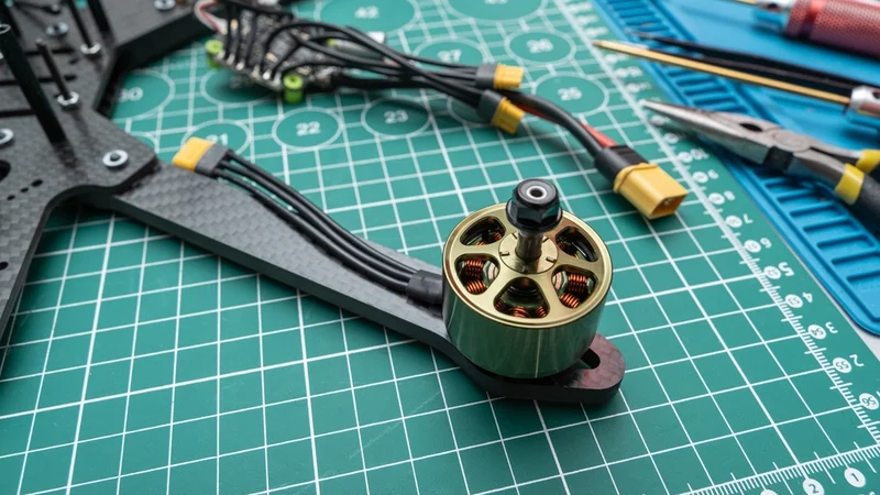
Disassembled Sport FPV Drone Bodies, alongside Engines and Electronic Speed Controllers
Key Takeaways
Speed Control is Integral to all Electric Motors: The goal is to regulate output speed and torque to match load demands while maximizing efficiency. Methods range from adjusting armature voltage in brushed DC machines to V/f control and vector control in AC induction systems.
Open-Loop and Closed-Loop Control Differ in Feedback Usage: Open-loop methods send commands without measuring actual speed; they are simple and cost-effective but less accurate. Closed-loop schemes use sensors such as encoders, resolvers or Hall sensors to monitor rotor position and current, enabling precise speed regulation and dynamic response.
Torque-Speed Curves Guide Controller Design: DC motors exhibit a linear decrease in torque as speed increases, while induction motors show low starting torque and a peak near synchronous speed. Understanding these curves helps engineers choose appropriate control methods.
PWM Frequency, Duty Cycle and Switching Components affect Performance and EMI: Higher PWM frequencies reduce audible noise but increase switching losses. Proper dead-time insertion and gate driver selection are critical to prevent shoot-through and meet EMC requirements.
Field-Oriented Control Decouples Torque and Flux: FOC uses Clarke and Park transforms to express three-phase currents in a rotating reference frame and employs PI loops to regulate d-axis and q-axis currents. This results in high efficiency and low torque ripple in synchronous, PMSM and induction machines.
Device Selection and Proper Tuning Matters: Choosing suitable microcontrollers (TI C2000, STM32) and drivers (DRV8871, DRV8323, TMC2209) and correctly tuning PI/PID controllers, dead-time and current sensing can drastically improve motor performance.
Introduction
The electric motors convert electrical energy into mechanical movement and are universal in modern machines, from robotic arms and electric vehicles to HVAC blowers and CNC tools. Regardless of motor type, controlling the rotational speed and torque is crucial. The ability to regulate speed not only ensures the desired performance but also enhances efficiency, reduces wear and saves energy.
Motor Speed Control involves adjusting the electrical input or using control algorithms to achieve a targeted output. Depending on the application, speed can be controlled through voltage variation, pulse-width modulation, frequency adjustment, feedback loops, or sophisticated drive algorithms. Understanding motor speed control across motor types helps designers select the right driver, sensor, and control strategy for stable and predictable motion. This article explores key motor speed control methods, their operating principles, and practical considerations for real-world motor-driven systems.
Fundamentals of Motor Speed Control
Open-Loop vs Closed-Loop Control
Open-Loop Control applies a predetermined voltage or frequency without measuring the actual speed. In AC motors, this approach often follows a constant volts-per-hertz ratio; the reference mechanical speed determines the inverter frequency and voltage. Because there is no feedback, open-loop systems cannot correct for load changes or disturbances. They are suitable for applications where dynamic response is less critical or cost constraints outweigh precision, such as basic fans or pumps.
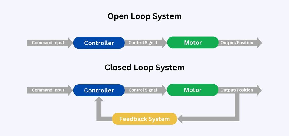
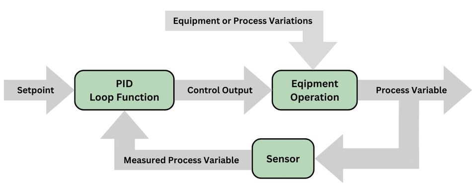
Closed-Loop Control introduces feedback sensors or observers to measure rotor position, speed or current. The position sensors like quadrature encoders, resolvers and Hall-effect devices provide real-time rotor angle, while analog-to-digital converters sample phase currents [1]. The controller compares measured values to setpoints and adjusts the drive signals to minimize error. The closed-loop systems offer better accuracy, faster response and the ability to compensate for changing loads or supply voltages.
Torque-Speed Curves
Understanding a torque-speed characteristic of a motor is vital for selecting and tuning a control method.
DC Motors: Torque decreases linearly as speed increases; maximum torque occurs at stall and drops to zero at no-load speed. Power output peaks at around half of maximum speed.
Universal Motors: Follow a steeper, inverse square relationship, delivering relatively high starting torque but requiring careful control at high speeds.
Induction Motors: Present a different curve: starting torque is low, and torque peaks just below synchronous speed because slip (the difference between synchronous speed and rotor speed) induces rotor currents that produce torque. The slip increases with load; typical full-load slip ranges from less than 1 percent in large motors to 5-6 percent in small machines [2].
Synchronous and Permanent Magnet Synchronous Motors (PMSM): Maintain a constant speed equal to the synchronous speed dictated by supply frequency, so their torque-speed curve is flat until saturation.
Sensors for Feedback Control
The choice of feedback device affects cost, accuracy and robustness.
Hall Sensors: Detect magnetic fields from rotor magnets and provide coarse commutation signals; three sensors at 120-degree intervals output digital signals (U, V and W) used to energize the correct stator windings [3]. They enable basic speed control and are common in cost-sensitive BLDC fans, pumps and power tools.
Incremental Encoders: Use optical or magnetoresistive gratings to generate two quadrature pulse trains and an index pulse. They deliver high resolution (hundreds to tens of thousands of pulses per revolution) for precise measurement of angular displacement, speed and direction.
Encoders: Preferred for servo systems, robotics and CNC machines requiring tight position or speed control.
Recommended Reading: PID Controller & Loops: A Comprehensive Guide to Understanding and Implementation
DC Motor Speed Control
Armature Voltage and Field Control
The basic DC motor speed equation shows that motor speed depends on the relationship between back EMF and magnetic flux. Therefore, speed can be controlled by adjusting either the armature voltage or the field flux.
In armature voltage control, the supply voltage applied to the armature is varied using a controlled power supply, DC drive, or traditional Ward-Leonard system. Increasing the armature voltage raises motor speed while maintaining strong torque performance. This method is suitable for applications that require smooth control and high torque at lower speeds.
In field control, also known as field weakening method, the field current is reduced using a rheostat or electronic controller. This weakens the magnetic flux and allows the motor to operate above its rated speed. However, this comes with reduced torque capability. Series resistance control can also reduce speed, but it wastes energy as heat, making it less efficient than modern voltage-control methods.
PWM Duty Cycle and H-Bridge Drivers
Modern DC motor control uses pulse-width modulation (PWM) to vary the average voltage applied to the motor. By switching the supply on and off at high frequency and adjusting the duty cycle, the controller achieves smooth speed control without the losses of series resistors. Typical PWM frequencies for DC motors range from 1 kHz to 20 kHz; lower frequencies (50-500 Hz) work for high-inertia actuators but can produce audible noise, while higher frequencies reduce acoustic emissions but increase switching losses. When frequencies exceed 20 kHz, the switching is ultrasonic, eliminating audible noise but requiring careful thermal design. [4]
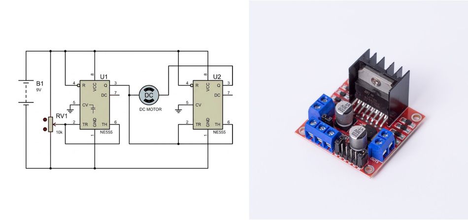
H-Bridge enables bidirectional control by using four switches (MOSFETs or IGBTs) to apply positive or negative voltage across the motor. Integrated drivers such as the Texas Instruments DRV8871 or Allegro A4950 include gate drivers, current regulation and fault protection, simplifying design. Dead-time between switching devices prevents shoot-through; advanced drivers like the Microchip MIC4606 feature adaptive dead-time control and shoot-through protection, monitoring both sides of the bridge to minimize dead-time and improve efficiency.
Current and Thermal Considerations
Closed-loop speed control often uses current feedback to maintain torque while limiting current to protect the motor and driver. The accurate current sensing (via shunt resistors or Hall sensors) ensures correct torque control. Thermal considerations include selecting motors and drivers with adequate continuous current ratings and using heat sinks or cooling to dissipate losses, especially at high PWM frequencies.
Recommended Reading: H Bridge Motor Driver: Complete Engineering Guide to Topologies, ICs, and PCB Layout (2026)
Brushed vs Brushless DC Speed Control
 Brushless vs Brushed DC Motor
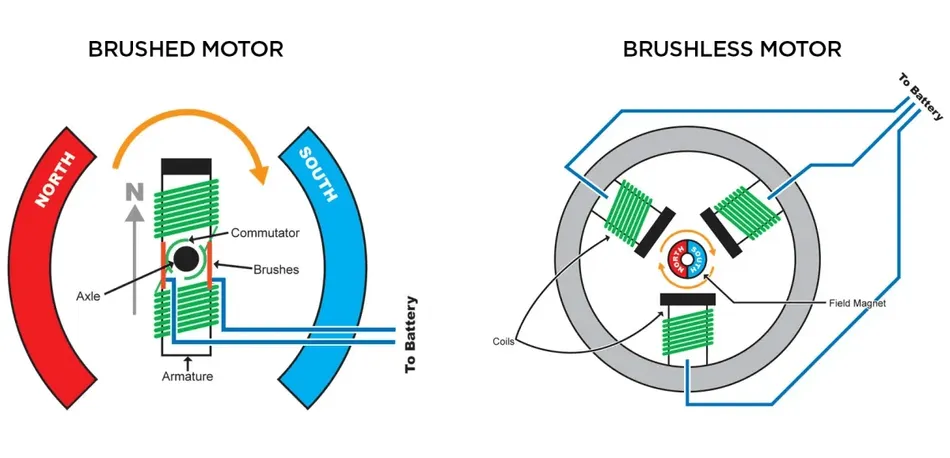
Brushed DC Motors
Brushed motors use mechanical commutation: brushes and a segmented commutator reverse current in the armature windings. Controlling speed involves varying the applied voltage or using PWM with an H-bridge. Brushed motors are simple and provide high starting torque but suffer from brush wear, sparking and maintenance.
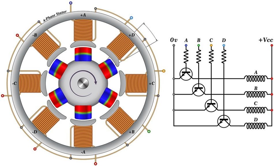
Brushless DC Motors (BLDC)
BLDC motors eliminate brushes by using electronic commutation. They typically employ permanent magnets on the rotor and three-phase stator windings. Speed control involves adjusting the commutation rate and duty cycle of the phase currents.
Six-Step (Trapezoidal) Control
Six-step or trapezoidal control energizes two phases at a time in a six-step sequence. It is easy to implement and delivers high maximum speed with good torque and low switching losses. The stepwise excitation produces torque ripple and audible noise. Hall sensors are often used to detect commutation points and ensure correct phase alignment.
Sinusoidal Control
Sinusoidal commutation applies sinusoidal current waveforms to the three phases, reducing torque ripple and noise. It is sometimes called 180-degree control and still uses a lookup table to generate the currents. Sinusoidal control offers smoother operation but incurs higher switching losses and may reduce dynamic performance, and maximum speed is lower than with six-step control.
Field-Oriented Control (FOC) for BLDC
FOC treats BLDC motors like permanent magnet synchronous machines and controls the stator currents in a rotating d-q reference frame using Clarke and Park transforms.
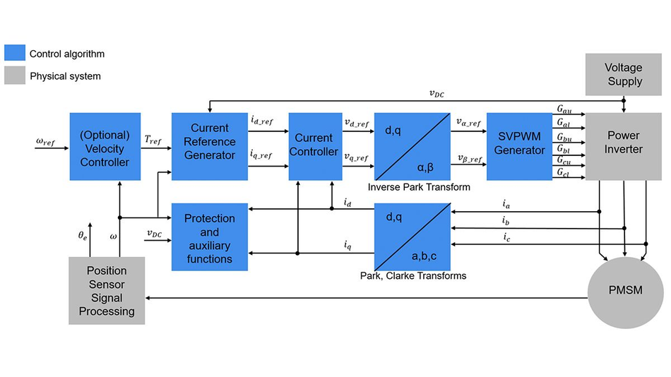
By decoupling the torque (q-axis) and flux-producing (d-axis) currents, FOC provides the highest power output, lowest torque ripple, and highest efficiency. It supports field weakening for speeds above the base frequency and achieves efficiencies up to 97 percent.
BLDC Driver ICs
Common BLDC driver ICs include the TI DRV8323 (three-phase gate driver with smart gate control and FOC support) and STMicroelectronics L6234 (triple half-bridge driver). These devices offer protection features, dead-time control and current sensing to facilitate closed-loop speed control.
Recommended Reading: Brushless vs Brushed Motor: Engineering Trade-offs and Design Decisions
AC Induction Motor Speed Control
Induction motors induce currents into the rotor via a rotating magnetic field.
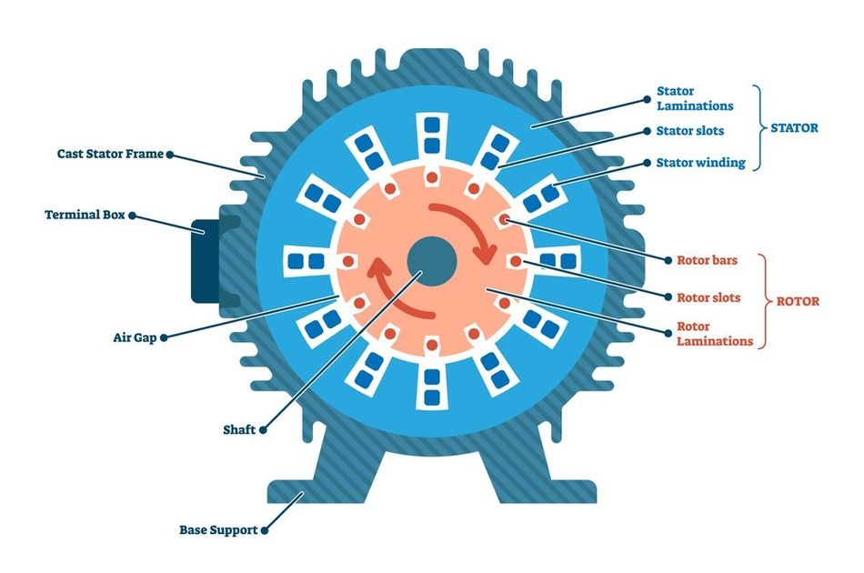
Their speed is slightly below the synchronous speed defined by the supply frequency and number of pole pairs. Here, slip is necessary to generate torque and increase with load.
Variable-Frequency Drives (VFDs) and V/f Control
VFD rectifies AC to DC and inverts it back to AC at a variable frequency. The simplest control is scalar or V/f control, which keeps the stator voltage proportional to frequency to maintain constant flux. In an open-loop configuration, the controller computes the reference voltage magnitude and frequency from the desired mechanical speed and the V/f ratio.
VFDs maintain a constant volts-per-hertz ratio in the constant-torque region; if the ratio is too low, the motor cannot produce sufficient torque, while too high a ratio saturates the core and wastes energy. At speeds above the base frequency, the voltage cannot increase further, so the flux weakens and the the torque capability decreases.
Vector Control (FOC) of Induction Motors
Induction motors can be controlled using FOC. The technique transforms three-phase stator currents to d-q components using Clarke and Park transforms. PI controllers regulate these currents to decouple torque and flux. FOC ensures fast dynamic response and high efficiency, and slip speed can be estimated to align the rotating reference frame. Sensorless observers and sliding-mode observers can estimate rotor position and slip without mechanical sensors.
Synchronous and PMSM Motor Speed Control
Synchronous motors operate at the exact synchronous speed determined by supply frequency.
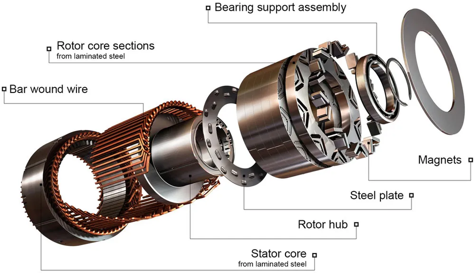
PMSMs are widely used in electric vehicles, robotics and servo applications because they offer high efficiency and power density.
Field-Oriented Control for PMSM
FOC is the primary method for PMSM speed control. Currents are transformed to the rotating reference frame, and PI controllers regulate d- and q-axis currents. The d-axis current is typically set to zero or negative for field weakening; the q-axis current controls torque. FOC reduces torque ripple and enables precise speed control across a wide range [1]. Sensor feedback from encoders or resolvers provides rotor angle; sensorless estimators and sliding-mode observers can infer position from back-EMF and reduce cost.
Sensorless Techniques
Back-EMF is weak at low speeds, so sensorless FOC may start in open-loop or use high-frequency injection. Once the motor reaches about 10 percent of base speed, the estimator locks onto the rotor position and transitions to closed-loop control [1].
Stepper Motor Speed Control
Stepper motors move in discrete steps and are often driven open-loop.
Speed is controlled by adjusting the step rate. To improve smoothness and reduce vibrations, microstepping divides each full step into many smaller microsteps.
Open-Loop Step Rate
In basic stepper control, the controller issues step pulses at a fixed rate. Increasing the pulse frequency increases speed. Once the speed increases, the torque decreases because the inductance limits current buildup.
Microstepping
Microstepping applies sine and cosine current waveforms to the two phases, producing intermediate positions between full steps. Mismatches between the sine and cosine currents cause uneven microstep angles and vibrations; high microstepping with precise current matching improves position and speed uniformity.
Drivers such as the TMC2209 interpolate up to 256 microsteps and include features like StealthChop2 for silent operation, SpreadCycle for dynamic current control and StallGuard4 for sensorless stall detection [5]. The DRV8825 board provides adjustable current limiting and supports six microstepping resolutions up to 1/32; it operates from 8.2 V to 45 V with up to ~1.5 A per phase. The A4988 supports up to 1/16 microstepping and up to 1 A per phase.
Closed-Loop Stepper Systems
Some modern stepper drives incorporate encoders or sensorless feedback to maintain position and prevent missed steps. These systems adjust the current based on load, combining stepper simplicity with servo-like behavior.
Servo Motor Speed Control
Servo motors rely on nested control loops to regulate torque, speed and position. The servo drive typically contains three loops: an inner current (torque) loop, a middle velocity loop and an outer position loop. The velocity loop compares commanded and actual speed and uses PI control to drive the error toward zero. The position loop calculates the following error between desired and actual position and often uses a proportional gain.
In cascaded systems, the position loop may include an integral term for steady-state accuracy. Bandwidths must be hierarchical: the current loop must be 5-10× faster than the velocity loop, and the velocity loop must be 5-10× faster than the position loop [7]. Proper tuning ensures stability and minimizes overshoot.
Recommended Reading: Stepper vs Servo Motors: Mastering Motor Selection for Precision Engineering
PWM and Switching Techniques
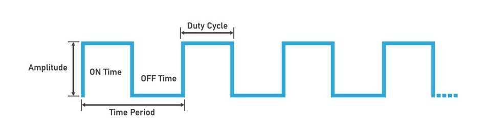
PWM Frequency and Duty Cycle
The pulse-width modulation is the backbone of modern motor drives. Low PWM frequencies (50-500 Hz) suit actuators with high inertia but can cause audible noise, while higher frequencies (1-20 kHz) produce smoother operation and reduce sound. Beyond 20 kHz, switching enters the ultrasonic range, eliminating audible noise but increasing switching losses. To avoid beat frequencies and interference, maintain a consistent PWM frequency across channels.
Dead-Time and Gate Drivers
When using complementary switching devices, dead-time between switching events prevents both devices from conducting simultaneously (shoot-through). Excessive dead-time reduces effective voltage and increases distortion, while insufficient dead-time risks shoot-through. Microchip MIC4606 include adaptive dead-time circuits that monitor the high- and low-side outputs and adjust dead-time dynamically to minimize losses and protect the MOSFETs. Selecting between MOSFETs and IGBTs depends on voltage, current and switching frequency.
Electromagnetic Compatibility (EMC)
EMI reduction techniques include proper PCB layout, twisted-pair or shielded cables, snubber circuits, common-mode chokes and careful grounding. Filtering the PWM outputs and maintaining symmetric current paths help reduce emissions. Drives sold into industrial markets must meet IEC 61800-3 EMC requirements for adjustable speed power drive systems.
Closed-Loop Control Strategies
PI vs PID Control
PID controllers are widely used in speed control. In many motor control applications, PI control suffices because the derivative term can amplify noise and is often unnecessary. PI controllers provide a good balance between speed of response and stability. PID control may be used in the outer position loop of servo systems where mechanical resonances are significant.
Anti-Windup and Feedforward
Once actuators saturate, the integrator in a PI or PID controller can accumulate errors that cause overshoot or sluggish recovery. The anti-windup schemes limit the integrator output to prevent this buildup. Feedforward control adds a model-based term to improve tracking of predictable changes such as expected load torque. Observers (Kalman filters, sliding-mode observers) can estimate unmeasurable states and improve control performance.
Recommended Reading: Mastering PID Tuning: The Comprehensive Guide
Practical Implementation
Microcontroller-Based Control
Texas Instruments C2000 microcontrollers are designed for motor control; they offer 32-bit architecture, high-resolution PWM outputs with timing resolution down to 65 ps, integrated 12.5 MSPS ADCs and programmable dead-time generators.
STM32 microcontrollers (F3, F4 or F7 series) include advanced control timers capable of complementary PWM with dead-time, high-resolution ADCs and hardware quadrature decoder modules.
Hardware PWM timers with dead-time insertion are essential for three-phase BLDC control and microcontrollers like Teensy 4.x or STM32 F4/H7 are well-suited for high-performance FOC.
Dedicated Motor Drive ICs
For brushed DC motors, driver ICs such as TI DRV8871, DRV8848 or Allegro A4950 provide H-bridge switches, current regulation and protection.
For BLDC motors, drivers like DRV8323 or ST L6234 handle three-phase commutation.
The stepper drivers (TMC2209, DRV8825, A4988) integrate microstepping interpolation and current control.
Software and Development Kits
FOC requires software libraries capable of performing Clarke and Park transforms and implementing PI loops. Motor Control SDK and X-CUBE-MCSDK include ready-to-use FOC algorithms, hardware abstraction layers and tuning tools. Open-source projects like SimpleFOC provide simplified FOC implementations for Arduino and STM32.
Gate Drivers and Power Stage Design
The power stage must match motor voltage, current, and switching frequency requirements. MOSFETs or IGBTs should be selected based on conduction losses, switching losses, thermal limits, and voltage margin. Gate drivers with undervoltage lockout, overcurrent protection, and adjustable slew-rate control improve reliability and reduce switching-related failures.
Protection and Fault Handling
Motor drives should include overcurrent, overvoltage, undervoltage, overtemperature, stall, and short-circuit protection. A robust firmware routine must detect faults quickly, disable PWM safely, log error states, and prevent automatic restarts under unsafe conditions. Protection design is especially important in high-power industrial and automotive systems.
Applications
Motor speed control is essential wherever motion must be accurate, efficient, and responsive to changing load conditions. From transportation and factory automation to HVAC systems and precision machining, different motor types require different control strategies.
The following applications show how PWM, VFDs, servo control, vector control, and FOC are used in real-world systems:
Electric Vehicles: FOC for PMSM and induction motors delivers high efficiency and torque density, enabling smooth acceleration and regenerative braking.
Robotics and Automation: Servo drives with nested control loops provide precise motion control for robotic arms, CNC machines and pick-and-place systems.
HVAC Compressors and Blowers: Variable-speed drives adjust compressor and fan speeds to match load demand, improving energy efficiency and comfort.
Conveyors, Pumps and Fans: DC motors with PWM control or induction motors with VFDs offer adjustable throughput; closed-loop ensures constant speed under variable load.
CNC Tools and Machine Spindles: High-speed spindles require precision vector control or sensorless FOC for stable speed across different loads.
Recommended Reading: Powering Electric Motor Drives
Common Pitfalls
Regenerative Braking and Over-Voltage
Once motors decelerate, mechanical energy converts back into electrical energy. If not properly managed, this regenerative current can raise the DC bus voltage and damage components. Solutions include dynamic braking resistors, regenerative drive modules and proper sizing of bulk capacitors.
Thermal Limits and Current Sensing
Operating motors beyond their thermal ratings can cause insulation breakdown and permanent damage. Engineers should select motors with adequate continuous current ratings and implement over-temperature monitoring. Precise current sensing using low-resistance shunts or Hall sensors ensures accurate torque control.
EMI and PCB Layout Issues
High-frequency switching can lead to conducted and radiated emissions. Proper PCB layout with short gate traces, ground planes and decoupling capacitors is crucial. Aligning PWM frequencies and selecting drivers with integrated gate control reduce EMI.
Control Loop Tuning
Poorly tuned PI or PID loops can cause oscillation, overshoot, slow response, or unstable speed control. Engineers should tune current loops first, then speed and position loops. Anti-windup protection, proper sampling rates, and filtering are important for stable response under changing load and speed conditions.
Power Supply Sizing
Undersized power supplies can cause voltage sag, torque loss, controller resets, or unstable motor operation. The supply must handle startup current, peak acceleration current, and regenerative events. Engineers should include voltage margin, adequate bulk capacitance, proper grounding, and protection against inrush current and reverse polarity.
Mechanical Load Mismatch
A motor control system may fail if the motor is not matched to the load. High inertia, sudden load changes, friction, or incorrect gearing can cause overheating, missed steps, vibration, or poor response. Proper motor sizing, gear ratio selection, and acceleration profiling help ensure reliable operation.
Recommended Reading: Speeding Up Motor Drive Design, Testing, and Validation with Nexperia Motor Driver Evaluation Kit
Conclusion
Motor speed control is a multidisciplinary field that combines electromagnetics, power electronics and control theory. Engineers can choose from a variety of techniques, from simple armature voltage variation to sophisticated field-oriented control, depending on motor type, application requirements and budget. Standards such as the IEC 61800 series codify performance and EMC requirements for adjustable speed drives. Advances in microcontrollers and driver ICs make high-performance control accessible across industrial, automotive and consumer products.
Frequently Asked Questions (FAQs)
Q. How do you control motor speed?
A. Motor speed is controlled by changing input voltage, frequency, current, or switching duty cycle. DC motors often use PWM, while AC motors use VFDs. Advanced control systems use feedback sensors to maintain stable speed under changing loads.
Q. What is PWM motor speed control?
A. PWM motor speed control rapidly switches dc power on and off through a transistor or driver circuit. By changing the duty cycle, the average motor voltage changes, allowing efficient speed control without wasting much energy as heat.
Q. How does a VFD control speed?
A. VFD converts incoming AC power into DC and then back into variable-frequency AC. By adjusting frequency and voltage, often measured in VAC, it controls motor speed while keeping torque suitable for pumps, fans, and compressors.
Q. What is the best way to control DC motor speed?
A. For most DC motors, PWM with a suitable driver is the best method. It works well with low voltage systems, supports direction control through polarity switching, and provides efficient speed adjustment for small motors and industrial gearmotors.
Q. Can you control AC motor speed?
A. Yes, AC motor speed can be controlled using VFDs, especially for three-phase motors. These drives regulate voltage and frequency so current flows properly through the windings, improving efficiency in conveyors, blowers, pumps, and refrigerator compressor systems.
Q. How do you control stepper motor speed?
A. Stepper motor speed is controlled by changing the pulse rate sent to the driver. Many NEMA stepper motors use microstepping drivers that regulate phase current in each winding, improving smoothness, reducing vibration, and supporting accurate positioning.
Q. Open-loop vs closed-loop speed control?
A. Open-loop control sends commands without checking actual speed. Closed-loop control uses sensors and feedback to correct errors. Potentiometer may set speed manually, while feedback-based systems adjust drive output when load, amp demand, or torque changes.
References
[1] MathWorks. Open-Loop and Closed-Loop Control of Induction and Synchronous Motors [Cited 2026 May 20]; Available at: Link
[2] Engineering ToolBox. Electrical Induction Motors: Slip [Cited 2026 May 20]; Available at: Link
[3] StepperOnline Help Center. Technical Differences Between Hall Sensors and Incremental Encoders [Cited 2026 May 20]; Available at: Link
[4] Firgelli Automations. PWM Control Guide: Motors, Actuators & Precision Tips [Cited 2026 May 20]; Available at: Link
[5] Analog Devices / Trinamic. TMC2209 Datasheet [Cited 2026 May 20]; Available at: Link
[6] Motion Control Tips. What are Servo Motor Current, Velocity and Position Loops and Bandwidths? [Cited 2026 May 20]; Available at: Link
in this article
1. Key Takeaways2. Introduction3. Fundamentals of Motor Speed Control4. DC Motor Speed Control5. Brushed vs Brushless DC Speed Control6. AC Induction Motor Speed Control7. Synchronous and PMSM Motor Speed Control8. Stepper Motor Speed Control9. Servo Motor Speed Control10. PWM and Switching Techniques11. Closed-Loop Control Strategies12. Practical Implementation13. Applications14. Common Pitfalls15. Conclusion16. Frequently Asked Questions (FAQs)17. References