Field Oriented Control (FOC) for AC Motors
This article explains Field-Oriented Control for AC motors, covering torque, flux, efficiency, and precise variable-speed drive performance.

29 Jun, 2026. 16 minutes read
Field-Oriented Control (FOC); Generated by Gemini
Key Takeaways
Vector Separation Principles – Field Oriented Control, or FOC, is a vector control method that separates AC motor current into flux-producing and torque-producing components.
DC Motor Emulation – FOC makes a PMSM, brushless DC motor, synchronous machine, or induction motor behave more like a separately excited DC machine from a control perspective.
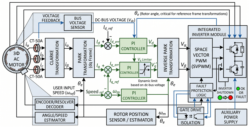
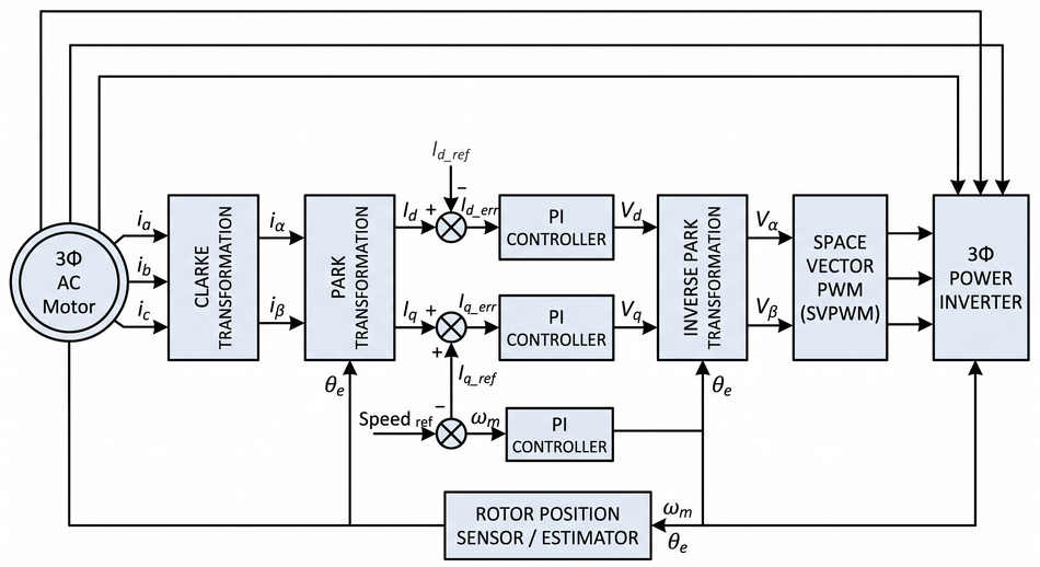
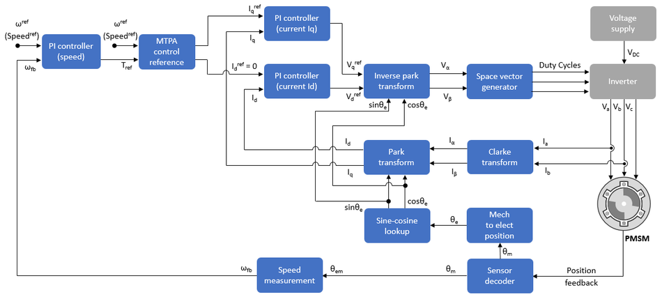
Signal Chain Transformations – The signal chain measures stator currents, applies the Clarke transformation, applies the Park transformation using rotor angle, regulates Id and Iq, applies inverse Park transformations, and drives the power inverter using space vector PWM.
Torque and Flux Channels – Iq is normally the torque command channel, while Id controls magnetic flux, magnetizing current, and field weakening.
Rotor Position Feedback – Rotor position can come from an encoder, resolver, Hall sensors, or sensorless estimation based on a current model, back-EMF, or observer.
Scalar vs Vector Comparison – Compared with scalar volts-per-hertz control, FOC provides better dynamic response, better low-speed torque control, and more efficient high-performance AC drive control, but it requires more computation, sensing, and tuning.
Introduction
Field Oriented Control, or FOC, is an advanced motor control technique that regulates the stator current components in a rotating reference frame aligned with the rotor magnetic flux. It is also called vector control because the controller treats stator voltage, stator current, and magnetic flux as vectors rather than as independent phase quantities. The core idea is simple but powerful: transform sinusoidal phase currents into a rotating reference frame aligned with the motor magnetic field, then control torque and flux as nearly DC quantities.
Field Oriented Control typically relies on current sensors, position or speed feedback, coordinate transformations, and pulse-width modulation to generate optimized inverter switching signals. Modern drives demand higher precision and reliability, so Field Oriented Control has become a key strategy for achieving smooth, responsive, and efficient AC motor operation across variable-speed and servo drive applications in modern systems.
This article is a technical guide to understanding how Field Oriented Control works, why it is used in AC motor drives, and how it supports smooth, responsive, and efficient variable-speed motor operation.
What Field-Oriented Control Does?
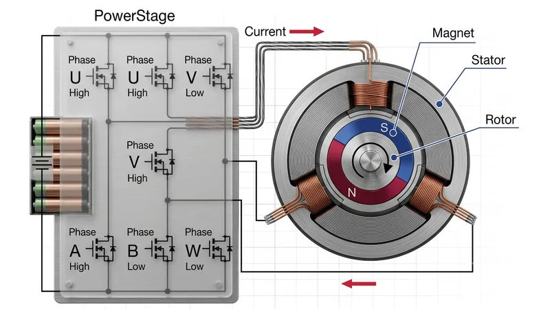
FOC converts a three-phase motor-control problem into a two-axis control problem. In a balanced three-phase AC motor, phase currents ia, ib, and ic create a rotating stator magnetic field. The motor produces torque when that stator field interacts with rotor magnetic flux. [1] In a PMSM, the rotor flux comes mainly from permanent magnets. In induction motors, rotor flux is induced through slip between the stator field and rotor conductors. In wound-field synchronous machines, rotor excitation creates the field.
Without field-oriented control, the controller may command only stator voltage magnitude and frequency, as in scalar V/f control. That can be adequate for fans, pumps, and simple variable-speed drives, but it does not directly control instantaneous torque. FOC instead regulates current vector components in a reference frame that rotates with the rotor flux or another chosen flux vector. The result is independent control of flux and torque.
The practical analogy is a separately excited DC machine. In that machine, field current establishes flux, while armature current controls torque. In FOC, Id plays the flux-related role and Iq plays the torque-producing role. The analogy is not perfect because an AC motor still has inverter limits, sampling delays, motor saliency, back-EMF, temperature variation, dead time, and parameter uncertainty. However, it is the right mental model for understanding why vector control is so effective.
For a surface-mounted PMSM, the usual maximum-torque-per-ampere operating point below base speed is approximately:
Id* = 0
Iq* = torque-producing current command
For an interior PMSM, reluctance torque can be significant because Ld and Lq are different, so the optimal Id may be negative even below base speed. For induction machines, Id is used to establish rotor magnetic flux, while Iq commands torque. For high-speed operation above base speed, Id is often driven negative for field weakening, reducing effective air-gap flux so the inverter can overcome back-EMF within the available DC bus voltage.
Recommended Reading: Motor Control Design: End-to-End Methodology
The FOC Signal Pipeline
The production FOC controller is a deterministic signal pipeline executed every PWM cycle or every current-control interrupt. The exact timing depends on the inverter, ADC, current-sense topology, processor, and switching frequency.
Measure Stator Currents
The controller measures stator currents using shunt resistors, isolated current sensors, or inline current sensors. Three current sensors provide direct measurement of ia, ib, and ic, but many motor control circuits use two shunts because a balanced three-phase motor satisfies:
ia + ib + ic = 0
So the third current can be reconstructed:
ic = -ia - ib
The single-shunt current reconstruction is also possible, but it places tighter constraints on PWM timing and sampling windows. MC SDK documentation by ST lists one-shunt, three-shunt, and isolated-current-sensor topologies among supported current reading options, which reflects the common practical choices in inverter hardware.
The current measurement must be synchronized with pulse width modulation to avoid switching transients. In a center-aligned PWM system, ADC sampling is often placed near the middle of a PWM state where phase current is most stable. Offset calibration, gain calibration, anti-alias filtering, and overcurrent protection are as important as the control law itself.
Clarke Transformation: abc to αβ
The Clarke transformation maps three-phase quantities into a two-axis stationary reference frame. Using the common amplitude-invariant form:
iα = (2/3) (ia - ib/2 - ic/2)
iβ = (2/3) (√3/2) (ib - ic)
i0 = (1/3) (ia + ib + ic)
For a balanced three-wire motor, the zero-sequence term i0 is normally zero. If only two currents are measured and ia + ib + ic = 0, a simplified form is often used:
iα = ia
iβ = (ia + 2ib) / √3
The result is a current vector in the stationary reference frame:
is = iα + j iβ
MathWorks summarizes the same concept: the Clarke transform converts three-phase abc components into two orthogonal components in the stationary αβ frame. [5]
Park Transformation: αβ to d-q
The Park transformation rotates the stationary αβ vector by the electrical rotor angle θe into the rotating reference frame:
id = iα cos(θe) + iβ sin(θe)
iq = -iα sin(θe) + iβ cos(θe)
This is a common sign convention, but code bases vary. Some libraries invert the sign of q, swap axis orientation, or define positive rotation differently. The convention must be consistent across Park transformation, inverse Park transformations, encoder polarity, SVPWM, and current-loop sign.
The rotor angle is electrical, not mechanical:
θe = p θm
ωe = p ωm
where p is the number of pole pairs, θm is mechanical angle, and ωm is mechanical angular speed. One mechanical revolution corresponds to p electrical revolutions, or 360p electrical degrees.
In Park transformation, the balanced sinusoidal currents become nearly constant Id and Iq values when the rotor angle is correct. This is why PI controllers work well in FOC: they regulate DC-like errors rather than sinusoidal phase errors. MathWorks describes the Park transform as converting the αβ frame into an orthogonal rotating dq reference frame, simplifying computations by turning AC waveforms into DC signals. [5]
d-q Current Control with PI Controllers
The current controller compares measured Id and Iq with references:
ed = Id* - Id
eq = Iq* - Iq
The PI controllers generate voltage commands:
Vd* = Kpd ed + Kid ∫ ed dt
Vq* = Kpq eq + Kiq ∫ eq dt
In a basic PMSM drive, Id* may be zero and Iq* comes from the torque command or speed controller. In a cascaded servo structure, the outer position loop generates a speed command, the speed loop generates an Iq torque command, and the inner current loop regulates Id and Iq.
Production implementations usually add decoupling and feed-forward terms. For a PMSM, the d-q voltage model is commonly written as:
Vd = Rs Id + Ld dId/dt - ωe Lq Iq
Vq = Rs Iq + Lq dIq/dt + ωe (Ld Id + ψm)
where Rs is stator resistance, Ld and Lq are d and q inductances, ωe is electrical speed, and ψm is permanent-magnet flux linkage. The cross-coupling terms increase with speed, so decoupling becomes more valuable at high rotor speed.
Inverse Park Transformations and SVPWM
The voltage commands Vd* and Vq* must be transformed back into the stationary frame:
Vα = Vd cos(θe) - Vq sin(θe)
Vβ = Vd sin(θe) + Vq cos(θe)
Then the controller converts Vα and Vβ into inverter switching commands. Many FOC drives use space vector modulation, also called space vector PWM or SVPWM, rather than basic sinusoidal PWM. SVPWM treats the inverter as a finite set of switching vectors and synthesizes the requested voltage vector using two adjacent active vectors plus zero-vector time within each PWM period.
For a two-level three-phase power inverter, SVPWM improves DC bus utilization compared with simple sinusoidal PWM and gives deterministic switching states that are convenient for current sampling. TMS320F2837x PMSM FOC application report states that the sinusoidal voltage waveform is created using the space vector modulation technique.
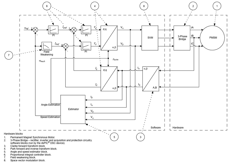
AN1292 block diagram also places Clarke transform, Park forward and inverse transform, PI control, field weakening, and space vector modulation in the sensorless FOC control scheme. [4]
Recommended Reading: DC Motor Speed Control: PWM Techniques for Brushed and BLDC Drives
Torque, Magnetic Flux, and Speed in the d-q Frame
The main engineering value of field-oriented control is that motor torque can be commanded through Iq, while magnetic flux can be managed through Id.
For a PMSM, electromagnetic torque is commonly modeled as:
Te = (3/2) p [ ψm Iq + (Ld - Lq) Id Iq ]
where:
Te = electromagnetic torque
p = pole pairs
ψm = permanent-magnet flux linkage
Ld = d-axis inductance
Lq = q-axis inductance
Id = d-axis current
Iq = q-axis current
For a surface PMSM, Ld ≈ Lq, so reluctance torque is small and the equation reduces to:
Te ≈ (3/2) p ψm Iq
That is why Iq is often described as the torque control channel. For an interior PMSM, Ld and Lq can differ substantially, so reluctance torque contributes to total torque. Maximum torque per ampere control may then command a negative Id even below base speed.
For synchronous machines, the rotor magnetic field rotates at synchronous speed with the stator field. For a motor with P poles and electrical frequency fe, synchronous speed is:
ns = 120 fe / P rpm
or, using pole pairs:
ns = 60 fe / p rpm
The PMSM rotor must remain synchronized with the rotating stator field. Microchip notes that for a PMSM, the rotor field speed must equal the stator field speed, and loss of synchronization causes the motor to halt.
For induction motors, the rotor does not normally turn at synchronous speed. Torque requires slip, meaning the rotor speed is slightly below synchronous speed in motoring operation. In rotor-flux-oriented induction motor control, the controller estimates rotor magnetic flux and aligns the d-axis with it. A simplified steady-state relationship is:
Te = (3/2) p (Lm / Lr) ψr Iq
where Lm is magnetizing inductance, Lr is rotor inductance, and ψr is rotor flux linkage. The slip angular frequency is often estimated from motor parameters and current commands:
ωsl = (Rr Lm / Lr) (Iq / ψr)
The current model for rotor flux may be expressed as:
dψr/dt = (Lm / Tr) Id - (1 / Tr) ψr
Tr = Lr / Rr
This is why induction machines require additional magnetic flux estimation and slip compensation compared with PMSM drives. The controller must know or adapt rotor resistance, which varies with temperature, and must maintain magnetizing current. FOC for induction motors is still highly effective, but the estimator and commissioning process are more involved than for a permanent-magnet synchronous motor.
Recommended Reading: Motor Speed Control: Methods Across Motor Types
Rotor Position, Encoder Feedback, and Sensorless Estimation
FOC needs the electrical rotor angle. If θe is wrong, the Park transformation projects current onto the wrong axes. The result can be reduced torque, current-loop instability, excess heating, vibration, poor field weakening, or failure to start.

The most direct solution is a rotor position sensor. The common choices include:
| Feedback Device | Typical Use | Advantages | Design Considerations |
| Incremental Encoder | Servo Drives, Robotics, CNC | High Resolution, Good Low-Speed Control | Needs Index or Alignment Routine for Absolute Electrical Angle |
| Absolute Encoder | High-end Servo and Safety-Critical Axes | Known Position at | Cost, Protocol Support, EMC Robustness |
| Resolver | Industrial Drives, Harsh Environments | Rugged, Tolerant of Heat and Contamination | Requires Excitation and Resolver-to-Digital Conversion |
| Hall Sensors | BLDC Motor Drives, Fans, Pumps | Low Cost, Simple Commutation | Coarse Angle Resolution, Torque Ripple unless Interpolated |
| Sensorless Observer | Appliances, Pumps, Compressors, Fans | Lower Cost, No Shaft Sensor | Weak or Difficult at Zero and Very Low Speed |
The encoder gives accurate rotor position across the speed range, including standstill. That is useful for servo control, high starting torque, and applications where the motor must hold position. The encoder count must be converted into electrical degrees:
θe = p (θencoder - θoffset)
The offset is normally found through an alignment routine or by using an absolute mechanical reference. Direction polarity must be verified because a sign error can make the current loops appear unstable.
Sensorless FOC estimates rotor angle and rotor speed from measured current, commanded voltage, and a motor model. At medium and high speeds, back-EMF contains strong position information. At low speed, back-EMF is small, so sensorless control often needs open-loop startup, high-frequency injection, saliency tracking, or application-specific startup logic. AN1292 by Microchip describes a sensorless PMSM FOC algorithm using a PLL position and speed estimator and field weakening on dsPIC devices. AN1078 by Microchip addresses sensorless FOC for PMSM using a sliding mode observer, also on dsPIC digital signal controllers.
The sensorless methods include:
| Estimator Type | Main Signal Basis | Strengths | Limitations |
| Back-EMF Observer | Voltage and Current Model | Good at Medium and High Speed | Weak at Zero Speed |
Sliding Mode Observer | Discontinuous Observer with Filtering | Robust to Some Parameter Error | Chattering and Filtering Delay Must be Managed |
| PLL Estimator | Estimated Angle Locked to Model Output | Smooth Angle and Speed Estimate | Needs Tuning and Sufficient Signal Quality |
| Current Model | Motor Current and Parameters | Useful for Induction Motor Flux | Sensitive to Resistance and Inductance Drift |
| High-Frequency Injection | Saliency Response | Can work near Zero Speed on Salient Machines | Adds Acoustic, EMI, and Software Complexity |
The practical FOC design often supports both modes: encoder-based control for commissioning and validation, then sensorless operation for cost-sensitive production variants.
Recommended Reading: What is an Encoder: Understanding the Basics and Beyond
Practical Embedded Implementation
A real FOC loop is a real-time embedded system, not just a set of equations. The firmware, hardware, and motor must be designed together.
Hardware Signal Chain
The minimum system includes:
Gate drivers with dead-time control and desaturation or overcurrent protection where appropriate.
DC bus voltage measurement.
Phase current or DC-link current measurement.
Rotor position feedback interface, or enough analog fidelity for sensorless estimation.
Microcontroller, DSP, or digital signal controller with synchronized PWM, ADC triggers, fast interrupt latency, and fault inputs.
PMSM FOC application note for MIMXRT10xx describes both sensor and sensorless speed and position motor-control software, a PMSM parameter identification algorithm, and a hardware platform using the FRDM-MC-LVPMSM board with a three-phase bridge inverter, MOSFET gate driver, current sensing, DC bus sensing, and encoder or Hall interface.
Control Timing
The typical digital implementation follows this sequence inside a PWM-synchronized current interrupt:
Trigger ADC conversions at a defined PWM instant.
Read phase currents and DC bus voltage.
Remove offsets and apply scaling.
Reconstruct missing phase current if using two-shunt sensing.
Apply Clarke transformation.
Obtain rotor angle from an encoder or estimator.
Apply Park transformation.
Run Id and Iq PI controllers.
Apply voltage limiting and anti-windup.
Apply feed-forward decoupling if used.
Apply inverse Park transformations.
Run space vector PWM.
Update PWM compare registers.
Run slower speed, position, thermal, and communication tasks outside the fastest current loop.
The current loop is normally the fastest closed loop. The speed loop is slower, and the position loop, if present, is slower still. That separation preserves current-loop bandwidth and prevents outer-loop commands from destabilizing inner-loop torque control.
Numeric Representation
FOC can be implemented in fixed point or floating point. Older DSPs and digital signal controllers often used fixed-point arithmetic for deterministic speed. Modern Cortex-M microprocessors and C2000 devices may use floating-point units, trigonometric accelerators, lookup tables, or CORDIC-style routines depending on the part. [2]
The important numeric decisions include:
Per-unit scaling for currents, voltages, and speeds.
Saturation limits before inverse transforms.
PI anti-windup when voltage commands exceed the inverter limit.
Sine and cosine accuracy.
ADC offset tracking.
Angle wraparound and electrical degrees conversion.
Consistent sign conventions from current sensors through PWM outputs.
The controller must also handle abnormal conditions: overcurrent, overvoltage, undervoltage, phase loss, stalled rotor, encoder failure, estimator loss of lock, overtemperature, and communication timeout. Compliance is usually evaluated at the drive system level. For adjustable speed electrical power drive systems, IEC 61800-5-1 specifies safety requirements related to electrical, thermal, fire, mechanical, energy, and other hazards for power drive systems and their elements. [6]
Real Implementation Platforms
TI C2000 MCUs are widely used for motor control because they combine real-time control performance, PWM modules, ADC integration, and motor-control software collateral. TMS320F2837x application report presents sensored FOC for a three-phase PMSM and states that C2000 devices can realize precise digital vector control algorithms such as FOC.
STM32 Motor Control SDK is another practical route. It includes a PMSM FOC firmware library and STM32 Motor Control Workbench for configuring firmware parameters through a GUI. [3] ST lists single and dual FOC, current-sensing options, encoder and Hall support, sensorless state observer operation, speed and torque control, flux weakening, MTPA, feed-forward, and real-time communication as features.
dsPIC ecosystem provides application notes and source-code packages for PMSM sensorless FOC, including sliding mode observer and PLL estimator variants. NXP provides FOC reference designs for i.MX RT and other MCU families with motor parameter identification, FreeMASTER tuning, and hardware platform documentation.
Recommended Reading: What Is a VFD (Variable Frequency Drive)? Complete Engineering Guide to VFD Drives (2026)
FOC vs Scalar V/f Control
Scalar V/f control, also called volts-per-hertz control, controls the voltage magnitude and electrical frequency applied to an AC motor. It attempts to keep air-gap flux roughly constant by maintaining a voltage-to-frequency ratio. It is simple, robust, and common in general-purpose VFD applications. However, it does not directly control the stator current vector, rotor flux angle, or instantaneous torque.
Field-Oriented Control is a more advanced vector control method. Instead of controlling only voltage and frequency, FOC controls the stator current vector by separating it into flux-producing and torque-producing components. It uses variables such as Id, Iq, rotor angle, rotor speed, and DC bus voltage to achieve more precise AC drive control. This allows the motor controller to regulate torque directly through Iq and control magnetic flux through Id or estimated rotor flux.
The main difference is response and precision. Scalar V/f control provides indirect torque control, so its dynamic response is slower and less accurate. It is suitable for fans, pumps, conveyors, and other applications where moderate speed regulation is acceptable. FOC provides faster torque control, better low-speed performance, smoother operation, and higher efficiency. With encoder feedback or a reliable estimator, it can deliver strong performance even at low speed or during rapid load changes.
FOC also requires more hardware and computation than scalar V/f control. It depends on current sensors, rotor position feedback or sensorless estimation, Clarke transformation, Park transformation, PI controllers, and pulse width modulation techniques such as space vector PWM. Scalar V/f control is computationally simpler and may not require detailed current feedback in basic drives, which makes it easier to implement and tune.
For induction motors, both methods are used. Scalar V/f control is common in simple VFDs, while FOC provides better performance when flux and slip estimation are required. For PMSM and brushless DC motors, Field-Oriented Control is generally preferred because these machines require accurate rotor position awareness for efficient and smooth torque production.
Use scalar V/f when the application is cost-sensitive, speed regulation requirements are modest, load dynamics are slow, and low-speed torque is not critical. Use FOC when the application needs precise torque control, fast transient response, quiet operation, high efficiency, good low-speed behavior, or accurate speed and position control.
Recommended Reading: Motor Controller: Types, Design Considerations, Control Strategies, and Selection for Engineers
Tuning, Commissioning, and Failure Modes
FOC performance depends heavily on correct commissioning. Most unstable FOC systems fail for practical reasons, not because the theory is wrong.
Below are the practical reasons:
1. Validate Current Sensing: With the inverter disabled, measure ADC offsets. With known currents or low-voltage injection, confirm scaling and polarity. If one current channel is inverted, the Clarke transformation will produce the wrong stator current vector.
2. Validate Rotor Angle: For encoder systems, confirm pole-pair count, electrical offset, direction, and index handling. A 180 electrical degree error reverses the torque-producing direction. The 90 electrical degree error swaps flux and torque axes. Even smaller offsets increase current for a given torque command.
3. Tune PI Controllers in the Correct Order: The Id and Iq current loops are tuned first. Then the speed loop is tuned. Then the position loop is tuned if the system is a servo. Voltage saturation must be handled with anti-windup, otherwise the integrators continue accumulating error after the inverter has reached its physical limit.
4. Validate Field Weakening: Above base speed, the controller may command negative Id to reduce effective magnetic flux and keep the voltage vector inside the available DC bus range. Field weakening must respect current limits, demagnetization limits for permanent magnets, thermal limits, and speed limits of the rotor and load.
5. Validate Behavior across Temperature: Stator resistance changes with winding temperature, magnet flux changes with temperature, and induction motor rotor resistance changes as the rotor heats. Sensorless observers and current models are especially sensitive to parameter drift.
The common symptoms and root causes include:
| Symptom | Likely Causes |
| Motor Vibrates or will Not Start | Wrong Phase Order, Wrong Encoder Polarity, Wrong Electrical Offset |
| Current Rises with Little Torque | d-q Axes Misaligned, Pole-Pair Count Error, Park Sign Convention Mismatch |
| Good High-Speed Operation but Poor Low-Speed Behavior | Sensorless Estimator Lacks Low-Speed Observability, Current Offsets, Friction Model Error |
| Good No-Load Operation but Poor Load Response | Current-Loop Gains too Low, DC Bus Sag, Torque Limit, Speed-Loop Tuning Error |
| Audible Noise | PWM Frequency, Current Ripple, Dead-Time Distortion, Observer Ripple, Mechanical Resonance |
| Overvoltage during Deceleration | Regeneration, Insufficient Braking Path, DC-Link Capacitance or Braking Resistor Limits |
| Loss of Torque above Base Speed | Field Weakening Limits, Voltage Saturation, Back-EMF Margin too Small |
Many motors sold as brushless DC motors can be controlled with FOC when the application benefits from smoother torque, lower acoustic noise, and better efficiency.
Recommended Reading: BLDC Motor Controller: Comprehensive Design Guide for Engineers
Conclusion
Field-oriented control is the core technique behind modern high-performance AC motor drives. By transforming stator currents from the three-phase abc frame into the stationary reference frame and then into the d-q rotating reference frame, FOC separates magnetic field control from torque control. The result is an AC motor controller that can regulate flux and torque in a way that resembles a separately excited DC machine, while retaining the efficiency, power density, and reliability advantages of PMSM, brushless DC motors, synchronous machines, and induction motors.
The complete implementation requires more than Clarke transformation, Park transformation, PI controllers, inverse Park transformations, and space vector PWM. It also requires accurate current measurement, reliable rotor position or rotor angle estimation, well-timed pulse width modulation, robust inverter protection, careful tuning, and a processor platform capable of deterministic real-time control. The future of FOC is moving toward better sensorless startup, online motor-parameter identification, model predictive current control, GaN and SiC inverter switching, integrated functional safety, and automated tuning.
Frequently Asked Questions
Q. What is field-oriented control in simple engineering terms?
A. Field-oriented control is a motor-control method that converts three-phase AC currents into two rotating-axis components: Id and Iq. Id controls magnetic flux, while Iq controls torque, making AC motor behavior easier to regulate.
Q. Why does FOC need rotor position or rotor angle?
A. FOC needs rotor angle to align the current vector with the rotor magnetic field. Without accurate rotor position, the controller cannot correctly separate flux-producing current from torque-producing current in the rotating reference frame.
Q. What is the difference between Clarke transformation and Park transformation?
A. The Clarke transformation converts three-phase abc currents into two stationary αβ components. The Park transformation then rotates those αβ components into the d-q rotating reference frame using electrical rotor angle, allowing independent Id and Iq control.
Q. What does Iq control in FOC?
A. Iq is the torque-producing current component in Field-Oriented Control. In a PMSM, torque is approximately proportional to Iq. In induction motors, Iq also controls torque, while Id maintains the required rotor magnetic flux.
Q. What does Id control in FOC?
A. Id is the flux-axis current component. In surface PMSM drives, Id is often zero below base speed. In induction motors, Id establishes rotor flux. At high speed, negative Id supports field weakening.
Q. Is FOC only for PMSM motors?
A. No. FOC is used with PMSM, brushless DC motors, synchronous machines, and induction motors. The implementation differs by motor type, but the core principle remains vector control of flux and torque in a rotating reference frame.
Q. How does FOC compare with V/f control?
A. V/f control adjusts voltage magnitude and frequency, making it simple for pumps, fans, and basic VFDs. FOC directly controls current vector components, giving faster torque response, better low-speed performance, and higher control accuracy.
Q. What hardware is required to implement FOC?
A. A typical FOC system requires a three-phase power inverter, gate drivers, current sensing, DC bus voltage sensing, a microcontroller or DSP, PWM and ADC synchronization, and rotor position feedback or sensorless estimation.
References
[1] Texas Instruments. Sensored Field Oriented Control of 3-Phase Permanent Magnet Synchronous Motors (TMS320F2837x) [Cited 2026 June 28]; Available at: Link
[2] Texas Instruments. C2000 MCUs - Motor Control [Cited 2026 June 28]; Available at: Link
[3] STMicroelectronics. X-CUBE-MCSDK STM32 Motor Control Software Development Kit [Cited 2026 June 28]; Available at: Link
[4] Microchip. AN1292: Sensorless Field Oriented Control for a PMSM Using a PLL Estimator and Field Weakening [Cited 2026 June 28]; Available at: Link
[5] MathWorks. Clarke and Park Transforms [Cited 2026 June 28]; Available at: Link
[6] IEC. IEC 61800-5-1:2022, Adjustable Speed Electrical Power Drive Systems, Safety Requirements [Cited 2026 June 28]; Available at: Link
in this article
1. Key Takeaways2. Introduction3. What Field-Oriented Control Does?4. The FOC Signal Pipeline5. Torque, Magnetic Flux, and Speed in the d-q Frame6. Rotor Position, Encoder Feedback, and Sensorless Estimation7. Practical Embedded Implementation8. FOC vs Scalar V/f Control9. Tuning, Commissioning, and Failure Modes10. Conclusion11. Frequently Asked Questions12. References