I2C vs SPI: A Comprehensive Comparison and Analysis
This in-depth guide will delve into the fundamentals of I2C and SPI communication protocols, including their working principles, comparative advantages, system configurations, and practical applications in embedded systems and IoT devices.

Last updated on 29 Dec, 2023. 18 minutes read
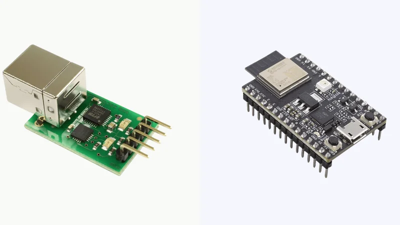
I2C vs SPI Serial Communication Protocol Devices
Introduction to I2C and SPI
I2C and SPI are two of the most common communication protocols used in embedded systems and IoT devices. These protocols are fundamental to operating a wide array of devices, enabling communication between different components within a system.
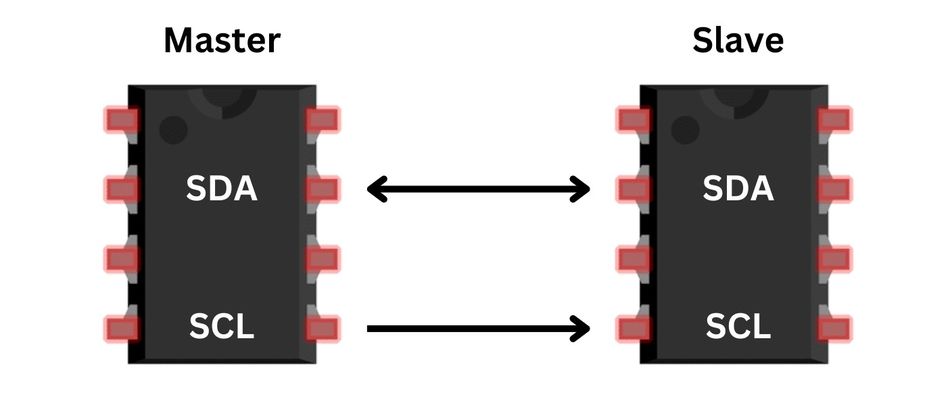
I2C is a multi-master, multi-slave, packet-switched, single-ended, serial communication bus, developed by Philips Semiconductors. It is widely used for attaching lower-speed peripheral ICs to processors and microcontrollers in short-distance, intra-board communication. I2C is a master-slave protocol, where the master device controls the communication, and the slave devices follow the master's instructions.
On the other hand, SPI is a full-duplex synchronous serial communication interface, developed by Motorola. It is a de facto standard, widely used for short-distance communication in embedded systems. Unlike I2C, SPI operates in a master-slave configuration but allows for full-duplex communication, meaning data can be sent and received simultaneously.
I2C vs SPI have their unique strengths and weaknesses. Their suitability for a particular application depends on various factors such as speed requirements, complexity, power consumption, noise immunity, and scalability. Understanding I2C vs SPI protocols and differences is crucial for anyone involved in designing and developing embedded systems and IoT devices.
Understanding I2C
History and Development of I2C
The I2C protocol was developed by Philips Semiconductors, now NXP Semiconductors, in the early 1980s. [1] Its creation was primarily to provide a simple and efficient method for communication between ICs on a PCB. The initial version of I2C supported a maximum data rate of 100 kbps (kilobits per second) and was primarily used for communication between microcontrollers and peripheral devices such as EEPROMs, ADCs, and DACs.
Over the years, I2C has evolved to meet the changing needs of the industry. In 1992, the I2C Fast mode was introduced, increasing the maximum data rate to 400 kbps. Later, in 1998, the High-Speed mode was added, supporting data rates up to 3.4 Mbps (megabits per second). In 2007, the Ultra Fast mode was introduced, allowing for data rates up to 5 Mbps, although this mode is not widely adopted due to its limited range and specific use cases. [2]
Throughout its development, I2C has maintained its core principles of simplicity and efficiency. I2C operates on a master-slave architecture, where one or more master devices control the communication and initiate data transfers, while slave devices respond to the master's requests. Its multi-master, multi-slave architecture allows flexibility in system design and the ability to add or remove devices without disrupting the communication bus. Flash memory is often accessed through I2C, used for storing devices i.e., LCD firmware, configuration data, or user settings.
Working Principle of I2C
The I2C bus consists of two bidirectional lines: the serial data line (SDA) and the serial clock line (SCL). Both lines are open-drain, meaning they can be pulled low by any device on the bus but require pull-up resistors to return to a high state.
The communication process begins when a master device generates a start condition by pulling the SDA line low while the SCL line remains high. The master then sends a 7-bit slave address followed by a read/write bit, indicating whether it wants to read from or write to the slave device. If the addressed slave is present on the bus, it acknowledges the master by pulling the SDA line low during the next clock pulse.
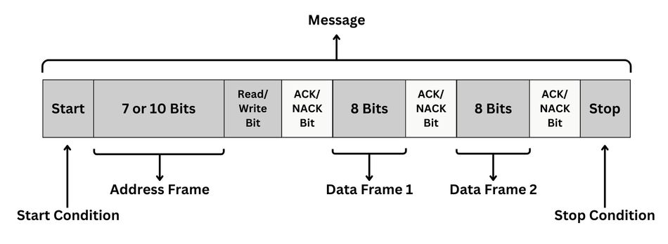
Data transfer occurs in 8-bit units, with the most significant bit (MSB) transmitted first. The master generates the clock pulses on the SCL line, and the data is sampled at the rising edge of each clock pulse. After each 8-bit data byte, the receiving device sends an acknowledgment (ACK) by pulling the SDA line low during the next clock pulse. If the receiving device does not acknowledge, it indicates a NACK (not acknowledged), and the master can either attempt to resend the data or terminate the communication with a stop condition.
A stop condition is generated by the master when it releases the SDA line to go high while the SCL line is high. This signals the end of the communication, and the bus becomes available for other masters to initiate new transactions. Clock Stretching is a mechanism by which a slave device can temporarily hold the clock line low to delay further data transfer, often used to process received data or prepare for the next transaction.
I2C supports multiple masters and slaves on the same bus, allowing for complex system configurations. In a multi-master scenario, arbitration is used to determine which master has control of the bus. Arbitration is based on the wired-AND property of the I2C bus, where any device can pull the bus low, but no single device can force it high. If two masters attempt to transmit in real-time, the one sending a logical '0' will win the arbitration and gain control of the bus.
Key Features of I2C
Two-Wire Interface: One of the main features of I2C is its simple two-wire interface, consisting of the serial data line (SDA) and the serial clock line (SCL). This minimalistic design reduces the number of connections between devices, simplifying the system design and reducing signal interference.
Multi-Master, Multi-Slave Architecture: I2C supports multiple master and slave devices on the same bus, allowing for complex system configurations. This flexibility enables designers to add or remove devices without disrupting the communication bus, making it suitable for a wide range of applications. Chip Select is a signal used to select a specific device on a shared I2C bus.
Arbitration and Clock Synchronization: In a multi-master scenario, I2C uses arbitration to determine which master has control of the bus. This ensures that only one master can initiate communication at a time, preventing data collisions. Additionally, I2C supports clock synchronization, allowing devices with different clock speeds to communicate effectively.
7-bit and 10-bit Addressing: I2C supports both 7-bit and 10-bit addressing, allowing for up to 128 or 1,024 unique device addresses, respectively. [3] This feature enables designers to connect a large number of devices on a single bus, further enhancing the scalability of the system.
Acknowledgment and Error Detection: During data transfer, I2C uses acknowledgment (ACK) and not acknowledgment (NACK) signals to ensure reliable communication between devices. This error detection mechanism helps maintain data integrity and allows the master device to take appropriate action in case of communication errors. Analyzer is used for monitoring, debugging, and troubleshooting I2C communication.
Variable Data Rates: I2C supports various data rates, including Standard mode (100 kbps), Fast mode (400 kbps), Fast mode plus (1 Mbps), and High-Speed mode (3.4 Mbps). This flexibility allows designers to choose the appropriate data rate for their specific application requirements, balancing speed and power consumption.
Low Power Consumption: Due to its simple two-wire interface and relatively low speed, data rates, I2C is known for its low power consumption. This makes it an attractive choice for battery-powered and energy-sensitive applications, such as IoT devices and wearable electronics.
Recommended Reading: Microcontroller-Based IoT Development Kits: Powering the Next Generation of IoT Solutions
Understanding SPI
History and Development of SPI
The Serial Peripheral Interface (SPI) was developed by Motorola in the mid-1980s to facilitate communication between the microcontroller and peripheral devices in an embedded system. [4] The protocol was designed to be simple, efficient, and capable of high-speed data transfers. This makes it ideal for applications requiring rapid data exchange between a microcontroller and one or more peripheral devices.
SPI is a de facto standard, widely accepted and used despite not being an official standard ratified by a standards organization. Over the years, it has been adopted by many semiconductor manufacturers, leading to its widespread use in various applications, from sensor interfacing to data storage and conversion.
The SPI protocol has remained relatively unchanged since its inception, with its simplicity and speed being its main selling points. It operates on a master-slave principle, with the master device controlling the clock and initiating data transfers. The protocol supports full-duplex communication, allowing data to be transmitted and received simultaneously, which can significantly increase the speed of data exchange.
SPI's ability to support high-speed data transfers has made it a popular choice for applications requiring rapid data exchange. It is commonly used in applications such as SD card and TFT display interfacing, where high data rates are essential. Despite the emergence of newer communication protocols, SPI remains a reliable choice for many designers due to its simplicity, speed, and widespread support.
Working Principle of SPI
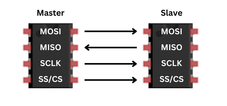
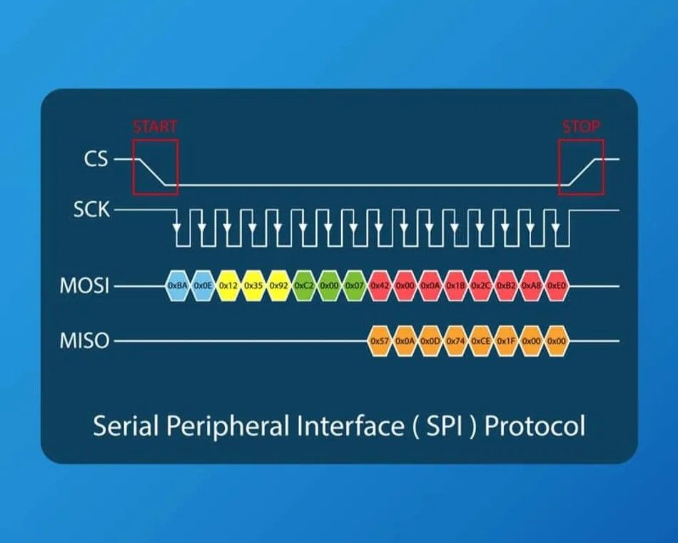
The Serial Peripheral Interface (SPI) operates based on a master-slave architecture, where the master device controls the clock and initiates data transfers. The SPI bus consists of four lines: the serial clock (SCK), master output slave input (MOSI), master input slave output (MISO), and slave select (SS).
The SCLK line is controlled by the master and provides the timing for data transfers. The MOSI line carries data from the master to the slave, while the MISO line carries data from the slave to the master, enabling full-duplex communication. The SS line is used by the master to select the slave device it wants to communicate with. In systems with multiple slave devices, each slave will have its own SS line. [5]
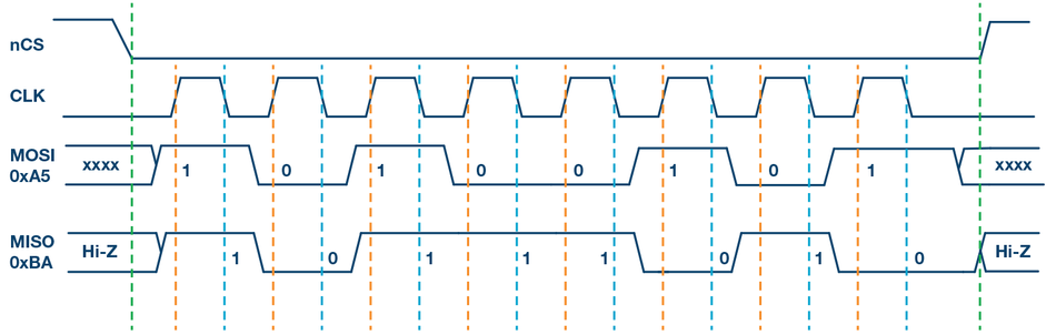
Communication begins when the master pulls the SS line low, selecting the slave device. The master then generates a clock signal on the SCLK line and transmits data on the MOSI line. The data is sampled at the rising or falling edge of the clock signal, depending on the specific SPI mode in use. The slave device simultaneously transmits data on the MISO line, which the master can read.
Data is transferred in 8-bit units, with either the most significant bit (MSB) or the least significant bit (LSB) transmitted first, depending on the SPI mode. After the data transfer is complete, the master pulls the SS line high, deselecting the slave and marking the end of the communication.
SPI does not have a built-in acknowledgment mechanism like I2C. Instead, the successful receipt of data is typically confirmed by the correct operation of the slave device or by a separate handshaking signal.
SPI supports multiple slaves but only one master. However, it is possible to implement multi-master configurations using additional hardware or software mechanisms. Despite its simplicity, SPI's full-duplex communication and high data rates make it a powerful tool for rapid data exchange in embedded systems.
Key Features of SPI
Four-Wire Interface: SPI uses a four-wire interface, which includes the serial clock (SCLK), master out slave in (MOSI), master in slave out (MISO), and slave select (SS) lines. This interface allows for full-duplex communication, enabling simultaneous data transmission and reception.
Master-Slave Architecture: SPI operates based on a master-slave architecture. The single master device controls the clock and initiates data transfers, while the slave devices respond to the master's requests. This architecture allows for straightforward and efficient communication between devices.
Full-Duplex Communication: One of the key features of SPI is its support for full-duplex communication. This means that data can be transmitted and received simultaneously, which can significantly increase the speed of data exchange.
High-Speed Data Transfer: SPI is known for its high-speed data transfer capabilities. [6] While the actual data rate depends on the specific implementation and the master's clock speed, SPI can typically support data rates up to several megabits per second. This makes it suitable for applications requiring rapid data exchange.
No Acknowledgment Mechanism: Unlike other communication protocols, SPI does not have a built-in acknowledgment mechanism. Instead, the successful receipt of data is typically confirmed by the correct operation of the slave device or by a separate handshaking signal.
Multiple Slave Support: SPI supports communication with multiple slave devices. Each slave device has its own SS line, which the master can pull low to select the device for communication. This feature allows for complex system configurations with multiple peripheral devices.
Flexibility: SPI is a flexible protocol that can be used in various applications. It supports different data orders (MSB-first or LSB-first) and clock polarities, and it can be used with a wide range of devices, from sensors and memory chips to displays and digital-to-analog converters.
Recommended Reading: UART vs SPI: A Comprehensive Comparison for Embedded Systems
I2C vs SPI: A Comparative Analysis
Speed
When comparing the speed of I2C and SPI, SPI generally comes out on top. While the I2C protocol supports various data rates, including Standard mode (100 kbps), Fast mode (400 kbps), Fast mode plus (1 Mbps), and High-Speed mode (3.4 Mbps), SPI can typically support data rates up to several Mbps or MHz per second, depending on the specific implementation and the master's clock speed.
The higher data rates of SPI are primarily due to its full-duplex communication capability, which allows data to be transmitted and received simultaneously. This can significantly increase the speed of data exchange, making SPI suitable for applications requiring rapid data transfer.
On the other hand, I2C's slower data rates are partly due to its half-duplex communication, where data can only be transmitted or received at any given time, not simultaneously. Additionally, I2C's transfer speed is also limited by the need for pull-up resistors on the bus lines, which can slow down the rise time of signals and, hence the overall data rate.
However, it's important to note that while SPI can achieve higher transmit data rates, this comes at the cost of increased complexity due to the need for more signal lines (four in SPI vs two in I2C). Therefore, the choice between I2C and SPI will often depend on the specific requirements of the application, including factors such as speed, complexity, and the number of devices to be connected.
Complexity
In terms of complexity, I2C and SPI present different challenges and advantages. I2C's design is inherently simpler, with only two bus select lines required for communication - the serial data line (SDA) and the serial clock line (SCL). This simplicity reduces the number of connections required between devices, simplifying the overall system design and reducing the potential for signal interference. Furthermore, I2C device's built-in acknowledgment mechanism and error detection provide a level of robustness and reliability in communication.
However, I2C's simplicity also comes with limitations. The protocol's multi-master, multi-slave architecture can lead to increased complexity in bus management, particularly in scenarios with multiple master devices. The need for arbitration to determine which master has control of the bus, as well as clock synchronization to allow devices with different clock speeds to communicate effectively, can add to the complexity of implementing I2C.
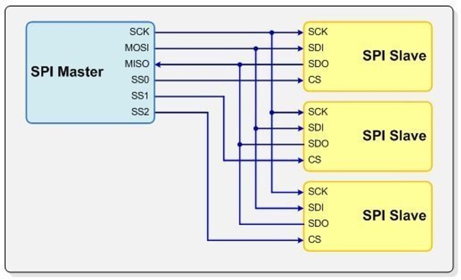
On the other hand, SPI's four-wire interface, which includes the serial clock (SCLK), master output slave input (MOSI), master input slave output (MISO), and slave select (SS) lines, increases the complexity of the physical layer. Each slave device requires a separate SS line, which can lead to a large number of signal lines in systems with multiple slave devices. This can complicate the design and increase the size of the system.
However, SPI's protocol is simpler than I2C's. There is no need for arbitration or clock synchronization, as there is only one master device. Furthermore, the lack of a built-in acknowledgment mechanism simplifies the protocol, although it also places more responsibility on the application to ensure data integrity.
In conclusion, while I2C's protocol is more complex due to its support for multiple masters and built-in error detection, its physical layer is simpler. Conversely, SPI's protocol is simpler, but its physical layer is more complex due to the need for more signal lines. The choice between I2C and SPI devices will depend on the specific requirements of the application, including factors such as the number of devices to be connected, the speed requirements, and the available resources for implementation.
Power Consumption
Power consumption is a critical factor in many applications, particularly in battery-powered devices. Both I2C and SPI have characteristics that can influence power consumption.
I2C's slower data rates can lead to lower power consumption, as slower clock speeds typically result in less power being used. Additionally, I2C's two-wire interface can also contribute to lower power consumption, as fewer signal lines can result in less power being used for driving signals. However, the need for pull-up resistors on the I2C bus can increase power consumption, particularly in high-speed or long-distance applications where stronger pull-ups may be required.
On the other hand, SPI's higher data rates can lead to higher power consumption, as faster clock speeds typically result in more power being used. Furthermore, SPI's four-wire interface can increase power consumption, as more signal lines can result in more power being used for driving signals. However, SPI does not require pull-up resistors, which can reduce power consumption compared to I2C.
It's also worth noting that power consumption can be influenced by other factors, such as the operating voltage, the load on the bus, and the activity level (how often data is being transferred). Therefore, the actual power consumption in a specific application can vary and may not strictly follow the general trends outlined above.
In conclusion, while I2C can potentially offer lower power consumption due to its slower data rates and fewer signal lines, the need for pull-up resistors can increase power consumption. [7] Conversely, while SPI can potentially have higher power consumption due to its faster data rates and more signal lines, the lack of pull-up resistors can reduce power consumption. The choice between I2C and SPI will depend on the specific requirements of the application, including factors such as power consumption, speed requirements, and the complexity of the system.
Noise Immunity
Noise immunity is a critical factor in the design and implementation of communication protocols, particularly in environments with high levels of electromagnetic interference. Both I2C and SPI have characteristics that can influence their noise immunity.
I2C's two-wire interface, with the serial data line (SDA) and the serial clock line (SCL), can be more susceptible to noise due to the shared bus configuration. Noise on the bus can potentially affect all devices connected to it. However, I2C's built-in acknowledgment mechanism can help to mitigate the impact of noise. If a device does not acknowledge a transmission, the master can infer that the data may have been corrupted by noise and can attempt to retransmit the data.
On the other hand, SPI's four-wire interface can provide better noise immunity. The separate lines for data transmission and reception can help to isolate noise and prevent it from affecting the entire system. However, SPI does not have a built-in acknowledgment mechanism like I2C, so it relies more heavily on the physical layer for noise immunity.
In terms of signal integrity, both I2C and SPI can benefit from good PCB design practices, such as proper routing of signal lines, use of decoupling capacitors, and careful selection of pull-up resistors (in the case of I2C).
In conclusion, while I2C's shared bus configuration can make it more susceptible to noise, its built-in acknowledgment mechanism can help to ensure data integrity. Conversely, SPI's separate data lines can provide better noise immunity, but the lack of an acknowledgment mechanism places more responsibility on the physical layer and system design to maintain signal integrity. The choice between I2C and SPI will depend on the specific requirements of the application, including factors such as noise environment, data integrity requirements, and system complexity.
Scalability
Scalability is an important consideration when choosing a communication protocol, as it determines how easily a system can be expanded to accommodate additional devices. Both I2C and SPI have features that can influence their scalability.
I2C's multi-master, multi-slave architecture allows for a large number of devices to be connected to the same bus. With support for both 7-bit and 10-bit addressing, I2C can accommodate up to 128 or 1,024 unique device addresses, respectively. [8] Shift registers enable designers to connect a large number of devices on a single bus, enhancing the scalability of the system. Additionally, the two-wire interface of I2C simplifies the connections between devices, reducing the complexity of adding new devices to the system.
However, I2C's scalability can be limited by factors such as bus capacitance and the need for pull-up resistors, which can affect signal integrity and speed as the number of devices on the bus increases. Furthermore, the shared bus configuration can lead to increased complexity in bus management, particularly in scenarios with multiple master devices.
In contrast, SPI's master-slave architecture and four-wire interface can provide better scalability in terms of data rates, as the protocol supports high-speed data transfers. However, SPI's scalability is limited by the need for a separate slave select (SS) line for each slave device. In systems with multiple slave devices, this can lead to a large number of signal lines, increasing the complexity of the system and making it more difficult to add new devices.
In conclusion, while I2C offers greater scalability in terms of the number of devices that can be connected to a single bus, its scalability can be limited by factors such as bus capacitance and the need for pull-up resistors. On the other hand, SPI provides better scalability in terms of data rates but is limited by the need for a separate SS line for each slave device. The choice between I2C and SPI will depend on the specific requirements of the application, including factors such as the number of devices to be connected, the speed requirements, and the available resources for implementation.
Recommended Reading: SPI vs I2C vs UART: In-Depth Comparison
Choosing Between I2C and SPI
When deciding between I2C and SPI for a specific application, several factors should be considered to determine the most suitable communication protocol. These factors include:
Speed Requirements: If high-speed data transfer is a priority, SPI may be the better choice due to its full-duplex communication and higher data rates. However, if the speed requirements are moderate and other factors such as simplicity and power consumption are more important, I2C may be more suitable.
System Complexity: I2C's two-wire interface and multi-master, multi-slave architecture can simplify system design and reduce the number of connections between devices. However, managing the shared bus and addressing multiple devices can become complex. In contrast, SPI's four-wire interface and master-slave architecture can provide better performance but may increase system complexity due to the need for separate SS lines for each slave device. [9]
Power Consumption: If power consumption is a critical factor, I2C's slower data rates and fewer signal lines can lead to lower power consumption. However, the need for pull-up resistors can sometimes increase power consumption. SPI's higher data rates and additional signal lines can result in higher power consumption, but the lack of pull-up resistors can offset this to some extent.
Noise Immunity: In environments with high levels of electromagnetic interference, SPI's separate data lines can provide better noise immunity than I2C's shared bus configuration. However, I2C's built-in acknowledgment mechanism can help to ensure data integrity in the presence of noise.
Scalability: I2C's support for many devices on a single bus can provide better scalability in terms of device count. However, its scalability can be limited by factors such as bus capacitance and the need for pull-up resistors. SPI's scalability is limited by the need for a separate SS line for each slave device but can provide better scalability in terms of data rates.
Ultimately, the choice between I2C and SPI will depend on the specific requirements of the application and the trade-offs between factors such as speed, complexity, power consumption, noise immunity, and scalability. By carefully considering these factors, designers can select the most appropriate communication protocol for their system.
Conclusion
In summary, both I2C and SPI are widely used communication protocols in embedded systems and IoT devices, each with its own set of advantages and limitations. I2C offers a simpler two-wire interface and multi-master, multi-slave architecture, making it suitable for applications with moderate speed requirements and a focus on simplicity and power consumption. On the other hand, SPI provides higher data rates and full-duplex communication, making it ideal for applications requiring rapid data exchange. The choice between I2C and SPI depends on the specific requirements of the application, including factors such as speed, complexity, power consumption, noise immunity, and scalability.
FAQs
Q: What is the main difference between I2C and SPI?
A: The main difference between I2C and SPI is their communication interface and architecture. I2C uses a two-wire interface with a multi-master, multi-slave architecture, while SPI uses a four-wire interface with a master-slave architecture.
Q: Can I use both I2C and SPI in the same system?
A: Yes, it is possible to use both I2C and SPI in the same system if the application requires the advantages of both protocols. Many microcontrollers support both I2C and SPI interfaces, allowing designers to choose the most appropriate protocol for each peripheral device.
Q: How can I improve the noise immunity of I2C and SPI?
A: Noise immunity can be improved by following good PCB design practices, such as proper routing of signal lines, using decoupling capacitors, and careful selection of pull-up resistors (in the case of I2C). Additionally, using shielded cables or differential signaling can help reduce the impact of noise on the communication lines.
Q: Are there any alternatives to I2C and SPI for embedded systems communication?
A: Yes, there are several alternatives to I2C and SPI, such as UART (Universal Asynchronous Receiver/Transmitter), CAN (Controller Area Network), and USB (Universal Serial Bus). The choice of communication protocol depends on the specific requirements of the application, including factors such as speed, complexity, power consumption, and noise immunity.
References
[1] Kevsrobots. UNDERSTANDING I²C (INTER-INTEGRATED CIRCUIT): HOW IT WORKS [Cited 2023 December 22] Available at: Link
[2] Analog. Proven Implementations of the I²C Bus [Cited 2023 December 22] Available at: Link
[3] Microchip. Using the PIC Devices’ SSP and MSSP Modules for Slave I2CTM Communication [Cited 2023 December 22] Available at: Link
[4] TechTarget. Serial Peripheral Interface (SPI) [Cited 2023 December 22] Available at: Link
[5] Circuitbasics. BASICS OF THE SPI COMMUNICATION PROTOCOL [Cited 2023 December 22] Available at: Link
[6] Justdoelectronics. Understand SPI Communication Protocol [Cited 2023 December 22] Available at: Link
[7] Arrow. SPI vs I2C Protocols - Pros and Cons [Cited 2023 December 22] Available at: Link
[8] Totalphase. 7-bit 8-bit and 10-bit I2C Slave Addressing [Cited 2023 December 22] Available at: Link
[9] Evision-webshop. I2C vs SPI Protocol: Differences and Similarities [Cited 2023 December 22] Available at: Link