Arduino UNO Pinout: Comprehensive Guide for Engineers and Students
This article covers every aspect of the Arduino UNO pinout, presenting a technical, pin-by-pin explanation to help readers confidently design, analyze, and implement Arduino-based systems.

20 Jan, 2026. 16 minutes read
Key Takeaways
Complete Pin Overview – The Arduino UNO board has 14 digital input/output pins (6 with PWM capability), and 6 analog input channels. The function, electrical limits and special features of each pin are explained with tables and diagrams.
Microcontroller Internals – The guide details the memory architecture, I/O registers, timers and 10‑bit ADC of ATmega328P, so engineers understand how the hardware works.
Power and Communication – Learn the recommended supply options (USB, VIN and barrel jack), current limits, voltage reference pins and how to use UART, SPI and I²C interfaces for sensor and peripheral integration.
Practical Examples – Code snippets demonstrate how to toggle digital outputs, read analog voltages, generate PWM signals, configure interrupts and communicate over I²C.
Design Advice – Best practices for current limiting, level shifting, shielding, and debugging help you build safe and reliable circuits with the Arduino UNO.
Introduction
Arduino UNO is one of the most widely used development boards in embedded systems, serving as a standard platform in education, research, and rapid prototyping. Understanding the Arduino UNO pinout is essential for designing reliable circuits, selecting appropriate peripherals, and ensuring correct electrical connections during prototyping and production. It provides a clear overview of digital I/O pins, analog inputs, power pins, communication interfaces, and special-purpose signals, enabling precise hardware-level control.
For embedded systems engineers, the Arduino UNO pinout helps translate software logic into accurate physical connections, reducing debugging time and preventing common wiring errors. Students and beginners benefit from its structured layout, which simplifies learning core concepts such as GPIO operation, PWM control, ADC usage, and serial communication. Additionally, a detailed understanding of the Arduino UNO pinout supports advanced applications, including sensor integration, actuator control, and interface expansion using shields and external modules.
This guide presents a technical, pin-by-pin explanation to help readers confidently design, analyze, and implement Arduino-based systems.
Overview of the Arduino UNO Board
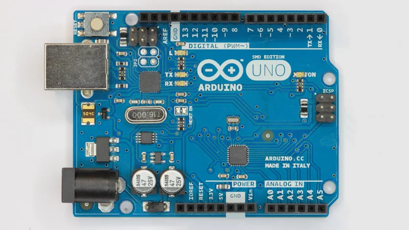
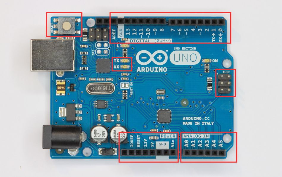
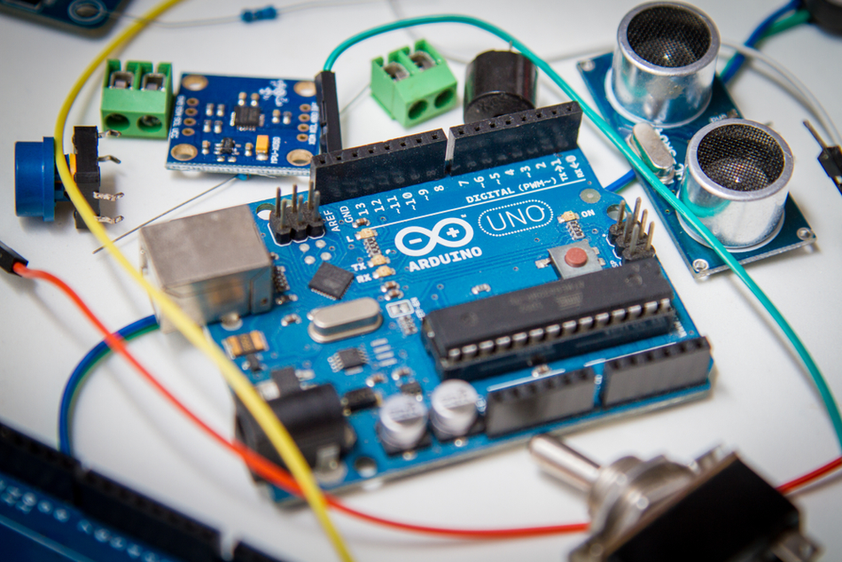
The UNO is part of the classic Arduino board family. The current revision (UNO Rev3) uses the ATmega328P microcontroller running at 16 MHz and exposes its I/O pins through convenient headers. The board includes 14 digital input/output pins, 6 analog inputs, a 16 MHz ceramic resonator, a USB connection, a power jack, an ICSP header and a reset button [1]. These features allow users to connect the board to a computer via USB cable or power it from an external source and immediately begin experimenting.
The table below summarizes the technical characteristics of the UNO Rev3, highlighting the features most relevant to pin selection. The microcontroller uses 5 V logic, and the recommended input voltage range is 7 V to 12 V.
Specification | Value | Notes |
Microcontroller | ATmega328P | 8‑bit AVR RISC Core with 32 KB Flash, 2 KB SRAM, 1 KB EEPROM |
Operating Voltage | 5 V | Logic Levels at Pins are Referenced to 5 V |
Input Voltage | 7–12 V | Supplied via Barrel Jack or VIN Pin; Absolute Range 6–20 V |
Digital I/O Pins | 14 (0–13) | Six Pins (3, 5, 6, 9, 10, 11) support PWM |
Analog Input Pins | 6 (A0–A5) | 10‑bit ADC providing 0–1023 Digital Values |
DC Current per I/O Pin | 20 mA | Absolute Maximum 40 mA; Total across all Pins not to exceed ~200 mA |
DC Current for 3.3 V Pin | 50 mA | Provided by Onboard Regulator |
Clock Speed | 16 MHz | Sourced from Ceramic Resonator |
Communication Interfaces | UART, SPI, I²C | Exposed on Digital Pins and ICSP Header |
Dimensions | 68.6 × 53.4 mm | Compact Layout Fits Standard Shield Footprint |
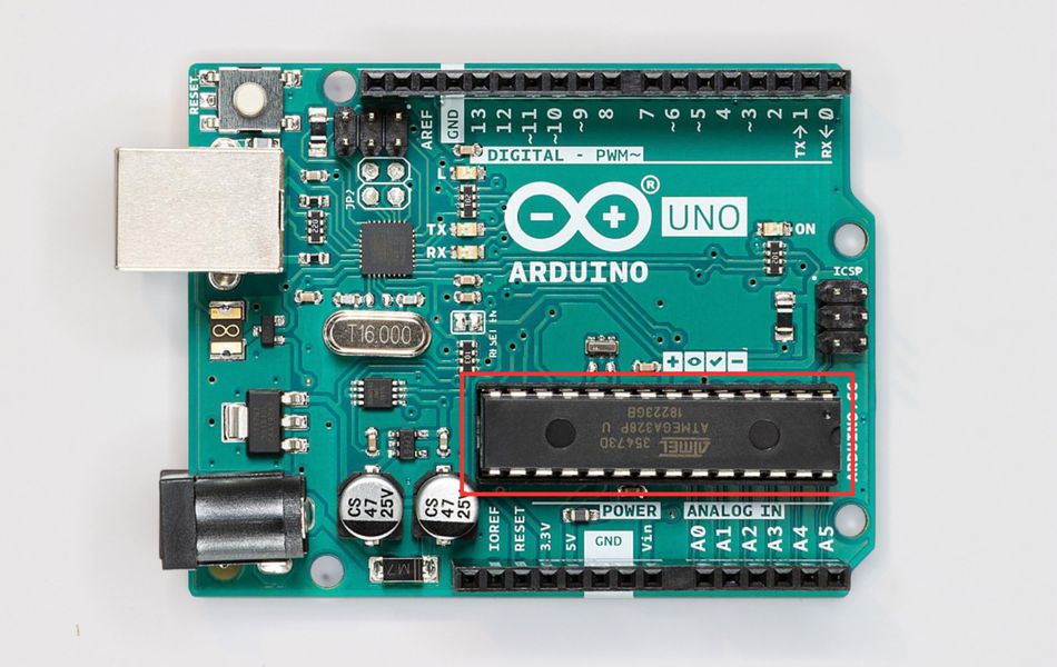
The ATmega328P Microcontroller
The ATmega328P is an 8‑bit AVR RISC microcontroller with an instruction set optimized for high‑level languages like C/C++. It features 32 KB of flash memory, 2 KB of SRAM and 1 KB of EEPROM. It also contains three timers/counters, a six‑channel 10‑bit ADC, one USART, SPI and I²C interfaces, and 23 programmable I/O lines. Because the UNO board uses only 20 of those pins, the remaining lines are used internally or for power.
The internal architecture maps GPIO functionality across Port B, Port C, and Port D, each controlled through DDRx, PORTx, and PINx registers. This low-level mapping explains how high-level functions such as digitalWrite(), analogReference(), and analogRead() ultimately interact with hardware. [2] PWM signals are generated via timer compare units, while the ADC employs a successive-approximation technique to convert analog input voltages into digital values.
The figure above shows the definitive Arduino UNO Pinout diagram, mapping every header pin to its corresponding ATmega328P pin, internal port, timer association, and alternate function. This pinout diagram is essential for understanding SPI (MOSI, MISO, SCK) routing, UART pins, analog input pins, power pins, and special signals such as AREF and Reset, ensuring correct hardware design and reliable system integration.
Recommended Reading: RISC-V vs ARM: A Comprehensive Comparison of Processor Architectures
Power Supply Pins and Voltage References
Properly powering the UNO is the first step in any project. The board can be powered in three ways: through the USB Connector, via the Barrel Jack, or using the VIN Pin. The barrel jack and VIN pins accept 6–20 V, but the manufacturer recommends 7–12 V to avoid overheating voltage regulators or under‑voltage issues. The USB provides regulated 5 V at up to 500 mA; this current must power the microcontroller and any connected sensors. Once using a high‑current shield or motor, an external supply is preferred.
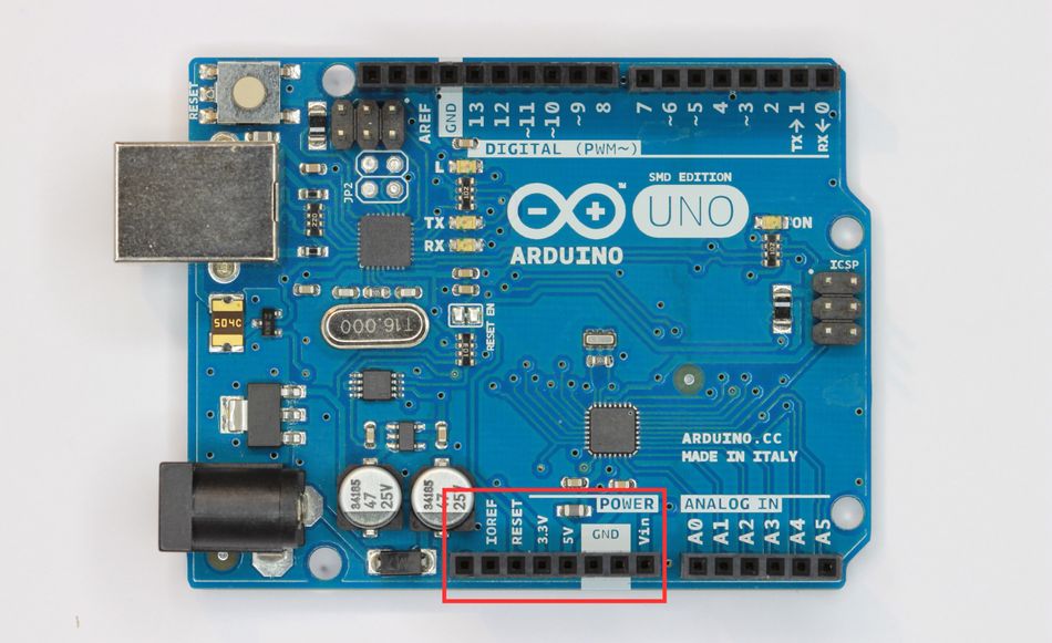
The power header on the UNO contains several necessary pins:
VIN – Input pin for supplying unregulated power. When an external supply is connected to the barrel jack, VIN is connected through a reverse‑polarity diode and can supply external circuits at the same voltage.
5 V – Regulated 5 V output from the onboard regulator or USB. It can power external sensors and modules; however, the total current drawn should remain within the limits of the regulator (approximately 500 mA from USB or ~1 A from a 7–12 V supply).
3.3 V – Regulated 3.3 V output provided by an onboard regulator. The current is limited to 50 mA, so use an external regulator for higher loads.
GND – There are multiple ground pins on the UNO. All ground pins are connected internally and serve as common reference points for circuits. Always connect the ground of external devices to one of these pins.
IOREF – Provides the voltage reference used by the I/O of the microcontroller. For the UNO, this is 5 V, but the pin enables shields to adapt to boards with different logic levels.
RESET – Active‑low input that resets the microcontroller. Short this pin to ground momentarily to restart the program. Many shields bring this signal to a button for convenience.
AREF – Analog reference voltage for the ADC. By default, the ADC uses the 5 V supply on the board, but you can apply an external reference voltage between 0 V and 5 V to the AREF pin via a 5 kΩ resistor to improve accuracy. Do not drive the AREF pin when using the internal reference; otherwise, the microcontroller board may be damaged.
Recommended Supply Practices
Once you design a circuit around the UNO, follow these power‑related guidelines:
Stay within Voltage Limits: Connectors and VIN accept 6–20 V, but 7–12 V is optimal. Below 7 V, the regulator may drop out; above 12 V, it may dissipate excessive heat.
Limit Current Draw: While each I/O pin can source or sink up to 40 mA, the recommended continuous current is 20 mA, and the sum across all I/O pins should not exceed 200 mA.
Use Separate Supplies for High‑Power Loads: Motors and relays can introduce noise and large currents. Power them from a dedicated supply and use transistors or driver ICs to interface with the UNO pins.
Decouple Power Lines: Add 100 nF and 10 µF capacitors near the supply header to smooth transients. For analog measurements, use additional filtering close to the sensors.
Recommended Reading: Microprocessor vs Integrated Circuit: Unveiling the Core of Modern Technology
Digital I/O Pins (0–13)
The UNO provides 14 digital input/output pins numbered 0 through 13. [3] These pins can be configured individually as inputs or outputs using the Arduino pinMode() function. Once configured as outputs, they output either HIGH (5 V) or LOW (0 V); when configured as inputs, they detect logic levels from external circuits. A digital input is considered LOW when the voltage is below 0.8 V and HIGH when it is above 2.0 V. Voltages between these thresholds produce undefined results, so ensure compatibility when interfacing with 3.3 V devices.
Among the digital pins, pins 3, 5, 6, 9, 10 and 11 support pulse‑width modulation (PWM). PWM allows the UNO to generate analog‑like voltages by switching the output between HIGH and LOW at a fixed frequency and varying the duty cycle. The default PWM frequency on the UNO is about 500 Hz. Duty cycles range from 0% (always LOW) to 100% (always HIGH). Applications include dimming LEDs, controlling servo motors and generating audio signals.
Pins 0 and 1 are also used for serial (UART) communication. They connect to the ATmega16U2 USB‑to‑serial converter on the UNO board. When uploading sketches via USB or using the Serial class, avoid connecting other devices to pins 0 and 1.
Pins 2 and 3 support external interrupts labeled INT0 and INT1. Interrupts provide a mechanism to execute code in response to external events such as button presses, encoder pulses or sensor signals. In addition to these external interrupts, the UNO supports pin-change interrupts on any digital pin, though with less flexibility.
The table below summarizes the digital pins, indicating which ones support PWM, UART, SPI and interrupt features:
Board Pin | MCU Port Bit | Special Functions | Typical Uses |
D0 | PD0 | RX (UART) | Serial Receive; cannot be used when Serial is Active |
D1 | PD1 | TX (UART) | Serial Transmit |
D2 | PD2 | INT0, PCINT18 | External Interrupt Input, General Digital I/O |
D3 | PD3 | PWM (Timer2), INT1 | PWM Output, External Interrupt |
D4 | PD4 | PCINT20 | General Digital I/O |
D5 | PD5 | PWM (Timer0) | PWM Output |
D6 | PD6 | PWM (Timer0) | PWM Output |
D7 | PD7 | PCINT23 | General Digital I/O |
D8 | PB0 | PCINT0 | General Digital I/O |
D9 | PB1 | PWM (Timer1) | PWM Output |
D10 | PB2 | PWM (Timer1), SS (SPI) | SPI Slave‑Select, PWM Output |
D11 | PB3 | PWM (Timer2), MOSI (SPI) | SPI Master‑Out, Slave‑In |
D12 | PB4 | MISO (SPI) | SPI Master‑In, Slave‑Out |
D13 | PB5 | SCK (SPI), On‑Board LED | SPI Clock, Built In LED for Status |
Digital Output Example: Blinking an LED
The classic “Hello, World!” for embedded systems is toggling an LED. The sketch below configures pin 13 as an output and toggles it every half-second. Because pin 13 is tied to the on‑board LED, no external wiring is needed.
const int ledPin = 13;

void setup()
{
  pinMode(ledPin, OUTPUT);   // configure digital pin as output
}

void loop()
{
  digitalWrite(ledPin, HIGH); // turn the LED on
  delay(500);                 // wait half a second
  digitalWrite(ledPin, LOW);  // turn the LED off
  delay(500);
}
Upload this code through the Arduino IDE. Observe the on‑board LED blinking. If you attach an external LED to another digital pin, remember to include a series resistor (typically 220 Ω) to limit current and protect the pin.
PWM and Analog Output Emulation
PWM is crucial when analog outputs are not available. On the UNO, PWM uses the timers to switch the output at a constant frequency. The duty cycle can be set with the analogWrite() function, which accepts values from 0 to 255 corresponding to duty cycles from 0% to 100%. For instance, analogWrite(5,127); sets pin 5 to roughly a 50% duty cycle.
Different timers have different base frequencies. Timer0 (pins 5 and 6) and Timer2 (pins 3 and 11) run at ~980 Hz by default, while Timer1 (pins 9 and 10) runs at ~490 Hz. These can be changed by altering prescalers or using the tone() function to generate variable‑frequency signals. For driving servos, use the Servo library, which abstracts the timing details. Remember that PWM is still digital; if you need a true analog voltage, use an external digital‑to‑analog converter (DAC) or a resistor–capacitor low‑pass filter.
PWM Example: Dimming an LED
This example gradually increases and decreases the brightness of an LED connected to pin 6. Because pin 6 is PWM‑capable, the duty cycle controls the brightness.
const int pwmPin = 6;
int duty = 0;
int step = 5;

void setup()
{
  pinMode(pwmPin, OUTPUT);
}

void loop()
{
  analogWrite(pwmPin, duty);
  duty += step;
  if (duty <= 0 || duty >= 255)
  {
    step = -step;          // reverse direction at boundaries
  }
  delay(20);
}
The gradual transitions produce visually pleasing fades. You can adapt this pattern to control motor speed or LED arrays.
Recommended Reading: What Is a PWM Signal? Fundamentals and Practical Applications for Engineers
Analog Input Pins (A0–A5)
The UNO exposes six analog input channels labeled A0 through A5. These Arduino pins connect to a 10‑bit successive approximation ADC inside the ATmega328P. The ADC maps input voltages between 0 and 5 V into integer values from 0 to 1023. The resolution is given by Vref / (210 – 1), where Vref is the reference voltage. For a 5 V reference, this yields approximately 4.9 mV per step.
The table below summarizes the analog pins and their alternate functions:
Board Pin | MCU Port Bit | Additional Functions | Comments |
A0 | PC0 | ADC0, PCINT8 | Can be used as Digital Pin 14 |
A1 | PC1 | ADC1, PCINT9 | Digital Pin 15 |
A2 | PC2 | ADC2, PCINT10 | Digital Pin 16 |
A3 | PC3 | ADC3, PCINT11 | Digital Pin 17 |
A4 | PC4 | ADC4, SDA (I²C) | Digital Pin 18; I²C Data Line |
A5 | PC5 | ADC5, SCL (I²C) | Digital Pin 19; I²C Clock Line |
Each analog pin can also function as a digital input or output. To configure them, refer to them as A0–A5 for analog operations and as 14–19 for digital operations in the Arduino API.
Reading Analog Voltages
The analogRead() function returns the raw ADC value, 0–1023. To convert this reading to a voltage, multiply the returned value by the reference voltage and divide by 1023. The following code reads a potentiometer connected between 5 V and GND and prints both the digital value and calculated voltage:
int analogPin = A0;

void setup()
{
  Serial.begin(9600);
}

void loop()
{
  int raw = analogRead(analogPin);
  float voltage = (raw * 5.0) / 1023.0;
  Serial.print("Raw value: ");
  Serial.print(raw);
  Serial.print("\tVoltage: ");
  Serial.println(voltage);
  delay(500);
}
For improved accuracy, consider using the internal 1.1 V reference (via analogReference(INTERNAL)) or an external precision reference connected to AREF. Always connect AREF through a resistor to limit current and prevent damage to the pin.
Using Analog Pins as Digital I/O
Once the analog pins are configured as digital, they behave identically to digital pins 14–19. This feature is useful when you need more digital I/O lines but no additional analog inputs. Be aware that pins A4 and A5 double as the I²C bus; if your application uses I²C, avoid using them for other digital functions.
Communication Interfaces
Modern embedded systems rarely operate in isolation. The UNO supports three main communication protocols: UART, SPI and I²C, each accessible through specific pins.
Serial (UART)
The UNO features one hardware USART connected to digital pins 0 (RX) and 1 (TX). These pins are tied to the ATmega16U2 USB‑to‑serial converter on the board, allowing sketches to communicate with a host computer or other serial devices. Use the Serial.begin() function to set the baud rate and Serial.print() to send text. When connecting a separate serial device, remove USB connections or use the SoftwareSerial library on other pins to prevent conflicts.
SPI
The Serial Peripheral Interface (SPI) enables fast synchronous data exchange with sensors, flash memory and other microcontrollers. The dedicated SPI pins on the UNO are D10 (SS), D11 (MOSI), D12 (MISO) and D13 (SCK). These pins also appear on the 2 × 3 ICSP header for compatibility with shields. The Arduino SPI library simplifies initialization and data transfers. When multiple SPI devices share the bus, assign a unique SS pin to each and drive the others HIGH when inactive. Keep leads short and include series resistors or level shifters when interfacing with 3.3 V devices.
I²C (TWI)
The Inter‑Integrated Circuit (I²C) bus provides two‑wire communication for slow‑to‑medium‑speed peripherals such as real‑time clocks, digital sensors and display drivers. On the UNO, A4 (SDA) and A5 (SCL) are used for I²C. The Wire library handles bus initialization and transactions. Each I²C device has an address; up to 128 devices can share the bus. Use pull‑up resistors (typically 4.7 kΩ) on SDA and SCL to 5 V and level shifters when connecting to 3.3 V devices. Avoid heavy capacitive loads, as they slow down the clock edges.
ICSP header
Programming the bootloader or firmware can be done via the In‑Circuit Serial Programming (ICSP) header. This 2 × 3 header exposes the SPI communication pins (MISO, MOSI, SCK), the RESET pin, 5 V, and GND. Use an external programmer (e.g., USBasp or AVRISP) to burn the bootloader or restore a corrupted fuse configuration.
Communication Example: I²C Temperature Sensor
The following example illustrates interfacing a temperature sensor (e.g., LM75 or DS18B20) over I²C. It initializes the Wire library, reads the sensor’s registers and prints the measured temperature.
#include <Wire.h>

const byte sensorAddress = 0x48; // replace with your sensor’s address

void setup()
{
  Serial.begin(9600);
  Wire.begin(); // join I²C bus
}

float readTemperature()
{
  Wire.beginTransmission(sensorAddress);
  Wire.write(0x00); // pointer to temperature register
  Wire.endTransmission(false);
  Wire.requestFrom(sensorAddress, (uint8_t)2);
  int16_t raw = (Wire.read() << 8) | Wire.read();
  return raw / 256.0; // convert to °C for LM75
}

void loop()
{
  float temp = readTemperature();
  Serial.print("Temperature: ");
  Serial.print(temp);
  Serial.println(" °C");
  delay(1000);
}
Here, adapt the address and conversion formula to match your chosen sensor. This example demonstrates the convenience of I²C for connecting multiple sensors using only two wires.
Recommended Reading: I2C vs SPI: A Comprehensive Comparison and Analysis
Interrupts and Timers
Interrupts allow the microcontroller to respond immediately to asynchronous events. On the UNO, pins 2 and 3 support external interrupts labeled INT0 and INT1. Attach an interrupt in Arduino using attachInterrupt(digitalPinToInterrupt(pin), ISR, mode), where mode can be RISING, FALLING or CHANGE. Interrupt service routines (ISRs) should be short and avoid blocking functions.
In addition to external interrupts, the ATmega328P supports pin change interrupts on any digital pin. These are useful when multiple inputs need to be monitored with a single ISR. Timers also provide internal interrupts for overflow and compare events. For precision timing, use libraries like TimerOne or configure registers directly.
Interrupt Example: Counting Pulses
Suppose you need to measure the rotational speed of an encoder that produces pulses on pin 2. The code below counts pulses over a fixed time interval using an interrupt and computes RPM.
volatile unsigned long pulseCount = 0;

void pulseISR()
{
  pulseCount++;
}

void setup()
{
  Serial.begin(9600);
  pinMode(2, INPUT_PULLUP);
  attachInterrupt(digitalPinToInterrupt(2), pulseISR, FALLING);
}

void loop()
{
  pulseCount = 0;
  unsigned long startTime = millis();
  while (millis() - startTime < 1000)
  {
    // count pulses for 1 second
  }
  unsigned long rpm = pulseCount * 60; // pulses per minute
  Serial.print("RPM: ");
  Serial.println(rpm);
}
This example uses INPUT_PULLUP to enable the internal pull‑up resistor. External debouncing or filtering may be required depending on your sensor.
Practical Design Considerations
Current and Voltage Limits
When designing circuits around the UNO, respect the maximum ratings of the microcontroller. Each I/O pin can source or sink up to 40 mA, but exceeding 20 mA continuously can cause voltage drops and heating. The total current across all I/O pins should remain below about 200 mA. The 3.3 V regulator can supply 50 mA; exceeding this can trigger thermal shutdown. The 5 V regulator can supply about 500 mA from USB and up to 1 A when powered from the barrel jack within the recommended voltage range.
Use series resistors with LEDs and transistor drivers for relays or motors. When interfacing with 3.3 V sensors, consider level shifters or voltage dividers to avoid over‑driving the sensor. Conversely, for 3.3 V outputs feeding 5 V inputs, choose open‑collector outputs or dedicated level‑shifting ICs.
Noise and Signal Integrity
Mixed‑signal designs often suffer from noise coupling. Keep analog and digital grounds tied together at a single point on the board and route analog signal lines away from switching signals. Use twisted pair cables for long runs and decouple power rails near devices. When using PWM to control motors, add flyback diodes across inductive loads and consider EMI filters.
Using Shields and Modules
The pin layout of the UNO follows a standard shield footprint. However, not all shields are equal; some reassign or block access to pins. Before stacking multiple shields, review their pin usage. Many shields break out the unused pins along the top for expansion. When designing custom shields, align the connectors and label the pins clearly. Use the IOREF pin to detect the logic level of the board and design your shield to support both 5 V and 3.3 V boards.
Debugging Techniques
Debugging embedded hardware requires a mix of software and hardware tools. Use the Arduino IDE serial monitor to print diagnostic messages. An oscilloscope or logic analyzer allows you to inspect PWM waveforms, serial transmissions and noise. For complex timing issues, toggle a spare digital pin in your code and observe its transitions on the oscilloscope. Consider using the F() macro to store constant strings in flash memory, freeing up SRAM.
Example Applications
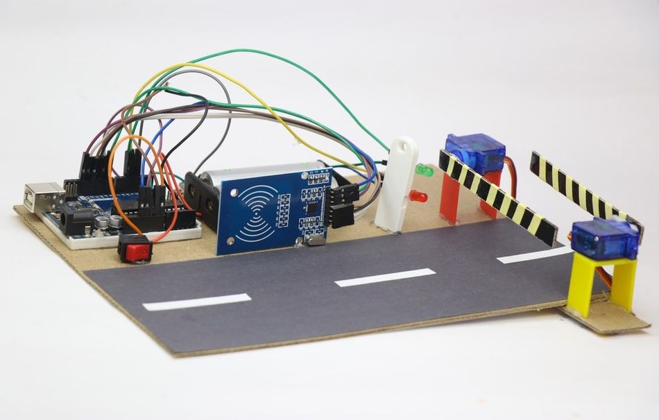
To illustrate how the pinout enables real‑world Arduino projects, this section presents two practical examples: controlling a servo motor using PWM and interfacing an ultrasonic distance sensor using digital I/O and timing functions. [4]
Servo Motor Control
Servo motors require a control pulse between 1 ms and 2 ms at about 50 Hz. The Arduino Servo library uses Timer1 to generate these pulses. Connect the signal wire of the servo to pin 9 or 10 (Timer1 PWM pins) and the power source from an external 5 V source capable of delivering the servo’s stall current.
The code below works for this specific application:
#include <Servo.h>

Servo myServo;

void setup()
{
  myServo.attach(9); // attach servo to pin 9
}

void loop()
{
  for (int angle = 0; angle <= 180; angle += 5)
  {
    myServo.write(angle);
    delay(50);
  }
  for (int angle = 180; angle >= 0; angle -= 5)
  {
    myServo.write(angle);
    delay(50);
  }
}
This sketch sweeps the servo arm between 0° and 180°. This makes Arduino Uno a popular microcontroller for robotics, especially for controlling servo motors, which provide precise angular movement for robotic arms, pan-tilt mechanisms, and other mobile robots, using PWM signals.
Ultrasonic Distance Measurement
Ultrasonic sensors like the HC‑SR04 provide distance measurements by transmitting a pulse and measuring the echo time. Connect the trigger pin to a digital output and the echo pin to a digital input capable of timing pulses (any pin with pulseIn() can be used).
The example below measures distance in centimetres.
const int trigPin = 7;
const int echoPin = 6;

void setup()
{
  Serial.begin(9600);
  pinMode(trigPin, OUTPUT);
  pinMode(echoPin, INPUT);
}

void loop()
{
  digitalWrite(trigPin, LOW);
  delayMicroseconds(2);
  digitalWrite(trigPin, HIGH);
  delayMicroseconds(10);
  digitalWrite(trigPin, LOW);
  long duration = pulseIn(echoPin, HIGH);
  float distance = (duration / 2.0) * 0.0343; // sound speed ≈ 343 m/s
  Serial.print("Distance: ");
  Serial.print(distance);
  Serial.println(" cm");
  delay(200);
}
This example demonstrates precise control of pulse timing and highlights the importance of using the correct digital pins for time‑critical measurements.
Recommended Reading: Arduino vs Raspberry Pi: Choosing the Right Platform for Your Next Project
Conclusion
The Arduino UNO pinout provides a rich interface to the ATmega328P microcontroller, exposing a combination of digital, analog, power and communication pins. Understanding the capabilities and limitations of each pin allows digital design and hardware engineers to build reliable systems. The UNO offers 14 digital pins, 6 analog inputs, PWM outputs, UART, SPI and I²C interfaces, power regulation and a standard shield footprint. Respecting electrical limits and practicing good design principles — such as proper decoupling, current limiting and level shifting ensures longevity and reliability.
For students, the UNO serves as a practical platform to learn microcontroller programming, digital logic, analog measurement and communication protocols. For professionals, it provides a quick way to prototype circuits and test algorithms before migrating to a custom PCB. Keep tutorials, datasheets, schematics, and this pinout guide readily available once you explore the Arduino ecosystem. This will streamline your prototyping, help avoid mistakes and discover new potential.
Frequently Asked Questions (FAQs)
1. How many pins does the Arduino UNO have?
A. The Arduino UNO R3 has 14 digital I/O pins (labeled D0 to D13) and 6 analog input pins (labeled A0 to A5). Including power and control pins, the header exposes a total of 20 General Purpose Input/Output (GPIO) lines.
2. Can the analog pins be used as digital pins?
A. Yes. The pins A0–A5 correspond to digital pins, and these can be used when configured using pinMode(), and controlling them with digitalRead() or digitalWrite(). However, avoid using A4 and A5 as general digital pins if your application uses I²C on the same bus.
3. What is the maximum current a digital pin can supply?
A. Each I/O pin can source or sink up to 40 mA, but the recommended continuous limit is 20 mA, and the total across all pins should not exceed 200 mA.
4. Which pins support PWM on the UNO?
A. The digital pins 3, 5, 6, 9, 10 and 11 support PWM. The timers generate PWM, and the default frequency is about 490 Hz or 980 Hz, depending on the timer.
5. What is the purpose of the ICSP header?
A. The ICSP header exposes the SPI pins, reset, power and ground for in‑circuit programming. You can use it to program the bootloader or to flash firmware directly onto the ATmega328 P.
6. Can I use the UNO with 3.3 V sensors?
A. Yes, but you must protect the sensors from 5V logic. It is better to use level shifters or resistor dividers on the outputs of UNO and ensure the output lines of the sensors are 5V tolerant. Alternatively, power the UNO from 3.3V using a variant, like the Arduino Pro Mini (3.3V version) or use a dedicated 3.3V board.
References
[1] Arduino. Official Arduino UNO Documentation [Cited 2025 December 24]. Available at: Link
[2] Microchip Technology. ATmega328P Microcontroller [Cited 2025 December 24]. Available at: Link
[3] Arduino. Digital Pins | Arduino Documentation [Cited 2025 December 24]. Available at: Link
[4] NTU Singapore. Getting Started with Arduino [Cited 2025 December 24]. Available at: Link
in this article
1. Key Takeaways2. Introduction3. Overview of the Arduino UNO Board4. Power Supply Pins and Voltage References5. Digital I/O Pins (0–13)6. PWM and Analog Output Emulation7. Analog Input Pins (A0–A5)8. Communication Interfaces9. Interrupts and Timers10. Practical Design Considerations11. Example Applications12. Conclusion13. Frequently Asked Questions (FAQs)14. References