Flying Probe Test: An Extensive Guide to the Technology and Applications
A Comprehensive Introduction to Flying Probe Test, its Essential Components, Advantages, Limitations, and Application Cases

28 Sep, 2023. 16 minutes read
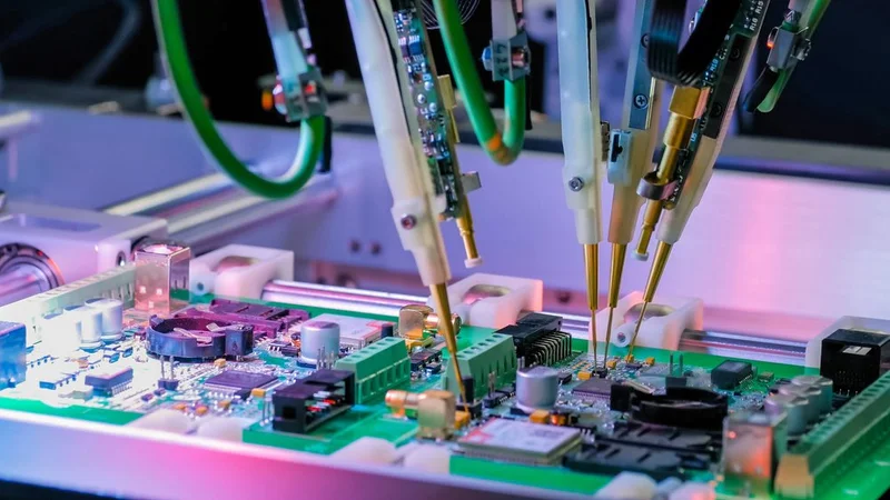
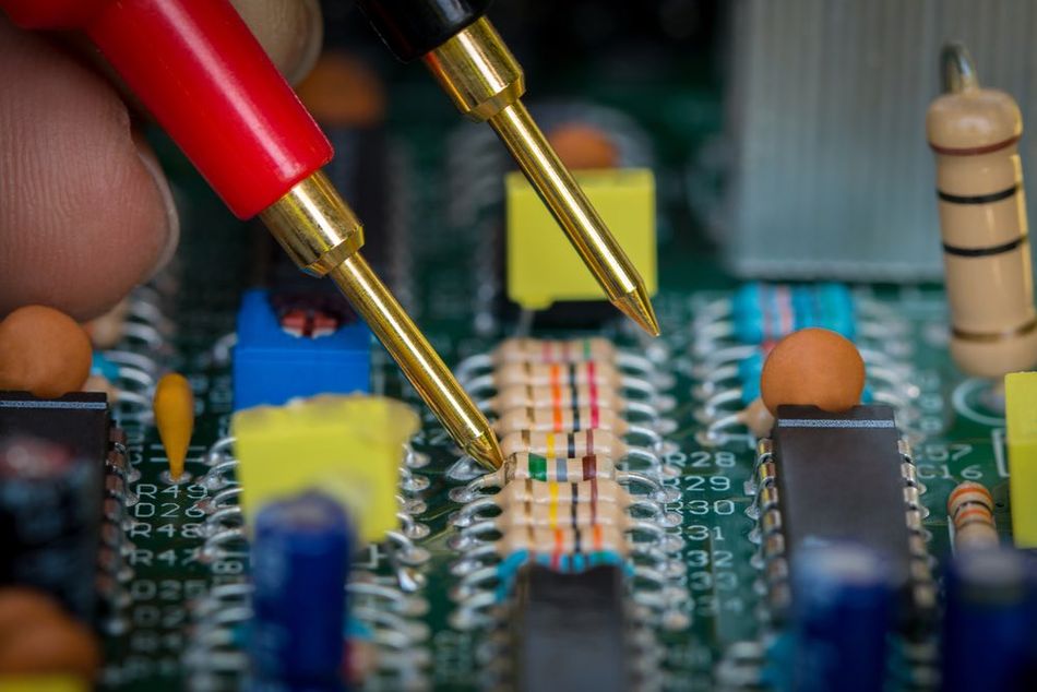
Flying Probe Test at a Factory
Introduction
Flying probe tests are a critical aspect of the electronics industry, ensuring the quality and functionality of electronic components and systems. These tests utilize specialized equipment to perform various contact and non-contact electrical tests on printed circuit boards (PCBs), printed wiring boards (PWBs), PCB assembly (PCBA), individual components, and entire systems. By providing a flexible and efficient method for identifying defects and verifying performance, flying probe tests have become an essential tool for manufacturers and engineers.
This article will help circuit designers and testers:
Understand the fundamentals of flying probe tests
Explore the critical components of flying probe test systems
Understand the advantages and limitations of flying probe tests.
Understand various applications of FPT in the electronics industry.
What is a Flying Probe Test?
A flying probe test is a testing method for electronic circuits primarily used to test PCBs. It employs a system of movable probes that virtually "fly" over the circuit board, making electrical contact with specific test points on the PCB.
Ultimately, it identifies defects and verifies the electrical performance of the circuit. The flying probe test system consists of several key components, including the probes themselves, a test fixture to hold the PCB in place, and control software to manage the testing process.
The Outcome of a Flying Probe Test
Primarily, a flying probe test serves two critical purposes, i.e.,
Defect Identification - Picking manufacturing defects like short circuits, open circuits, and misalignments. Moreover, it also detects the location of the defect.
Performance Verification - Verifying the electrical performance of the PCB to ensure that it serves the purpose of production.
This testing method is particularly beneficial for small production runs and prototype development, as it does not require the creation of a dedicated test fixture for each PCB design. Instead, the flying probe test system can be quickly reconfigured to accommodate different PCB layouts, making it a highly flexible and cost-effective solution for electronics manufacturers.
One of the critical features of a flying probe test system is its ability to perform both in-circuit tests (ICT) and functional tests (FCT). In-circuit tests involve checking the PCB connectivity and functionality while functional tests verify the overall performance of the assembled board.
By combining these two testing approaches, flying probe test systems can provide a comprehensive assessment and valuable insights at various stages of a PCB design process to ensure the quality and reliability of specifications and performance standards.
Types of Flying Probe Test Systems
Several flying probe tester systems are designed to cater to specific testing requirements and applications. The main types of flying probe test systems include
Single-sided Systems
These systems are equipped with probes that can access only one side of the PCB at a time. Single-sided systems are typically used for testing simpler PCB and PWB designs with fewer layers and test points.
They offer a more cost-effective solution for manufacturers with less complex and low-volume testing needs. These systems can also be ideal for single-sided PWBs to check for solder connectivity, continuity, shorts, open circuits, and wiring-related electrical issues.
However, they may not be suitable for testing densely populated or multi-layered PCBs, as they cannot simultaneously access test points on both sides of the board.
Recommended Reading: PWB vs PCB: Differences and Similarities
Double-sided Systems
In double-sided flying probe test systems, the probes can simultaneously access both sides of the PCB or circuit board assembly. This allows for more efficient testing of complex, multi-layered PCBs with test points on both sides of the board.
Double-sided systems are generally faster and more accurate than single-sided systems, as they can perform in-circuit and functional board testing on both sides of the PCB without manual intervention or repositioning.
However, they tend to be more expensive and require a larger footprint, making them more suitable for larger-scale production environments.
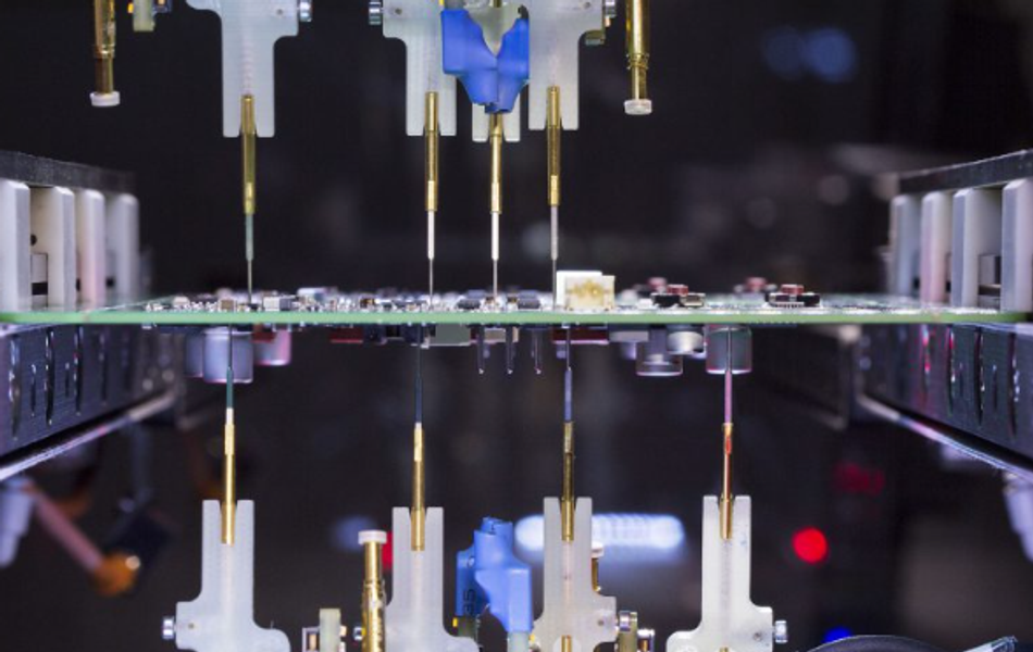
Image Source: Flying Probe Test for electronic boards PCB - Automatic Flying Probe Testers | SPEA
Vertical Systems
Vertical flying probe test systems are designed vertically, allowing the PCB to be tested upright. This configuration can save valuable floor space in production facilities and is particularly advantageous for testing large or heavy PCBs that may be difficult to handle in a horizontal orientation. Vertical systems can be single-sided or double-sided, depending on the testing requirements.
High-speed Systems
High-speed flying probe test systems are designed to perform tests faster than traditional systems, reducing the overall testing time and increasing production throughput. These systems often feature advanced motion control technology, high-precision probes, and optimized control software to achieve faster test speeds without sacrificing accuracy or reliability. High-speed systems benefit manufacturers with high-volume production requirements or tight production schedules.
Essential Components of Flying Probe Test Systems
A flying probe tester consists of three major components, i.e.
Probes
Test Fixtures
Control Software
The three components work in conjunction to ensure fast and accurate testing for PCBs.
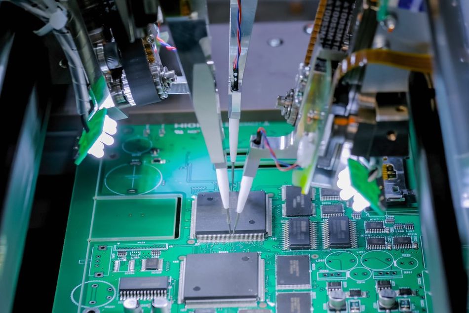
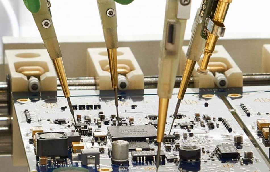
Image Source: https://www.note-uk.co.uk/uk-manufacturing/flying-probe-test/
Probes
Probes are the primary contact points between the flying probe test system and the PCB being tested. They transmit electrical signals to and from the PCB, allowing the test system to measure and analyze the circuit's performance. These probes are mounted on a platform that can move in x,y, and z directions to access test points and vias for different PCB tests.
Several types of probes are used in flying probe test systems, each with specific characteristics and applications.
Spring-loaded Probes - Also known as pogo pins, spring-loaded probes are the most common type used in flying probe test systems because they are cost-effective and reliable. They consist of a plunger, barrel, and spring, which allows the probe to maintain consistent contact pressure with the PCB test points.
Active Probes - These probes feature built-in electronic components like amplifiers and signal conditioning circuits. It enables them to perform more advanced testing functions, making them useful for
High-frequency or high-precision measurements
Testing sensitive components that may be susceptible to damage from traditional probe contact.
Generally, active probes are more expensive than spring-loaded probes and may require additional calibration or maintenance.
Kelvin Probes - These are also known as four-wire probes. They are designed to perform highly accurate low-resistance measurements on current sense resistors. They have a four-wire configuration, with two wires connected to the current source and two to the voltage measurement device. This arrangement allows the probe to eliminate the effects of contact and lead resistance, resulting in more accurate and repeatable measurements.
High-voltage Probes - These probes are specially designed to materials and insulation to withstand and measure high voltage levels, typically above 1,000 volts without causing damage to the PCB.. High-voltage probes are used to test applications involving high-voltage components, like power supplies and high-voltage transformers.
Test Fixture
The test fixture is responsible for holding the PCB securely in place during the testing process. A well-designed test fixture can smoothen the testing process by
Ensuring accurate and consistent probe contact with the PCB test points
Minimizing the risk of false readings or damage to the board.
Several types of test fixtures are used in flying probe test systems, each with specific advantages and applications.
Mechanical Fixtures - These are the most common type of fixture used in flying probe test systems, typically consisting of a rigid frame, adjustable clamps, and support pins holding the PCB during testing. They often require manual adjustment and customization but are relatively simple and cost-effective, making them suitable for various testing applications.
Vacuum Fixtures - These fixtures use suction to hold the PCB securely against a flat surface during testing. This fixture provides uniform support across the entire PCB, minimizing the risk of board flexing or damage during probe contact. Vacuum fixtures are handy for testing thin or flexible PCBs and high-speed or high-precision testing applications. However, they may be more expensive and require additional maintenance compared to mechanical fixtures.
Pneumatic Fixtures - These fixtures use compressed air to apply pressure and hold the PCB in place during testing. These fixtures offer a high degree of automation and repeatability, making them suitable for high-volume production environments. Pneumatic fixtures can be easily adjusted to accommodate different PCB designs and provide consistent clamping force across the board. However, they may be more complex and costly than mechanical or vacuum fixtures and require additional infrastructure, such as compressed air supply and control systems.
Control Software
Control software manages the testing process to ensure accurate and efficient test execution. The software coordinates the movement of the probes, controls the test fixture, and processes the test data to generate meaningful results. There are several key features and functions of control software in flying probe test systems:
Test Program Generation - The control software creates the test program, which defines the sequence of test steps, probe movements, and measurements to be performed on the PCB. It typically involves importing the PCB design data, such as Gerber files or CAD data, and automatically generating a test program based on the test points and components specified in the design. The software may also provide tools for manual editing and optimization of the test program to improve test efficiency and accuracy.
Probe Path Optimization - Control software features algorithms for optimizing the probe movement paths. It helps minimize the testing time as the algorithms calculate the most efficient sequence of probe movements to reduce travel distance. It’s essential for high-volume production environments, where even minor improvements in test speed can result in significant cost savings.
Data Analysis and Reporting - The control software also processes the test data collected by the probes and generates detailed reports on the PCB's performance and any detected defects. These reports include pass/fail results, measurement data, graphical test points and component representations. The software may also provide:
Tools for analyzing the test data.
Identifying trends or patterns.
Generating statistical process control (SPC) charts to monitor the production process's quality and stability.
Integration with Other Systems -In many production environments, flying probe test systems must be integrated with other manufacturing equipment, such as automated optical inspection (AOI) systems, X-ray inspection systems, or pick-and-place machines. Control software may include features for seamless integration with these systems, allowing for streamlined data exchange and coordination between different stages of the production process.
Process Flow for a Flying Probe Test
Flying Probe Testing involves multiple hardware and software setup processes. Here is the process flow for a typical FPT process.
Creating a Test Program
Initiation of the flying probe testing process begins with creating a test program. This program encompasses directives for the probes to assess the board, specifying the test types, voltage parameters, and the precise locations of the test points.
Positioning the Probe
With the test program in place, the test probes are maneuvered into position. These probes are affixed to a platform that permits movement along the X, Y, and Z axes, ensuring accurate placement over the designated test points on the board.
Program Execution
Upon achieving proper positioning, the test program is executed. The probes establish contact with the board's test points and apply the predetermined voltage levels. The program subsequently measures essential electrical characteristics of the test points, such as current, resistance, capacitance, and inductance.
Result Evaluation
Following completion of the test, the outcomes are scrutinized to ascertain the board's functionality. Corrective action, such as reworking or replacement, may be necessary if any anomalies or defects are detected.
Advantages of Flying Probe Test Systems
Flying Probe Test offers various advantages over some of the other methods of PCB testing. Here are some of its key advantages.
Flexibility
Flying probe test systems are flexible and can be reconfigured according to different board layouts, offering more versatility than bed-of-nails testers. It makes them an ideal solution for small production runs, prototype development, and frequent design changes, as they can quickly adapt to new testing requirements without needing costly and time-consuming fixture modifications.
Reduced Setup Time and Cost
Since flying probe test systems do not require dedicated test fixtures for each PCB design, they can significantly reduce setup time and cost. The PCB manufacturing process as the control software can automatically generate test programs based on the PCB design data, allowing for rapid deployment of new tests without manual programming or fixture fabrication, saving cost, especially for manufacturers with diverse product portfolios or frequent design changes.
High Test Coverage and Accuracy:
Flying probe test systems can achieve high test coverage and accuracy by combining in-circuit and functional tests in a single testing process. The movable probes can access a wide range of test points on the PCB, including those that may be difficult or impossible to reach with traditional test methods. This enables the detection of a broad range of defects, such as open circuits, short circuits, and component misalignments, as well as the verification of the PCB's electrical performance.
Nondestructive Testing
Flying probe test systems perform non-contact testing, which minimizes the PCB damage risk during the testing process. The probes make gentle contact with the test points, reducing the likelihood of damage caused by excessive pressure or mechanical stress. This is particularly beneficial for testing delicate or sensitive components susceptible to damage from traditional contact-based testing methods.
Scalability
Flying probe test systems can be easily scaled to accommodate varying production volumes and testing requirements. Additional probes or test modules can be added to the system to increase testing capacity, while the control software can be updated to support new testing features or capabilities. This scalability allows manufacturers to adapt their testing processes to meet changing market demands and production goals, ensuring they can maintain high levels of quality and reliability across their product lines.
Limitations of Flying Probe Test Systems
Reduced Testing Speed
One of the main limitations of flying probe test systems is their testing speed. Since the probes must physically move to each test point on the PCB, the testing process can be slower than traditional bed-of-nails testers or automated optical inspection (AOI) systems. This can concern manufacturers with high-volume production requirements or tight production schedules, as the slower testing speed may impact overall throughput and efficiency.
Complex Test Setup
While flying probe test systems offer flexibility and reduced setup costs compared to dedicated test fixtures, their setup and configuration can be complex. Generating test programs, optimizing probe paths, and integrating the test system with other manufacturing equipment require specialized knowledge and expertise. This may challenge manufacturers with limited resources or experience in flying probe testing.
Limited Test Point Access
Although flying probe test systems can access a wide range of test points on a PCB, some test points may be unreachable due to component density, board layout, or physical constraints. In such cases, alternative testing methods, such as AOI or X-ray inspection, may be required to achieve complete test coverage.
Potential for False Readings
Flying probe test systems rely on precise probe contact with the PCB test points to obtain accurate measurements. However, probe wear, contamination, or misalignment can result in false readings or inconsistent test results. Regular maintenance, calibration, and probe replacement may be necessary to ensure the reliability and accuracy of the test system.
Cost and Footprint
While flying probe test systems can offer cost savings compared to traditional test fixtures, they can still be expensive to purchase and maintain, particularly for high-speed or double-sided systems. Additionally, the test equipment can require a significant amount of floor space, which may concern manufacturers with limited production facilities or those looking to optimize their production layout.
Applications of Flying Probe Test Systems
FPT has several application cases thanks to its flexibility and ease of testing. Here are some major applications for FPT.PCB, PWB, and PCBA Testing
Flying probe test systems are widely used for testing printed circuit boards (PCBs) in the electronics industry. Their flexibility and adaptability make them an ideal solution for various PCB testing scenarios, from prototype development to small and medium production runs.
During PCB testing, flying probe test systems perform both in-circuit tests (ICT) and functional tests (FCT) to ensure the quality and reliability of the assembled boards.
In-Circuit Testing
In-circuit tests involve checking the connectivity and functionality of individual components on the PCB, such as resistors, capacitors, and integrated circuits. This helps identify manufacturing defects, such as short circuits, open circuits, and component misalignments, which can impact the final product's performance.
Functional Testing
Functional tests verify the overall performance of the assembled PCB by simulating its operation under real-world conditions. This can include testing the power supply, signal integrity, and communication interfaces and verifying the correct operation of embedded software or firmware.
One of the key advantages of using flying probe test systems for PCB testing is their ability to accommodate a wide range of board designs and test requirements without requiring dedicated test fixtures. This makes them particularly suitable for manufacturers with diverse product portfolios or those who frequently update their PCB designs.
Additionally, the non-contact testing method employed by flying probe test systems minimizes the risk of damage to the PCB or its components during the testing process, ensuring the integrity of the final product.
Recommended Reading: PCB Testing: A Comprehensive Guide to Techniques, Tools, and Best Practices
Component-Level Testing
Component-level testing focuses on verifying the performance and functionality of individual electronic components, such as resistors, capacitors, inductors, and integrated circuits, before they are assembled onto a PCB.
By identifying faulty or out-of-spec components early in the production process, manufacturers can reduce the risk of assembling defective PCBs and improve their products' overall quality and reliability.
Flying probe test systems can perform a variety of component-level tests, including:
Passive Component Testing - Testing capacitors, resistors, and inductors by measuring their corresponding physical parameters.
Active Component Testing - Testing active components, such as transistors, diodes, and integrated circuits, by performing advanced tests to verify their functionality and performance characteristics.
Optoelectronic Component Testing - Tests for optoelectronic components like LEDs, photodiodes, and optocouplers. These tests can involve measuring parameters like forward voltage, luminous intensity, and spectral characteristics.
Recommended Reading: Components of a PCB: A Comprehensive Guide
System-Level Testing
System-level testing evaluates the performance and functionality of complete electronic systems or sub-assemblies. This type of testing is essential for ensuring that the assembled product meets the required specifications and operates correctly under real-world conditions. It encompasses various tests, from power supply testing to communication interface verification and embedded software validation.
Flying probe test systems can be employed in various system-level testing scenarios, including:
Power Supply Testing - Measuring input and output voltages, current consumption and efficiency in power supplies.
Signal Integrity Testing - Evaluating signal integrity of high-speed communication interfaces and data buses, and checking falling times, jitter, and eye diagrams to identify possible factors affecting signal integrity.
Embedded Software and Firmware Testing
For electronic systems with embedded software or firmware, flying probe test systems can perform functional tests to ensure the correct operation of the software under different conditions. This can involve executing test scripts, simulating user inputs, and monitoring system outputs to verify that the software behaves as expected and meets the specified performance criteria.
Environmental and Stress Testing
Flying probe test systems can also be used with environmental chambers or stress testing equipment to evaluate the performance and reliability of electronic systems under various environmental conditions, such as temperature, humidity, and vibration. For instance, it involves Thermal Cycling, Highly Accelerated Life Testing (HALT), temperature-humidity testing, etc. This can help identify potential failure modes and ensure the system meets the required durability and reliability standards.
Best Practices for Flying Probe Test Systems
Regular Maintenance and Calibration
To ensure the accuracy and reliability of flying probe test systems, it is essential to perform regular maintenance and calibration. This includes cleaning and inspecting the probes, test fixture, and other system components and calibrating the probe movement and measurement systems. Regular maintenance and calibration can prevent false readings, improve test repeatability, and extend the life of the test equipment.

Optimizing Test Programs and Probe Paths
To maximize testing efficiency and minimize test time, it is important to optimize the test programs and probe paths used by the flying probe test system. This can involve using the control software's built-in optimization algorithms, as well as manually reviewing and adjusting the test program to eliminate redundant or unnecessary test steps. Moreover, since FPT relies on cameras for optimized operations, it also paves the way for advanced scanning techniques for PCB inspection.
Proper Fixture Design and PCB Support
Ensuring proper fixture design and PCB support is crucial for accurate and consistent probe contact during testing. This includes selecting the appropriate test fixture type, such as mechanical, vacuum, or pneumatic fixtures, and ensuring that the PCB is securely held in place with minimal flexing or movement during testing. Since it ensures PCB support, it can help prevent false readings and improve the overall test accuracy.
Integration with Other Manufacturing Processes
To streamline the production process and improve overall efficiency, it is important to integrate the flying probe test system with other manufacturing equipment, such as AOI systems, X-ray inspection systems, or pick-and-place machines. This can involve coordinating data exchange between the different systems, synchronizing test schedules, and automating the transfer of PCBs between different stages of the production process.
Continuous Monitoring and Improvement:
Finally, it is essential to continuously monitor the performance of the flying probe test system and implement improvements as needed. This can involve analyzing test data, identifying trends or patterns, and generating statistical process control (SPC) charts to monitor the quality and stability of the production process. By actively monitoring and improving the test system's performance, manufacturers can ensure high quality and reliability levels across their product lines.
Conclusion
Flying probe test systems play a crucial role in the electronics industry, offering a flexible and efficient method for testing PCBs, components, and entire systems. By understanding the fundamentals, key components, advantages, and limitations of flying probe test systems, manufacturers can make informed decisions when selecting the most suitable testing solution for their specific needs. Moreover, by following best practices and continuously monitoring and improving the test system's performance, manufacturers can ensure high levels of quality and reliability across their product lines.
Frequently Asked Questions (FAQs)
1. What is a flying probe test?
A flying probe test is a non-contact method of testing electronic circuits, primarily used for testing printed circuit boards (PCBs). It employs a system of movable probes that make contact with specific test points on the PCB, allowing for the detection of defects and verification of electrical performance.
2. What are the main types of flying probe test systems?
The main types of flying probe test systems include single-sided systems, double-sided systems, vertical systems, and high-speed systems. Each type has its unique advantages and limitations, making it essential for manufacturers to carefully consider their specific testing needs and production requirements when selecting the most suitable system.
3. What are the key components of a flying probe test system?
The key components of a flying probe test system include probes, a test fixture, and control software. The probes make contact with the PCB test points, the test fixture holds the PCB in place during testing, and the control software manages the testing process.
4. What are the advantages of flying probe test systems?
Some advantages of flying probe test systems include flexibility, reduced setup time and cost, high test coverage and accuracy, non-destructive testing, and scalability.
5. What are the limitations of flying probe test systems?
Some limitations of flying probe test systems include testing speed, complexity of test setup, limited access to test points, potential for false readings, and cost and footprint.
References
Next PCB. “What is PCB Testing”
Andrea Calabrese, Stefano Quer, Giovanni Squillero, (2021). “Smart Techniques for Flying-probe Testing”, https://www.scitepress.org/Papers/2021/105823/105823.pdf
Candor Circuit Boards, (2021). “Flying Probes & Testing: Everything You Need to Know”
Reverse PCB, (2021). “How to Conduct a Flying Probe Test (FPT)?”
Advanced Assembly. “7 Types of PCB Testing Methods: What You Need To Know”
Millenium Circuits Limited. “Printed Circuit Board Testing Methods Guide”
JHD PCB. “The Ultimate Guide To Flying Probe Testing (FPT) Of PCBs”
in this article
1. Introduction2. What is a Flying Probe Test?3. The Outcome of a Flying Probe Test4. Types of Flying Probe Test Systems5. Essential Components of Flying Probe Test Systems6. Process Flow for a Flying Probe Test7. Advantages of Flying Probe Test Systems8. Limitations of Flying Probe Test Systems9. Applications of Flying Probe Test Systems10. Best Practices for Flying Probe Test Systems11. Conclusion12. Frequently Asked Questions (FAQs)13. References