Understanding Circuit Board Components: A Comprehensive Guide
This guide provides an in-depth understanding of circuit board components, highlighting their basics, types, design process, and troubleshooting for various applications.

19 Jan, 2024. 18 minutes read
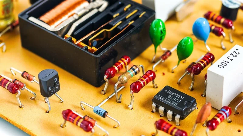
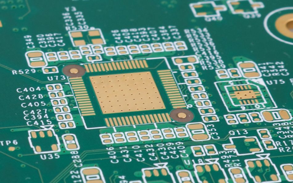
Circuit board components or SMDs etched on an electronic board
Introduction to Circuit Board Components
Electronic devices are built on a foundation of circuit board components. These components are the essential building blocks of everything from simple electronic toys to complex supercomputers. Circuit board components come in a variety of types, including resistors, capacitors, inductors, transistors, and diodes. Each component has its unique function, and together they work to create the complex electronic systems that we rely on every day. The complexity and variety of these components can be overwhelming. However, with a solid understanding of their basic principles and functions, one can begin to understand and appreciate the intricate world of electronics.
The Basics of Circuit Boards
A circuit board, also known as a printed circuit board (PCB), is a thin plate on which chips and other electronic components are placed. Computers, radios, televisions, and other electronic devices contain one or more circuit boards. A PCB is made of insulating material or substrate often fibreglass, with conductive material pathways etched or "printed" onto its surface. [1] These pathways connect the components and allow electrical current to flow between them.
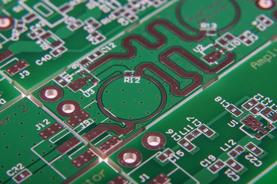
The basic function of a circuit board is to provide a conductive pathway to electrical components. This is achieved through the use of copper traces that direct the flow of electricity. The complexity of the circuit, the number of components and the required space will determine the number of copper layers within a PCB.
The components on a circuit board are typically soldered to the board and are therefore firmly attached. The location of the components and the paths for electricity are determined by the design of the circuit board. This design is usually created by computer software which allows for precise control over where components are placed and where tracks are laid.
Recommended Reading: What are Circuit Boards Made Of? An Extensive Guide to Materials and PCB Manufacturing Processes
Types of Circuit Boards
The invention of the PCB has made electronic devices smaller, more efficient, and easier to produce. The compact design allows for a large number of components to be included in a small space, leading to complex and powerful devices.
There are several types of circuit boards, each with its specific applications and advantages.
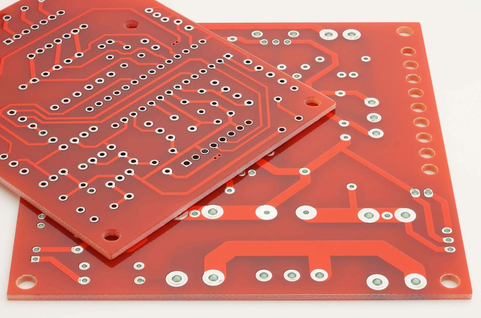
Single-sided PCBs are the simplest type of circuit board, with components and copper tracks on one side of the board only. They are used in simple electronic devices such as calculators and radios.
Double-sided PCBs have components and tracks on both sides of the board. This allows for more complex circuits, as tracks can cross over each other using 'vias' - small holes filled with conductive material that allow electricity to pass from one side of the board to the other. [2] Double-sided PCBs are used in more complex devices such as smartphones and laptops.
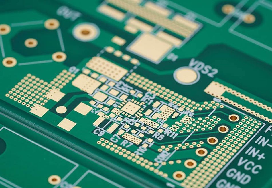
Multilayer PCBs have multiple layers of copper tracks separated by insulating material. This allows for extremely complex circuits to be created in a relatively small space. Multilayer PCBs are used in high-performance devices such as servers and advanced medical equipment.
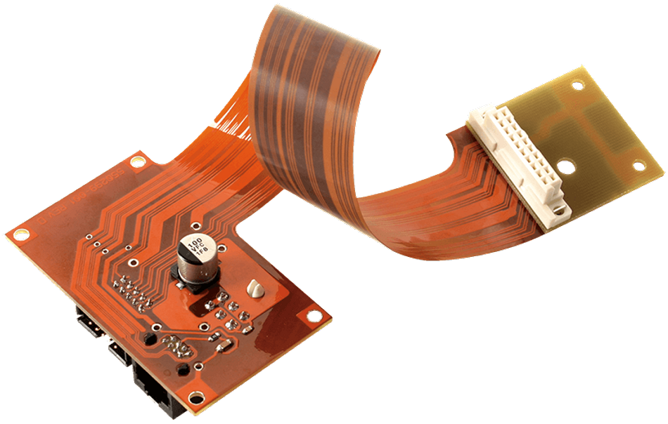
Flexible PCBs are made from flexible materials, allowing them to be bent and folded. This makes them ideal for use in devices where space is at a premium, or where the circuit board needs to fit into a specific shape. Flexible PCBs are often used in cameras, car dashboards, and other compact electronic devices.
Each type of circuit board has its specific uses and advantages, and the choice of which type to use will depend on the requirements of the electronic device in question. Understanding these different types of circuit boards is a key part of understanding circuit board components.
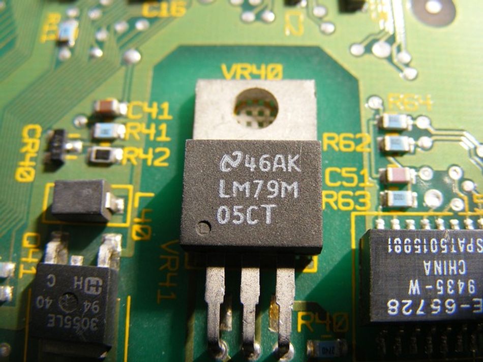
Understanding Circuit Board Components
Circuit board components are the individual elements that make up the circuit on a PCB. These components are typically soldered onto the PCB and are interconnected by the copper tracks to form the circuit. The components used, and their configuration on the PCB, will depend on the specific function of the circuit.
Each component on a circuit board has a specific function. Some components, such as resistors, capacitors, and inductors, are used to control the flow of electricity around the circuit. Others, such as diodes and transistors, are used to control the direction of that flow, or to amplify the electrical signal.
The components on a circuit board are typically divided into two categories: active and passive. Active components, such as transistors and integrated circuits (ICs), can amplify or switch electronic signals, while passive components, such as resistors, capacitors, and inductors, cannot.
The choice of components, and their arrangement on the PCB, will depend on the specific requirements of the circuit. For example, a simple flashlight circuit may only require a battery, a switch, and a light bulb. On the other hand, a more complex device such as a computer will require a wide range of components in a variety of configurations.
Resistors
Resistors are a type of passive component that are used to limit the flow of electricity in a circuit. They are one of the most common components found on a circuit board, and are used in almost all electronic devices. Resistors are the basic building blocks of rectifiers, relays, fuses, and microcontrollers.

A resistor's main function is to provide a specific amount of resistance to the flow of electrical current. This resistance is measured in ohms (Ω). The amount of resistance a resistor provides determines how much current will flow through it for a given voltage, according to Ohm's Law:

where V is voltage, I is current, and R is resistance.
Resistors come in many different types, each with its specific characteristics and uses. Some common types of resistors include:
Fixed resistors offer a consistent and predetermined resistance value. They can be further categorized into Carbon Composition Resistors, Metal Film Resistors, Metal Oxide Resistors, and Wirewound Resistors.
Variable resistors allow you to adjust their resistance value manually or electronically. They come in various forms, including Potentiometers, Rheostats, and Trimpots.
Special resistors offer unique properties or functionalities beyond simply controlling resistance. Some examples include Thermistors, Photoresistors, and Varistors.
The resistance value of a resistor is typically indicated by a series of colored bands on the resistor's body. Each color corresponds to a specific number, and the sequence of colors indicates the resistor's resistance value in ohms. [3]
Resistors are used in a wide range of applications on a circuit board. For example, they can be used to control the brightness of a light, the volume of a speaker, or the speed of a motor. They can also be used in combination with capacitors to create amplifiers and filters that can separate different frequencies of an electrical signal.
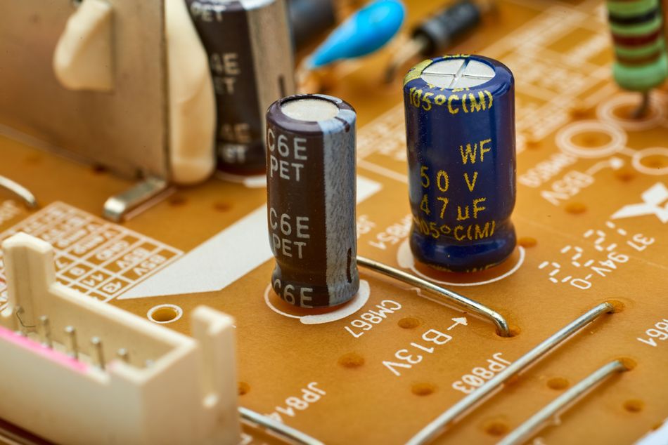
Capacitors
Capacitors are another type of passive component found on circuit boards. They store electrical energy in an electric field and can release it when needed. Capacitors play a crucial role in many electronic circuits, such as filtering, energy storage, and coupling or decoupling signals.
A capacitor consists of two conductive plates separated by an insulating material called a dielectric. When a voltage is applied across the capacitor, an electric field forms between the plates, causing positive and negative charges to accumulate on the plates. The amount of electric charge a capacitor can store is determined by its capacitance, which is measured in farads (F). The formula to calculate capacitance is:

where Q is charge stored, V is voltage, and C is capacitance.
Capacitors come in various types, each with its own specific characteristics and applications. Some common types of capacitors include:
Ceramic capacitors are made from ceramic materials and are often used for high-frequency applications due to their low parasitic inductance and resistance. They are typically small in size and have capacitance values ranging from picofarads (pF) to microfarads (µF).
Electrolytic capacitors have a larger capacitance value compared to ceramic capacitors, typically ranging from microfarads (µF) to millifarads (mF). They are often used for energy storage and filtering in power supply circuits. Electrolytic capacitors are polarized, meaning they have a positive and negative terminal and must be connected correctly in a circuit.
Film capacitors are made from thin plastic films and are known for their stability, low distortion, and wide temperature range. They are often used in audio and radio frequency circuits.
Tantalum capacitors are similar to electrolytic capacitors but use tantalum as the anode material. They offer high capacitance values in a small package and are often used in space-constrained applications.
Capacitors have various applications in electronic circuits. Some common uses include:
Filtering: Capacitors can be used to filter out unwanted frequencies in a signal. For example, they can be used in combination with resistors to create low-pass, high-pass, or band-pass filters.
Energy storage: Capacitors can store energy and release it when needed, making them useful in power supply circuits and energy-harvesting applications.
Coupling and decoupling: Capacitors can be used to couple or decouple signals between different stages of a circuit. For example, they can be used to block direct current (DC) while allowing alternating current (AC) to pass through.
Timing: Capacitors can be used in combination with resistors to create timing circuits, such as those used in oscillators and timers.
Understanding the different types of capacitors, their specifications, and their applications is essential for anyone working with PCB components.
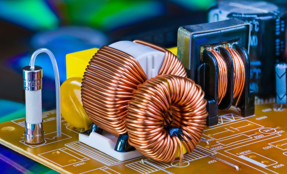
Inductors
Inductors are another type of passive component found on circuit boards. They are used to store energy in a magnetic field when electric current passes through them. Inductors are often used in electric circuits where the control of current over time is crucial, such as in filters, oscillators, and transformers.
An inductor is typically made from a coil of wire wound around a magnetic or non-magnetic core. The amount of inductance, which is the ability of the inductor to store energy, is determined by factors such as the number of turns in the coil, the coil's radius, and the type of material used for the core. Inductance is measured in henries (H). The formula to calculate inductance is:

where L is inductance, u is permeability, N is number of turns in coil, A is area encircled by coil, and l is length of coil.
When current flows through the coil, it creates a magnetic field around the inductor. If the current changes, the changing magnetic field induces a voltage in the coil that opposes the change in current. This property, known as self-induction, is the basis for many of the applications of inductors in electronic circuits. [4]
Inductors come in various types, each with its own specific characteristics and applications. Some common types of inductors include:
Air-core inductors have no core other than air. These inductors have low inductance and are often used in high-frequency applications where low inductance values are required.
Ferrite-core inductors use a core made from ferrite, a type of ceramic material that is magnetic. Ferrite-core inductors have higher inductance values than air-core inductors and are used in a wide range of applications, including power supplies and radio frequency circuits.
Iron-core inductors use a core made from iron or an iron alloy. These inductors have high inductance values and are often used in power applications.
Toroidal inductors have a core in the shape of a torus (a doughnut shape). The coil is wound around the entire surface of the core, which helps to contain the magnetic field within the core and reduce electromagnetic interference.
Inductors have various applications in electronic circuits. Some common uses include:
Filtering: Inductors can be used in combination with capacitors to create filters that can separate different frequencies of an electrical signal.
Energy storage: Inductors can store energy in their magnetic field and release it when needed, similar to capacitors.
Oscillators: Inductors can be used in combination with capacitors to create oscillators, which generate a periodic signal.
Transformers: Inductors can be used in transformers, where two or more inductors are coupled together to transfer energy from one circuit to another.
Understanding the different types of inductors, their specifications, and their applications is essential for anyone working with circuit board components.
Diodes
Diodes are a type of semiconductor device that allow current to flow in one direction but not the other. They are an essential component in many electronic circuits, serving a variety of functions from signal rectification to voltage regulation.
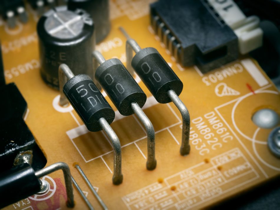
A diode is made from a piece of semiconductor material, usually silicon, that is doped to create a P-N junction. The P-side, or anode, is doped with material to create an excess of holes (positive charge carriers), while the N-side, or cathode, is doped to create an excess of electrons (negative charge carriers). When a voltage is applied across the diode, current will flow from the anode to the cathode, but not in the other direction.
The most common type of diode is the silicon diode, which has a forward voltage drop of approximately 0.7 volts. This means that the diode will start conducting current when the voltage across it exceeds 0.7 volts. Silicon diodes are used in a wide range of applications, including power rectification and voltage clamping.
Some common types of diodes include:
Zener diodes are a special type of diode that can conduct current in the reverse direction when a specific reverse voltage, known as the Zener voltage, is reached. Zener diodes are often used in voltage regulation circuits to maintain a constant output voltage.
Light-emitting diodes (LEDs) are diodes that emit light when current flows through them. The color of the light depends on the energy gap of the semiconductor material used in the diode. LEDs are used in a wide range of applications, from indicator lights to display screens.
Schottky diodes have a lower forward voltage drop (typically 0.2 to 0.3 volts) and faster switching times than silicon diodes. They are often used in high-frequency applications, such as radio frequency circuits and power converters.
Diodes have various applications in electronic circuits. Some common uses include:
Rectification: Diodes can be used to convert alternating current (AC) to direct current (DC), a process known as rectification.
Voltage regulation: Zener diodes can be used to maintain a constant output voltage, regardless of changes in the input voltage or load conditions.
Signal demodulation: Diodes can be used to extract the information content from a modulated signal, such as a radio or television broadcast.
Light emission: LEDs can be used to produce light, making them a key component in a wide range of lighting and display applications.
Understanding the different types of diodes, their specifications, and their applications is essential for anyone working with circuit board components.
Transistors
Transistors are a type of semiconductor device that can amplify or switch electronic signals and electrical power. They are one of the basic building blocks of modern electronic devices and are commonly found on circuit boards.
A transistor consists of three layers of semiconductor material, creating two P-N junctions. The three layers are typically labeled as the emitter, base, and collector. Depending on the arrangement of the P-type and N-type semiconductors, transistors can be classified as either NPN or PNP type.
The operation of a transistor relies on the control of current through the device. A small current entering the base is amplified to produce a larger collector and emitter current. This property makes transistors useful for amplification and switching applications.
There are several types of transistors, each with its specific characteristics and applications. Some common types of transistors include:
Bipolar Junction Transistors (BJTs) are the most common type of transistor. They are used in a wide range of applications, from signal amplification to switching. BJTs come in two types: NPN and PNP.
Field-Effect Transistors (FETs) control the electrical behavior of a device using an electric field. FETs are divided into Junction-Gate Field-Effect Transistors (JFETs) and Metal-Oxide-Semiconductor Field-Effect Transistors (MOSFETs). FETs are commonly used in applications such as signal amplification and switching.
Darlington Transistors are a pair of BJTs connected in a configuration that allows for higher current and power gain. They are often used in applications that require a significant amount of current.
Transistors have various applications in electronic circuits. Some common uses include:
Amplification: Transistors can amplify a small input signal into a larger output signal. This makes them essential in applications such as audio amplification and signal processing.
Switching: Transistors can act as a switch, controlling a large current with a small input signal. This property is used in digital logic circuits and power control applications.
Voltage regulation: Transistors can be used in voltage regulation circuits to maintain a constant output voltage.
Oscillation: Transistors can be used in oscillators, circuits that generate a continuous output waveform.
Understanding the different types of transistors, their specifications, and their applications is essential for anyone working with circuit board components.
Recommended Reading: How Do Circuit Boards Work: A Comprehensive Guide to the Heart of Electronics
Circuit Board Design and Layout
The design and layout of a circuit board is a critical step in the creation of electronic devices. It involves arranging the components and wiring them together in a way that achieves the desired functionality while minimizing space, cost, and potential interference between components.
The process begins with the creation of a schematic diagram, which is a symbolic representation of the circuit. The schematic shows all the components and how they are connected, but it does not represent the physical layout of the board.
Once the schematic is complete, the next step is to create the physical layout of the board. This involves placing the components on a virtual representation of the board and routing the connections between them. The layout must take into account the physical size and shape of the components, the space available on the board, and the need to minimize the length and crossing of connections to reduce potential interference.
The layout process also involves the creation of layers. Most circuit boards are multi-layered, with separate layers for power, ground, and signal connections. The layers are separated by insulating material and connected where necessary by vias, which are small holes filled with conductive material.
Once the layout is complete, it is converted into a format that can be used by a machine to manufacture the board. This usually involves creating a series of images or files that represent the layout of each layer, the locations of the holes to be drilled, and any text or graphics to be printed on the board. These files are commonly known as Gerber Files. [5]
Circuit Board Schematics
Circuit board schematics are a crucial part of the design and layout process. They provide a detailed map of how the components of a circuit are interconnected. Schematics are typically created using computer-aided design (CAD) software, which allows for precise placement and routing of components.
A schematic diagram uses standardized symbols to represent the various components of a circuit. For example, resistors are represented by a zigzag line, capacitors by two parallel lines, and transistors by a combination of lines and circles. Lines connecting the symbols represent the electrical connections between the components.
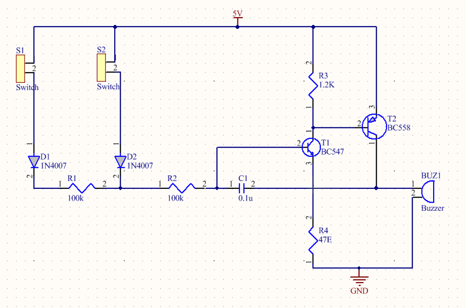
In addition to the symbols for the components, a schematic diagram also includes information about the values or specifications of the components. For example, a resistor symbol might be accompanied by a value in ohms, and a capacitor symbol by a value in farads.
Schematics also include information about the power supply and ground connections, as well as any input and output connections. They may also include notes or labels to provide additional information or clarification.
Creating a clear and accurate schematic is a critical step in the design of a circuit board. It serves as a guide for the layout process and provides a reference for troubleshooting and modifications. It also serves as a record of the design, which can be useful for future revisions or related projects.
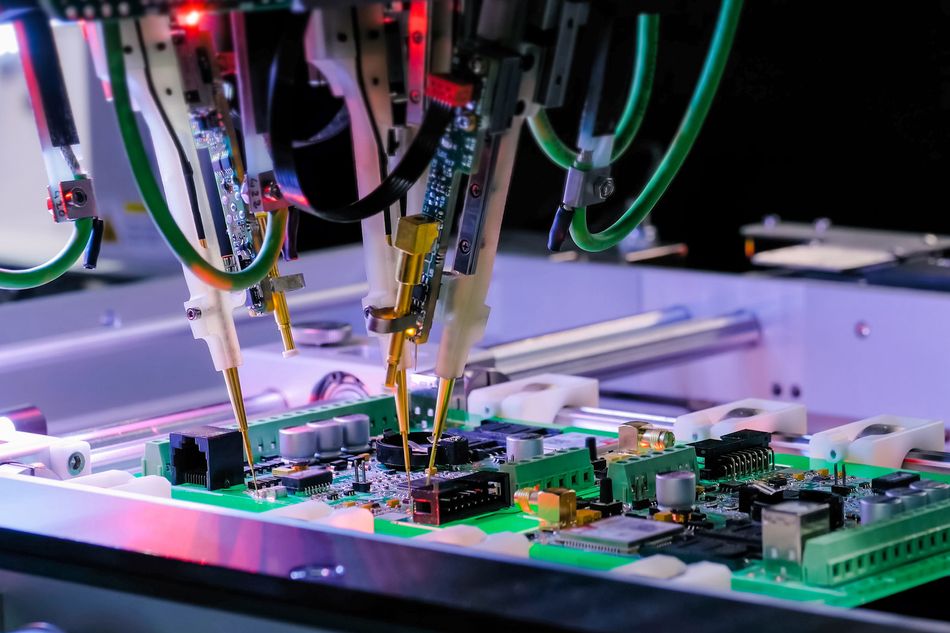
Circuit Board Assembly
Circuit board assembly is the process of attaching and soldering components onto a printed circuit board (PCB). This process transforms the PCB from a bare board into a fully functional electronic device.
The assembly process begins with the application of solder paste to the PCB. The solder paste is a mixture of tiny solder particles and flux, which helps the solder flow and bond to the metal surfaces. The paste is applied to the areas of the PCB where the components will be attached, typically using a stencil to ensure precise application.
Next, the components are placed onto the PCB. This is often done using a machine called a pick-and-place machine, which uses a vacuum nozzle to pick up the components and accurately place them onto the solder paste on the PCB. The components used in this process range from resistors, capacitors, and inductors to more complex ICs and connectors.
Once all the components are in place, the PCB is heated in a reflow oven. The heat causes the solder paste to melt and form a solid connection between the components and the PCB. The temperature profile in the reflow oven is carefully controlled to ensure that the solder melts and solidifies correctly without damaging the components.
After reflow, the PCB may undergo additional processes, such as the soldering of through-hole components or the application of a protective coating. The assembled board is then inspected, often using automated optical inspection (AOI) or X-ray inspection to check for defects such as missing or misaligned components, insufficient solder, or solder bridges.
Finally, the assembled board is tested to verify its functionality. This can involve applying power and signals to the board and measuring the response, or using a device called a bed of nails tester to make contact with multiple points on the board simultaneously.
PCB assembly is a complex process that requires precision and control. Understanding this process is essential for anyone involved in the design or production of electronic devices.
Recommended Reading: How to Design a PCB Layout: A Comprehensive Guide
Troubleshooting Circuit Board Components
Troubleshooting circuit board components is a critical skill in electronics. It involves identifying and resolving issues that prevent a circuit board from functioning correctly. This process can be complex, as it requires a deep understanding of the circuit's design and operation, as well as the ability to use various testing and diagnostic tools.
One common troubleshooting method is visual inspection. This involves examining the circuit board for visible signs of damage or failure, such as burnt components, cracked solder joints, or bulging capacitors. A magnifying glass or microscope may be used to inspect small or densely packed components.
Another common method is signal tracing. This involves following the path of a signal through the circuit, using a tool such as an oscilloscope or logic analyzer to observe the signal at various points. If the signal is not as expected at a certain point, the components along the path can be checked for faults.
Power supply issues are a common cause of circuit board problems. This can include issues such as insufficient power, excessive noise, or unstable voltages. Power supply issues can often be identified using a multimeter to measure the voltage and current at various points in the circuit.
Short circuits and open circuits are another common issue. A short circuit, where a connection is made that should not be, can cause excessive current flow and potentially damage components. An open circuit, where a connection is missing, can prevent current from flowing where it should. These issues can often be identified using a continuity tester or ohmmeter.
Testing Circuit Board Components
PCB prototyping refers to the process of creating a preliminary version of a PCB design to test its functionality and feasibility before committing to mass production. It involves checking each component individually to verify that it is functioning correctly.
Resistors can be tested using an ohmmeter, which measures resistance. The measured resistance should be compared to the specified value for the resistor, allowing for a certain amount of tolerance.
Capacitors can be tested using a capacitance meter or digital multimeter, which measures capacitance. Like resistors, the measured capacitance should be compared to the specified value. In addition, capacitors can be checked for leakage current using an insulation resistance tester. [6]
Diodes and transistors can be tested using a multimeter with a diode test function. This measures the forward voltage drop of the diode or transistor, which should be within a certain range. In addition, the diode or transistor should not conduct in the reverse direction.
Integrated circuits can be more difficult to test, as they often contain many internal components and connections. However, they can often be tested by applying inputs and checking the outputs, or by using a specialized tester if one is available.
Testing circuit board components requires a good understanding of the components and their specifications, as well as the ability to use various testing tools. It is a critical step in troubleshooting and repairing circuit boards.
Recommended Reading: PCB Testing: PCB Testing: A Comprehensive Guide to Techniques, Tools, and Best Practices
Conclusion
Understanding circuit board components is crucial in electronics, for hobbyists, engineers, and students alike. Knowledge of components like resistors, capacitors, diodes, and transistors is fundamental for designing, troubleshooting, and improving electronic devices. Understanding their roles, specifications, and circuit board design and assembly is crucial for innovation and the development of advanced technological solutions. This also aids in creating more efficient and reliable circuits, leading to improved performance and longevity of the devices we use daily.
Frequently Asked Questions (FAQs)
Q: What is the difference between active and passive components?
A: Active components, such as transistors and integrated circuits, can amplify or switch electronic signals, while passive components, such as resistors, capacitors, and inductors, cannot. Passive components control the flow of electricity but do not produce energy.
Q: How do I read the color codes on resistors?
A: Each color on a resistor corresponds to a specific number, and the sequence of colors indicates the resistor's resistance value in ohms. There are online tools and charts available to help you decipher the color codes.
Q: What is the purpose of a capacitor in a circuit?
A: Capacitors store electrical energy in an electric field and can release it when needed. They are used for various purposes, such as filtering, energy storage, and coupling or decoupling signals.
Q: How do I test a diode?
A: Diodes can be tested using a multimeter with a diode test function. This measures the forward voltage drop of the diode, which should be within a certain range. In addition, the diode should not conduct in the reverse direction.
Q: What is the difference between NPN and PNP transistors?
A: NPN and PNP transistors are two types of bipolar junction transistors. The main difference between them is the arrangement of the P-type and N-type semiconductor materials. In an NPN transistor, the base is made of P-type material sandwiched between two N-type materials, while in a PNP transistor, the base is made of N-type material sandwiched between two P-type materials.
References
[1] Medium. What is a PCB and Intro to PCB Design [Cited 2024 January 18] Available at: Link
[2] Jhdpcb. PCB Type [Cited 2024 January 18] Available at: Link
[3] Arrow. How to read Resistor Color Code [Cited 2024 January 18] Available at: Link
[4] Byjus. Inductance - Self Inductance and Mutual Inductance [Cited 2024 January 18] Available at: Link
[5] Wevolver. What are Gerber Files? Understanding the Blueprint of Electronics Manufacturing [Cited 2024 January 18] Available at: Link
[6] Fluke. How to Measure Capacitance [Cited 2024 January 18] Available at: Link