Current Divider: Comprehensive Guide to Theory, Design, and Implementation
This article explores the theory, design, and practical applications of the current divider in electrical engineering, covering resistive, reactive, and transistor-based implementations for accurate current control and distribution.

04 Nov, 2025. 17 minutes read
Current Divider Rule or Current Division Circuit
Introduction
Modern electronics rely on precise control of currents, whether biasing an amplifier, distributing supply currents among loads or measuring unknown currents. The current divider circuits, networks that split a source current into separate paths, play a central role in these tasks. In contrast with voltage dividers, which allocate voltage across series resistances, a current divider uses parallel branches to distribute current according to each branch’s resistance. Understanding how current divides and being able to calculate branch currents is essential for digital and hardware engineers when designing power distribution, analog front‑ends or sensor interfaces.
This article explores the complete theory, mathematical derivation, design equations, and real-world implementation of current dividers across both passive and active circuits, equipping engineers with the analytical and practical skills required for robust electronic system design.
Fundamentals of Current Divider Circuits
What is a Current Divider?
A current divider is a parallel circuit in which the total supply current splits among multiple branches. Each branch shares the same voltage (because all components connect across the same nodes), but different currents flow through each component due to differences in resistance.
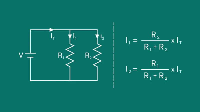
In a two‑branch divider with resistors R1 and R2, the source current divides into branch currents such that:

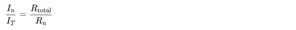
The current divider rule (CDR) states that the current through a branch is inversely proportional to its resistance relative to the total resistance of the parallel network. [1] That means the branch with the smallest resistance carries the largest share of current. Because the voltage across every branch is the same, branch currents can be found directly using Ohm’s law (V = I x R) once the voltage is known.
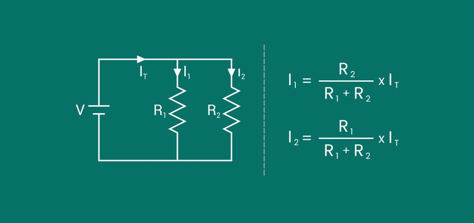
In the figure above, a current source feeds two resistors in parallel, producing branch currents I1 and I2.
Derivation of the Current Divider Rule
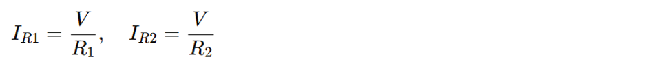
To derive the CDR for two resistors, consider a parallel combination of R1 and R2 connected across a supply with total current. The voltage across both resistors is V. From Ohm’s law,
and for the parallel network:

Substituting and simplifying yields the current divider formulas:
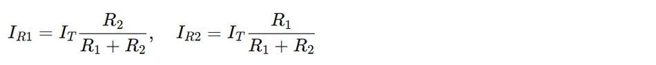
Each branch current contains the resistance of the other branch in its numerator, reflecting the inverse relationship between resistance and current.
This extends to n parallel branches! For an n-branch current divider, the total current is:
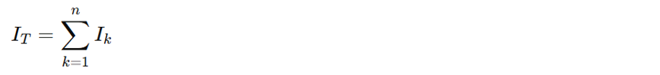
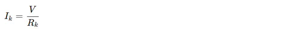
Each branch shares the same voltage V, and using Ohm’s law:
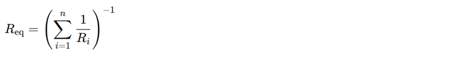
The equivalent parallel resistance is:
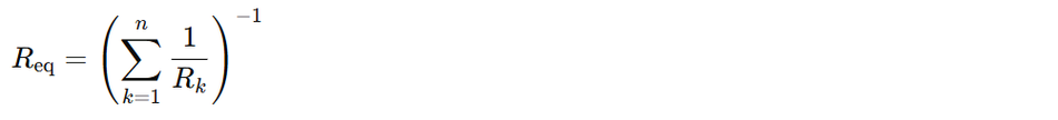
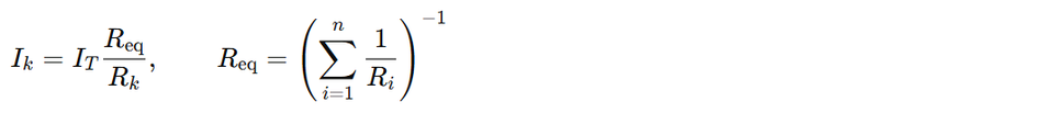
Combining these gives the general current divider equation:

Thus, each branch current equals the total current multiplied by the ratio of the equivalent (parallel) resistance to that branch resistance.
Relationship to Voltage Divider
It’s common to confuse the current divider and voltage divider relationships. Both distribute an electrical quantity among components using resistance ratios, but in opposite configurations.
In a voltage divider, the ratio involves:
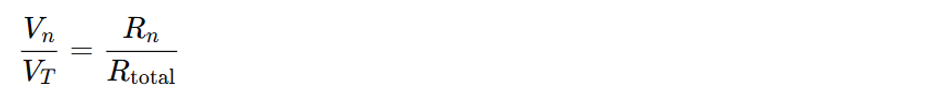
whereas in a current divider, it is:
Remembering this inversion prevents the incorrect use of the voltage divider rule when analyzing parallel circuits. Both results yield ratios less than one because they divide a total value among multiple elements.
Why Current Dividers Matter?
Current dividers are fundamental building blocks in electronic circuits for several reasons:
Biasing and Signal Distribution: In analog circuits and amplifiers, current dividers establish precise bias currents or split reference currents among multiple transistors or branches.
Instrumentation: Current divider circuits with shunt resistors enable safe current measurement by diverting most current through the shunt, protecting meters and sensors.
Power Sharing: In power electronics, parallel resistors or loads share current to balance electrical and thermal stress across components.
Digital Interfacing: Current division helps distribute and limit currents among multiple logic inputs or integrated circuits (ICs), improving signal integrity in mixed-signal designs.
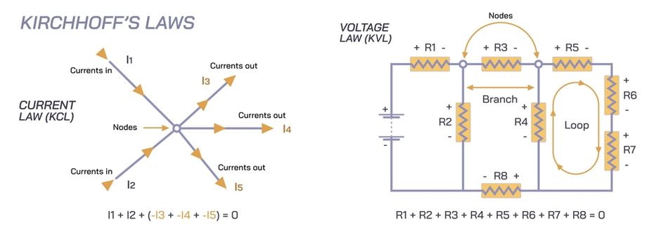
Education and Analysis: The concept demonstrates Kirchhoff’s current law and Ohm’s law, helping students analyze parallel resistive circuits effectively.
In summary, current divider circuits form the foundation of parallel circuit analysis, illustrating how total current splits among branches based on resistance. Their understanding is essential for accurate and efficient electronic design.
Recommended Reading: Parallel vs Series Circuits: Differences, Theory, and Practical Applications
Methods for Calculating Branch Currents
Standard Resistance‑Based Formula
The most common way to determine branch currents in a current divider is through the resistance-based expression derived from Ohm’s law and Kirchhoff’s current law. [2]
For a two-branch parallel circuit containing resistors R1 and R2, the total current divides as:

The resistor in the opposite branch appears in each numerator, illustrating that current is inversely proportional to resistance.
For n parallel resistors, the general current divider rule is expressed as:
This formulation requires finding the equivalent resistance of the parallel combination before evaluating each branch current.
Conductance Method
The alternative approach employs conductance, the reciprocal of resistance, defined as:

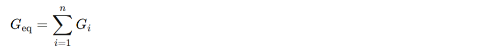
In this representation, higher resistance values correspond to lower conductance, and vice versa. For a parallel network, the total conductance equals the sum of individual conductances:
The branch current can then be written as:

Here, each branch current is directly proportional to its conductance rather than inversely proportional to its resistance. This conductance-based form is often preferred when working with extremely large or small resistor values, such as in analog or precision measurement circuits, where conductance is expressed in Siemens (S) or milli-Siemens (mS) units.
Using the Current Divider Rule in Practice
To apply the current divider rule (CDR) correctly:
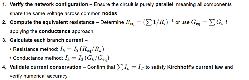
Following these steps ensures precise analysis of current flow and current division in multi-branch electrical circuits, a cornerstone of both analog and digital circuit design.
Recommended Reading: Types of Circuits: A Comprehensive Guide for Engineering Professionals
Worked Examples
Two‑Branch Current Divider Example
Problem: A 20 Ω resistor is connected in parallel with a 60 Ω resistor across a 30 V supply. Find the current through each resistor and the total supply current.
Step 1 — Compute the Equivalent Resistance of the Parallel Circuit
For two parallel resistors, R1 = 20Ω and R2 = 60Ω:

This equivalent resistance is the parallel combination seen by the source.
Step 2 — Find the Total Current from the Source using Ohm’s Law

Step 3 — Find Branch Currents using the Current Divider Rule
For the 20 Ω branch:

For the 60 Ω branch:

Check using Ohm’s law directly on each resistor:

Verification with Kirchhoff’s current law (KCL):

The lower-resistance branch (20 Ω) carries three times the current of the higher-resistance branch (60 Ω). This illustrates the inverse resistance relationship defined by the current divider rule.
Multi‑Branch Divider and Conductance Example
Now consider three resistors in parallel: 10 kΩ, 4 kΩ, and 2 kΩ, all connected across a 100 V source. We will compute the branch currents and the total current, using both resistance and conductance views.
Step 1 — Compute Equivalent Resistance of the Parallel Network:


So the equivalent resistance is approximately 1.176 kΩ.
Step 2 — Total Current from the Source:

This is the total current drawn from the power supply.
Step 3 — Individual Branch Currents using Ohm’s Law (Direct Method):
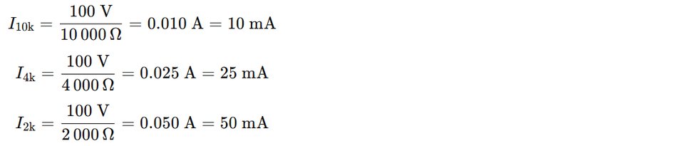
Check with KCL:

So, KCL holds: the sum of all branch currents equals the total current.
Step 4 — Same Result using Conductance Form of the Current Divider:
Define conductance for each branch:
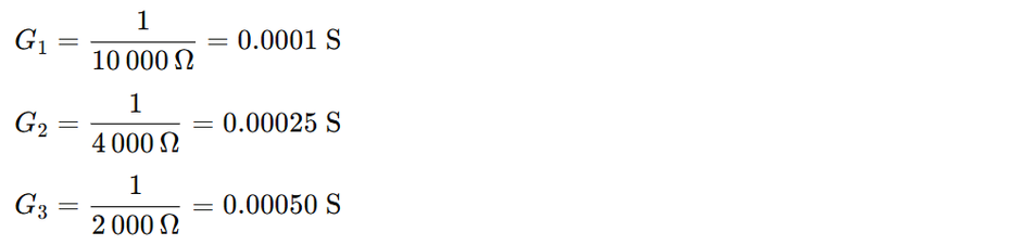
The total conductance:

Using the conductance form of the current divider equation for branch k:

For the 2 kΩ branch, for example:

This matches the Ohm’s law result. The conductance method is especially convenient in large parallel networks and high-precision analog design because conductances add directly in parallel.
Practical Implementation of Resistive Current Dividers
Construction Techniques
The way a current divider is built affects accuracy, repeatability and safety. The three common construction methods include:
Breadboard Implementation: Ideal for quick prototyping and tutorials. Components are inserted into a solderless breadboard, allowing rapid testing and easy modifications. However, parasitic capacitance and loose contacts may affect precision in high-frequency or low-current applications.
Terminal Strip Implementation: Offers a more stable and semi-permanent setup. Components and wiring are secured through screw terminals, providing reliable electrical contact. Care must be taken not to place more than two wires under one terminal to ensure professional wiring practices and minimize connection resistance.
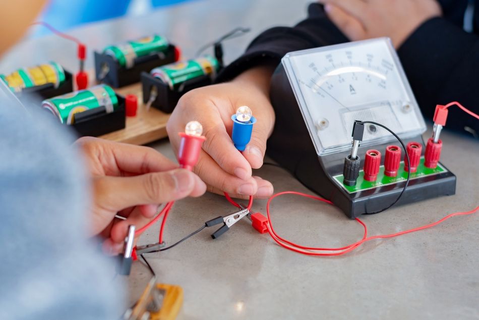
Free-Form (Alligator Clips): Components are connected using clips and jumper leads without a supporting base. This method is useful for conceptual demonstrations but is mechanically fragile and prone to electrical noise, making it unsuitable for long-term or production use. [3]
These methods demonstrate that current divider circuits can be assembled in various ways depending on the goal—proof‑of‑concept, measurement or final product.
Measurement Procedures
The accurate verification of a current divider requires careful lab measurement following Ohm’s law, Kirchhoff’s current law (KCL) and Kirchhoff’s voltage law (KVL) principles.
Follow the steps below:
Measure Branch Resistances: Use an ohmmeter to determine the actual resistance values of each branch resistor. Note any deviations from nominal ratings.
Assemble the Circuit: Connect the resistors in a parallel circuit across the supply voltage. Ensure all nodes share the same potential difference.
Verify Branch Voltage Equality: Measure the voltage across each branch using a voltmeter; all readings should match the source voltage.
Measure Branch and Total Currents: Insert an ammeter in each branch and one in series with the source to record branch currents and total current. The sum of individual branch currents should equal the total measured current, validating the current divider rule and the network’s integrity.
The measured values should align closely with theoretical calculations within the resistor tolerance range.
Non‑Ideal Considerations
In practical electrical circuits, several real-world factors cause deviations from ideal current division behavior. Engineers must account for these effects when designing precision analog or power supply systems.
Resistance Tolerance: Commercial resistors typically vary by ±0.1 % to ±5 %. Always measure actual resistance values before calculations to improve current accuracy.
Parasitic Effects: At higher frequencies, resistors exhibit small amounts of inductance and capacitance, altering the effective impedance of the circuit. Use low-inductance, wide-shunt resistors to minimize the skin effect and maintain predictable AC impedance.
Contact and Lead Resistance: In low-value shunt applications, the lead resistance and solder joints can be comparable to the resistor itself. Implement Kelvin (four-terminal) connections to separate current-carrying and voltage-sensing paths, minimizing measurement error.
Temperature and Power Dissipation: Self-heating due to I2R losses changes resistance and can cause drift. It is better to select resistors with low temperature coefficients (TCR) and ensure adequate power rating to prevent overheating and ensure long-term stability.
Current dividers are essential for precise current distribution and circuit stability in both analog and digital systems. Proper design, measurement, and construction ensure reliable performance and minimize real-world deviations.
Recommended Reading: PCB Components: A Comprehensive Technical Guide to Passive, Active, and Electromechanical Parts
Current Dividers in Instrumentation and Sensing
Shunt Resistors in Ammeters
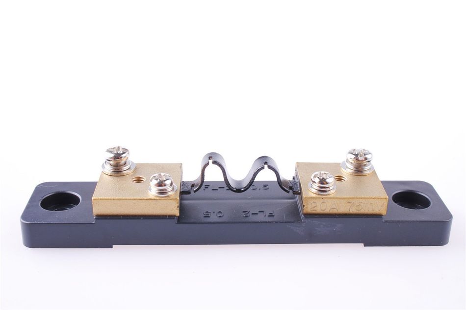
In analog instrumentation, an ammeter uses the current divider principle to extend its measurement range safely. A precision shunt resistor is placed in parallel with the meter movement coil, allowing most of the total current to bypass the sensitive meter mechanism.
The instrument measures the voltage drop across the shunt and, using Ohm’s law, infers the total current as:

Because the current divider circuit directs only a small fraction of the total current through the meter, this configuration protects the movement from overload.
Modern current-sense resistors are optimized for:
Ultra-low resistance (in the milliohm range) to minimize power loss,
High power rating for thermal reliability,
Low inductance for accurate high-frequency response, and
Stable temperature coefficient (TCR) for predictable performance over wide temperature ranges.
For accurate AC or transient measurements, designers use wide, flat metal-foil shunts that reduce skin effect and maintain consistent impedance. Additionally, four-terminal Kelvin connections separate current and sense paths, eliminating lead resistance errors common in two-terminal configurations.
Selecting a Shunt Resistor
Choosing the correct shunt resistor is critical for achieving precise current measurement and maintaining circuit integrity.
The key design considerations include:
Accuracy and Stability: Use precision resistors with tolerance ≤ 0.1 % and a low temperature coefficient (e.g., < 25 ppm/°C). Drift due to temperature or long-term aging can otherwise degrade the current divider’s linearity.
Inductance and Frequency Response: Low-inductance constructions such as flat metal elements or bulk-metal resistors prevent phase error and amplitude distortion in high-frequency or pulse applications.
Current Range and Power Dissipation: The resistor value should generate a measurable voltage drop (typically 50 mV–200 mV) at minimum current while safely dissipating heat under maximum load. Power rating must exceed I2R shunt with margin, and proper heat sinking or PCB copper area should be provided for thermal relief.
Physical Integration: Ensure mechanical stability and compatibility with the PCB layout. Shunts for surface-mount PCBs often feature wide terminations to reduce thermal gradients and improve reliability.
Placement Considerations
Current divider placement in the circuit significantly affects measurement accuracy and safety:
Low-Side Sensing: The shunt resistor is connected between the load and ground. This configuration keeps the measurement reference near zero potential, simplifying circuit design and enabling the use of low-cost op-amps or ADCs. It is preferred in battery-powered systems and IoT sensors where isolation is not critical.
High-Side Sensing: The shunt is placed between the supply and the load, allowing the system to monitor load faults, short circuits, or supply interruptions. However, this setup introduces common-mode voltage, requiring differential amplifiers or high-side current-sense ICs with high CMRR (Common-Mode Rejection Ratio) to maintain accuracy.
Proper trace routing and short sense paths are vital. Any unwanted voltage drop in the current path can distort readings. In precision systems, designers often apply Kelvin sense routing and guard traces to minimize interference and leakage currents.
Applications
Shunt-based current divider circuits are integral to a wide range of electrical and electronic systems:
Measurement Instruments: Used in analog ammeters, digital multimeters, and data acquisition systems to safely sense large currents.
Power Electronics and Supplies: Monitor load currents in switch-mode power supplies, industrial controllers, and automotive ECUs to regulate performance and detect overloads.
Motor Drives and Electric Vehicles: Used in motor control units (MCUs), battery management systems (BMS), and EV chargers to monitor current flow and ensure balanced power distribution.
Embedded and IoT Devices: Enable low-power current sensing in microcontrollers and analog front-ends for predictive maintenance and energy efficiency tracking.
PCB-Level Monitoring: Integrated current sense amplifiers and semiconductor sensors use current divider rules to create voltage feedback proportional to branch current, supporting closed-loop control in integrated circuits and smart sensors.
By applying the current divider formula, engineers can design circuits that divert a known, safe fraction of current through the measurement path without disturbing the overall system behavior.
Recommended Reading: How Do Circuit Boards Work: A Comprehensive Guide to the Heart of Electronics
Advanced Current Divider Circuits: Current Mirrors
Introduction to Current Mirrors
While resistive current dividers passively split current according to resistor ratios, active current dividers, known as current mirrors, use transistors to reproduce or scale a reference current with remarkable accuracy.
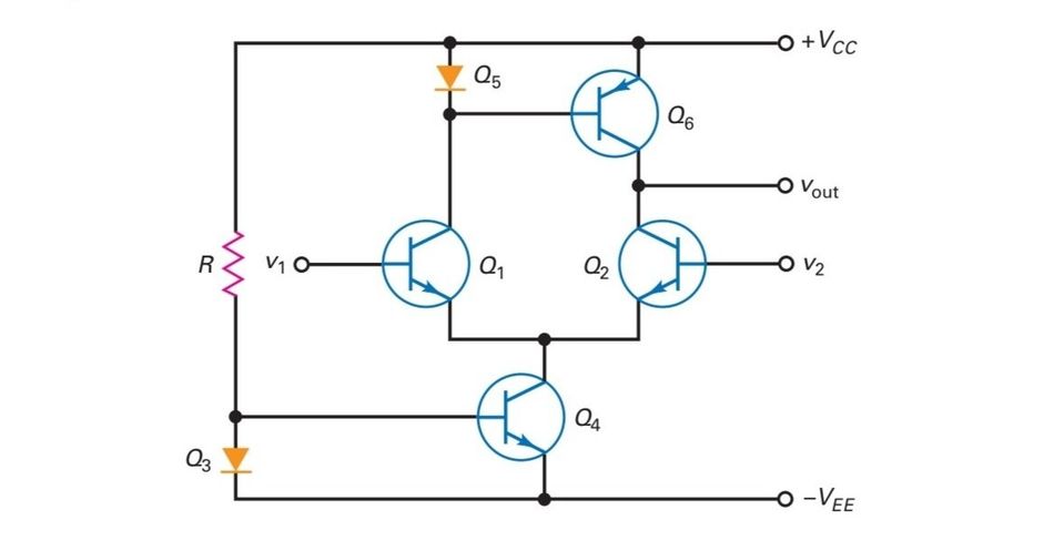
The current mirror replicates an input current as an output current that remains nearly constant over load-voltage variations. This behavior arises from the fact that two matched semiconductor devices (BJTs or MOSFETs) biased with equal base-emitter or gate-source voltages conduct equal currents at the same temperature.
Because of their high output resistance, current mirrors provide an output that is largely independent of the load voltage, unlike simple resistor-based current dividers, which depend on both load and supply conditions. Their low input impedance ensures accurate mirroring of the reference current, establishing a controlled current flow path crucial to analog circuit design.
Ratioed Current Mirrors
By adjusting device geometry or using multiple transistors, designers can scale output current relative to the input reference. If the emitter (or channel) area of the output transistor is N times larger than that of the reference device, the output current will ideally be N x I.
Conversely, arranging multiple transistors in parallel on the input side and fewer on the output side produces fractional scaling, effectively a current divider that outputs a defined portion of the input current. Such ratioed current mirrors are standard in integrated-circuit bias networks, where stable and predictable current ratios are required across temperature, voltage, and process variations.
Design Considerations
Transistor Matching – Mismatches in threshold voltage, mobility or geometry cause errors in current ratios. Layout techniques such as common‑centroid design, interdigitation and identical orientation mitigate mismatch.
Compliance Voltage – The current mirror requires a minimum voltage across the output transistor to maintain proper operation. If the load voltage drops below the compliance voltage, the mirror enters the triode region and the output current collapses.
Temperature Effects – Temperature variations affect transistor parameters; bias circuits often include negative feedback or temperature compensation to stabilize current.
Output Resistance – Finite output resistance means the output current will vary slightly with load voltage; cascading (adding extra transistors) increases output resistance and improves current stability.
Noise and Parasitics – Parasitic capacitances between collector/base or drain/gate terminals can limit frequency response. Proper layout symmetry and guard rings reduce noise coupling and maintain high-frequency accuracy.
Applications in Digital and Analog Design
Current mirrors are indispensable in analog integrated circuits because they replicate precise reference currents where simple resistors would be impractical due to chip-area and process variability. The key uses include:
Biasing Differential Pairs: Provide stable tail currents that set transconductance and gain in amplifiers.
Active Loads: Replace resistive loads in differential amplifiers to achieve high output impedance and maximize voltage swing.
Reference and Bias Distribution: Replicate a master current throughout an IC, maintaining consistent performance across multiple functional blocks.
Analog-to-Digital Converters (ADCs): Deliver precisely defined bias currents for sampling circuits and comparators.
Digital Logic and I/O Drivers: Ratioed mirrors generate controlled current sinks for off-chip drivers or on-chip biasing, ensuring uniform switching behavior.
By actively controlling current through matched transistors rather than passive resistors, current mirrors achieve superior precision, compactness, and temperature stability—making them the cornerstone of modern analog and mixed-signal circuit design.
Recommended Reading: Understanding Transistors: What They Are and How They Work
Design Guidelines and Considerations
Selecting Resistor Values
Choosing suitable resistor values for a current divider circuit requires balancing current ratios, power dissipation, and component tolerances. In a parallel circuit, a higher resistance value yields lower branch current, while a smaller resistance draws more current, as dictated by Ohm’s law.

For precision current division, use resistor values that create clean ratios — for example, 1 kΩ and 2 kΩ produce a 2:1 current ratio.
When the total current is fixed, the sum of branch currents is determined by the parallel resistance of the network:
Ensure the power supply can deliver the required total current without exceeding its rated capacity.
Power and Thermal Management
Each resistor in a current divider dissipates power according to:

Components must be rated comfortably above their worst-case power dissipation to prevent overheating. For high-current applications, use wire-wound, metal-film, or metal-oxide resistors with appropriate power ratings and low temperature coefficients (TCR).
Distribute heat evenly by physically spacing resistors and ensuring good airflow or heat sinking. In PCB layouts, use wide copper traces and thermal vias to reduce local hot spots and maintain uniform temperature across the divider network.
Mitigating Errors
To maintain accuracy in current divider circuits, several sources of error must be minimized:
Use Precision Components: Select resistors with tight tolerance (≤ 0.1 %) and low TCR to ensure consistent current division over temperature and voltage variations.
Account for Contact Resistance: In low-resistance shunt configurations, even small contact or lead resistances can cause measurement drift. Use four-terminal (Kelvin) connections to separate the current and voltage paths.
Consider Parasitic Effects: At higher frequencies, resistors exhibit parasitic inductance and capacitance that alter effective impedance. Use surface-mount chip resistors and short, parallel traces to minimize these effects in high-speed analog or RF designs.
Parallel Resistor Networks for Higher Power
When a single resistor cannot handle the desired current flow or power dissipation, multiple identical resistors can be connected in parallel. This configuration effectively increases total power capacity and reduces the equivalent resistance:

where N is the number of resistors used.
To ensure equal current sharing, choose resistors with closely matched resistance values and tolerances, and mount them symmetrically on the PCB to minimize thermal imbalance. This approach is common in power electronics, current sensing networks, and load-sharing applications.
Reactive Current Dividers
In AC circuits, current division is governed by impedance rather than resistance. Each branch may contain a resistor (R), a capacitor (C), or an inductor (L), and the total branch current depends on the complex impedance:

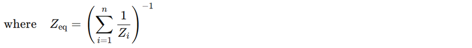
Because capacitive and inductive reactances cause phase shifts between current and voltage, phasor or complex algebra analysis is required to determine magnitude and phase relationships.
These reactive current dividers form the theoretical basis for:
Filter design (low-pass, high-pass, and band-pass networks),
AC power distribution and impedance matching,
Tuned amplifier circuits, and
Radio-frequency (RF) and signal-conditioning applications.
Proper application of these design guidelines ensures that current divider circuits, whether resistive or reactive, operate with high accuracy, thermal reliability, and predictable performance across both DC and AC domains.
Current Divider Applications in Digital and Hardware Engineering
Digital Logic and Mixed‑Signal Circuits
In digital and mixed-signal systems, current divider circuits are used to limit, bias, or distribute currents between interconnected analog and digital components. For example, a resistive current divider can generate a defined bias current for a comparator, analog-to-digital converter (ADC), or sensor interface. This ensures stable input biasing while protecting sensitive digital inputs from excessive current.
Engineers must verify that each branch current remains within device ratings and that the resulting voltage drop, determined by Ohm’s law, maintains valid logic-level thresholds (e.g., within TTL or CMOS input ranges). [4]
In low-power microcontroller systems, small current dividers are also used to provide pull-up or pull-down biasing, filtering analog noise, or setting input impedance in mixed-signal front-ends.
Bias Networks and Reference Generators
In analog circuit design, current dividers form the foundation of bias networks that establish operating points for amplifiers and transistor stages. By splitting a reference current into multiple controlled branches, designers can bias differential pairs, operational amplifiers, and transconductance amplifiers with predictable precision.
On integrated circuits, this function is often implemented using transistor-based current mirrors, which replicate or scale reference currents while maintaining temperature stability and process consistency. When designed correctly, these bias dividers maintain uniform branch currents across the chip, improving linearity and minimizing drift in analog signal paths.
Current Sharing in Power Electronics
In power electronics and hardware engineering, current dividers are essential for ensuring balanced current flow when multiple devices operate in parallel. Power MOSFETs, BJTs, or IGBTs connected in parallel require source (or emitter) resistors, also known as ballast resistors, to equalize current distribution.
Each resistor acts as a local current divider, introducing a small, controlled voltage drop, typically in the range of 10–50 mV at nominal load. This drop counteracts variations in transistor threshold voltage or transconductance, preventing any single device from hogging current and overheating.
Sensing in Industrial Control and IoT
Current dividers are widely used in industrial automation, embedded systems, and IoT applications for measurement, protection, and control. Below are their details:
In motor control and battery management systems (BMS), precision current sense resistors operate as shunt-based current dividers, allowing small, measurable voltage drops to represent large load currents. [5]
In sensor front-ends, they translate sensor currents into proportional voltages for microcontroller ADC inputs, enabling accurate current-to-voltage conversion.
In industrial equipment, current dividers provide real-time feedback for process monitoring, overcurrent protection, and load diagnostics.
Modern IoT platforms often combine low-ohmic resistors, operational amplifiers, and ADC modules to measure both DC and AC currents accurately while minimizing power loss and maintaining compact PCB footprints.
Recommended Reading: Transistor as a Switch: Theory and Practical Implementation for Digital and Hardware Engineers
Simulation, Testing, and Troubleshooting of Current Divider Circuits
Simulation Techniques
Before physically assembling a current divider circuit, engineers typically validate its performance through circuit simulation tools such as SPICE, LTspice, Multisim, or Proteus. Simulation enables accurate prediction of branch currents, voltage drops, and power dissipation without risking component damage or wiring errors.
Steps for SPICE simulation:
Model the Circuit: Create a schematic using realistic component models for resistors, capacitors, and inductors (for AC analysis). Include the current source or voltage source as required.
Perform DC Analysis: Evaluate steady-state current flow and confirm the validity of the current divider rule. Compare the simulated branch currents with analytical results derived from Ohm’s law.
Run Parametric Sweeps: Vary resistor values or input voltage to test sensitivity and tolerance effects.
Conduct Transient or AC Analysis: Observe how reactive components (capacitors and inductors) affect impedance and phase relationships under different frequencies.
Simulation results can be plotted as current versus time, frequency, or resistance value, providing a visual understanding of circuit behavior under diverse operating conditions.
Testing and Validation Procedures
The current divider must be verified experimentally after the simulation phase. Proper testing ensures the circuit behaves as designed under real-world conditions.
The testing workflow is as follows:
1. Resistance Verification: Measure the actual resistance of each branch using a digital multimeter (DMM) or Ammeter. Record the values, as even small tolerance deviations can alter the current distribution.
2. Circuit Assembly: Construct the parallel circuit on a breadboard, PCB, or terminal strip, depending on the stage of testing. Ensure solid electrical connections and minimal contact resistance.
3. Voltage and Current Measurement:
Use a voltmeter to verify identical voltage across all parallel branches.
Use an ammeter or current probe in each branch to measure branch currents directly.
Confirm that the sum of branch currents equals the total current, in line with Kirchhoff’s current law (KCL).
4. Temperature Check: Monitor component temperature using an infrared thermometer or thermal camera to ensure no resistor exceeds its power rating (P = I²R).
For AC or pulsed signals, use an oscilloscope with a current probe to visualize waveforms, phase shifts, and transient responses. Comparing experimental traces to SPICE plots confirms model accuracy.
Common Issues and Troubleshooting
Even well-designed current divider circuits can exhibit performance deviations due to practical imperfections. The following table summarizes frequent problems and corrective measures:
| Issue | Possible Cause | Solution |
| Unequal Branch Currents | Resistor Tolerance Mismatch or Poor Solder Joints | Replace with Matched Precision Resistors; Re-Solder Connections |
| Unstable Readings | Loose Wiring, Contact Resistance, or Thermal Drift | Use Low-Resistance Connectors, Stable Temperature Environment |
| Excessive Power Dissipation | Incorrect Resistor wattage or lower-than-expected Equivalent Resistance | Increase Resistor Rating or Number of Parallel Resistors |
| Frequency-Dependent Errors | Parasitic Inductance/Capacitance in Layout | Use Surface-Mount Components; Minimize Lead Length |
| Incorrect Total Current | Measurement or Wiring Error | Recheck Connections, Polarity, and Measurement Device Calibration |
Proper debugging relies on systematic isolation, measuring one branch current at a time and comparing it to theoretical expectations from Ohm’s law and the current divider formula.
Recommended Reading: Understanding Multimeter Symbols: A Comprehensive Guide for Engineers
Conclusion
Current dividers remain fundamental to modern electronics, providing a reliable means to control, distribute, and measure current across complex networks. Rooted in Ohm’s law and Kirchhoff’s current law, they form the backbone of biasing, sensing, and power-sharing applications. From resistive dividers and conductance-based methods to active current mirrors, these circuits ensure stable operation across analog, digital, and mixed-signal systems. Practical design requires careful attention to resistor tolerance, thermal management, and parasitic effects. Whether in industrial controls, IoT sensors, or integrated circuits, mastering current divider principles empowers engineers to achieve precision, efficiency, and reliability in every electrical design.
Frequently Asked Questions (FAQs)
1. What is a current divider, and how does it differ from a voltage divider?
A. A current divider in DC circuits splits total current among parallel-connected branches based on their resistances. The voltage divider follows KVL (Kirchhoff's Voltage Law), distributing volts across individual resistors in series where total resistance determines proportional voltage drops.
2. Why does the smaller resistor carry more current in a current divider?
A. Current is inversely proportional to resistance (Ohm’s law). In a parallel-connected network, the smaller resistor draws a greater share of total current because its lower resistance allows higher current flow.
3. When should I use the conductance method instead of the resistance method?
A. In electrical engineering, the conductance method is ideal when handling very large or small resistance total values or multiple branches, since conductances add directly in parallel circuits, simplifying current flow and analytical computation.
4. How are current dividers used in measuring instruments?
A. In DC circuits, shunt resistors act as current dividers that bypass most of i total, limiting current through sensitive meters. By measuring the voltage drop (volts) across the shunt, Ohm’s law provides accurate current readings.
5. What is a current mirror, and how does it relate to current dividers?
A. A current mirror is an active electrical engineering circuit using transistors to replicate or scale i total as output individual currents. It functions like a precise current divider, maintaining constant current regardless of load voltage variations.
References
[1] Fiveable. Current Divider Rule - (Electrical Circuits and Systems I) [Cited 2025 October 28] Available at: Link
[2] Keysight. Current Divider Formula - Used Keysight Equipment [Cited 2025 October 28] Available at: Link
[3] US Department of War. Chapter 8 Automotive Electrical Circuits and Wiring [Cited 2025 October 28] Available at: Link
[4] SparkFun Electronics. TTL Logic Levels [Cited 2025 October 28] Available at: Link
[5] TI. Shunt-Based Current-Sensing for BMS in HEVs/EVs [Cited 2025 October 28] Available at: Link
in this article
1. Introduction2. Fundamentals of Current Divider Circuits3. Methods for Calculating Branch Currents4. Worked Examples5. Practical Implementation of Resistive Current Dividers6. Current Dividers in Instrumentation and Sensing7. Advanced Current Divider Circuits: Current Mirrors8. Design Guidelines and Considerations9. Current Divider Applications in Digital and Hardware Engineering10. Simulation, Testing, and Troubleshooting of Current Divider Circuits11. Conclusion12. Frequently Asked Questions (FAQs)13. References