Resistor Chart: Comprehensive Guide to Resistor Values, E-Series, and Color Codes
A comprehensive resistor chart guide for digital design and hardware engineers. Explore resistor values, tolerances, units, E-series standard values, resistor color code systems, and practical resistor selection examples.

09 Apr, 2025. 14 minutes read
Key Takeaways
Resistors in Circuits: Resistors are fundamental electronic components used to limit current and divide voltage in electronic circuits. They are measured in ohms (Ω), with kilo-ohms (kΩ) and mega-ohms (MΩ) denoting thousands and millions of ohms.
Standard Values (E-Series): Industry-standard resistor values are organized into E-series (E6, E12, E24, E48, E96, E192), each specifying a set number of preferred values per decade (e.g., 12 values per decade for E12). These series correspond to typical tolerances (e.g., E12 for ±10%, E24 for ±5%, E96 for ±1%). Designers use these resistor charts to select the nearest standard value for a required resistance.
Resistor Tolerance: The tolerance of a resistor (e.g., ±5%, ±1%) indicates its possible variance from the labeled value. Wider tolerance parts (5%, 10%, 20%) use fewer standard values (E6/E12/E24 series), while precision resistors (±2%, ±1% or better) use the finer E48/E96/E192 series .
Color Code Chart: Through-hole resistors use a color band code to denote values. The resistor color code chart maps colors to digits and multipliers so you can read 4-band (two digits, multiplier, tolerance), 5-band (three digits, multiplier, tolerance), or 6-band (adds temperature coefficient) resistors at a glance.
Practical Usage: In practice, engineers reference resistor charts when designing circuits – e.g. choosing a 10 kΩ pull-up resistor for a logic input (a common default value balancing noise and power), picking two standard resistors to form a desired voltage divider ratio, or selecting an LED current-limiting resistor close to the calculated value.
Introduction
Resistors are one of the most common components in electronics, present in virtually every circuit design. A resistor’s job is to oppose the flow of electric current, allowing designers to control current and voltage in a circuit. Key uses of resistors include:
Limiting current (to protect components from excessive flow)
Creating voltage dividers to obtain different voltage levels.
Because resistors are so ubiquitous and vital – from simple LED circuits to complex digital systems – it’s important for engineers and students to understand how resistor values are specified and identified.
A resistor’s value is measured in ohms (Ω), the SI unit of electrical resistance named after Georg Ohm. In real-world usage, we encounter resistances spanning an extremely large range, so prefixes are used for convenience: 1 kΩ = 1,000 Ω and 1 MΩ = 1,000,000 Ω.
For example, a 4.7 kΩ resistor is 4700 ohms. Resistors can be as small as fractions of an ohm or as high as millions of ohms; values from a few milliohms (mΩ) up to gigaohms (GΩ) are manufactured for different applications. To manage this wide range of possibilities, standardization systems and charts are used to categorize resistor values and help designers pick appropriate components easily.
Suggested Reading: SMD Resistor Sizes: A Comprehensive Guide for Engineers
What is a Resistor Chart?
One common reference is a resistor chart, which provides a quick guide to standard resistor values and color codes. These charts are invaluable for identifying resistor markings (like color bands) or for selecting the nearest standard value during circuit design. In this article, we provide a comprehensive resistor chart guide covering both the theoretical concepts and practical implementations:
Resistor values, units, and tolerances
Structured E-series system
Resistor color code system with decoding examples
Practically choosing resistor values for specific applications
By the end, you should be comfortable reading any resistor color code, using resistor charts to find standard values, and selecting the right resistor for your designs.
Resistor Values, Units, and Tolerances
Resistor Value
It is the electrical resistance that a resistor provides, measured in ohms (Ω). According to Ohm’s Law, the voltage (V) across a resistor equals the current (I) through it times its resistance (R): V = I·R. Thus, a resistor’s value directly determines how much it will resist current for a given voltage.
For instance, a 100 Ω resistor will allow 0.1 A of current under 10 V, whereas a 1000 Ω (1 kΩ) resistor under the same voltage lets only 0.01 A flow.
Resistance Units and Notation
Because resistor values span many orders of magnitude, engineers use kilo-ohms and mega-ohms for convenience. 1 kΩ = 10^3 Ω and 1 MΩ = 10^6 Ω . It’s common to see notations like “4k7” to mean 4.7 kΩ or “1M0” for 1.0 MΩ in component labeling. This shorthand helps avoid confusion with decimal points (for example, 4R7 means 4.7 Ω, and 4K7 means 4.7 kΩ as per BS 1852 coding).
Resistor Tolerance
Real resistors are not exactly their nominal value; they have a manufacturing tolerance. Tolerance is given as a ±percentage that indicates how far off the actual resistance could be from the labeled value.
For example, a 1 kΩ ±5% resistor could measure anywhere between 950 Ω and 1050 Ω in reality. Common tolerance classes are ±20%, ±10%, ±5%, ±2%, ±1%, down to very tight ±0.1% or less for precision resistors. A 5–10% variance is usually acceptable in general-purpose circuits, but high-precision analog or filter circuits might require 1% or 0.1% resistors. The tolerance has a direct relationship with the available standard values: wider tolerance resistors are made in fewer, more widely spaced values, while tight tolerance resistors come in finer increments of values.
Recommended Reading: PCB Components: A Comprehensive Technical Guide to Passive, Active, and Electromechanical Parts
Standard Resistor E-Series (E6, E12, E24, E48, E96, E192)
Because producing every possible resistance value is impractical, the industry uses preferred values grouped into E-series. The E-series (specified in IEC 60063) designates certain standard resistor values in each decade (powers of ten). The letter “E” is followed by a number indicating how many values per decade that series contains. The most common series for resistors are:
E6 series: 6 values per decade, typically for ±20% tolerance resistors.
E12 series: 12 values per decade, for ±10% tolerance.
E24 series: 24 values per decade, for ±5% tolerance.
E48 series: 48 values per decade, for ±2% tolerance.
E96 series: 96 values per decade, for ±1% tolerance.
E192 series: 192 values per decade, for ±0.5%, ±0.25%, ±0.1% (ultra precision) .
Each successive series has roughly double the number of values of the previous, corresponding to narrower tolerance. In other words, an E-series defines how many distinct resistor values exist between 1 and 10 (the next decade repeats the pattern multiplied by 10, and so on).
For example, the E6 series (20% tolerance) uses about one value for each large range of variance – roughly spaced by a factor of ~1.5. The E12 (10%) series has smaller jumps, roughly a factor of ~1.21 between adjacent values. By the time we get to E96 (1% resistors), the steps are very fine (~1.05x increments).
Table 1: Standard Resistor Values in E6, E12, E24 Series (1–10 Ω decade)
Series (Tol.) | Values per Decade | Standard Values (Ω from 1 to 10) |
E6 (±20%) | 6 | 1.0, 1.5, 2.2, 3.3, 4.7, 6.8 |
E12 (±10%) | 12 | 1.0, 1.2, 1.5, 1.8, 2.2, 2.7, 3.3, 3.9, 4.7, 5.6, 6.8, 8.2 |
E24 (±5%) | 24 | 1.0, 1.1, 1.2, 1.3, 1.5, 1.6, 1.8, 2.0, 2.2, 2.4, 2.7, 3.0, 3.3, 3.6, 3.9, 4.3, 4.7, 5.1, 5.6, 6.2, 6.8, 7.5, 8.2, 9.1 |
For higher-precision series (E48, E96, E192), the list is extensive. E48 (±2%) includes values like 1.00, 1.05, 1.10, 1.15, 1.21, ... up to 9.53 in the 1–10 Ω range,
E96 (±1%) has an even denser set (starting 1.00, 1.02, 1.05, 1.07, 1.10, 1.13, ... approximately every 1% step).
The E192 series essentially covers almost every 0.5% step. It’s rare for designers to need E192 except in very critical applications.
Most design needs are met by E12 and E24 series resistors, which are the most common in industry.
How to use the E-series
Example 1: Suppose calculations suggest you need a 107 Ω resistor. You consult an E12 resistor chart (for 10% tolerance parts) and see values like 100 Ω and 120 Ω but not 107 Ω. You’d pick the closest standard value, 100 Ω (or 110 Ω if using E24 5% series). This ensures your design sticks to readily available resistors. If you truly need 107 Ω exactly, you might opt for a 1% resistor from the E96 series where 107 Ω (or very close, 107 Ω is likely included) is available.
Example 2: As another example, a 100 Ω ±20% resistor could measure between 80 Ω and 120 Ω; its E6 neighbors (the adjacent standard values in the E6 20% series) are 68 Ω and 150 Ω, which correspond to 20% low and high extremes of 100 Ω. This demonstrates how the E-series values are spaced according to tolerance – so that ranges overlap and cover the continuum of possible real values.
The E-series system greatly simplifies inventory and design. Manufacturers produce resistors mostly at these preferred values, and engineers design around them. Sticking to the “common” values in your resistor chart means your parts will be easier to source and more cost-effective.
Resistor Color Code System (4-Band, 5-Band, 6-Band)
Through-hole resistors (the cylindrical ones with leads) typically don’t have printed numbers. Instead, they use the electronic color code – a system of colored stripes on the body of the resistor to indicate value and tolerance. This color code is a universal standard, and a resistor color chart is used to decode the values. Being able to read the color bands is a crucial skill for any electronics engineer or student.
Color Code Basics
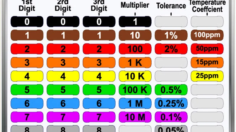
Each color corresponds to a number 0 through 9, a multiplier, or a tolerance as per the following table:
Band Color | Digit Value (Significant Figure) | Multiplier (Decimal Decade) | Tolerance (%) |
Black | 0 | ×1 (10⁰) | |
Brown | 1 | ×10 (10¹) | ±1 |
Red | 2 | ×100 (10²) | ±2 |
Orange | 3 | ×1,000 (10³) | |
Yellow | 4 | ×10,000 (10⁴) | |
Green | 5 | ×100,000 (10⁵) | ±0.5 |
Blue | 6 | ×1,000,000 (10⁶) | ±0.25 |
Violet | 7 | ×10,000,000 (10⁷) | ±0.1 |
Gray | 8 | ×100,000,000 (10⁸) | ±0.05 (rare) |
White | 9 | ×1,000,000,000 (10⁹) | |
Gold | ×0.1 (10⁻¹) | ±5 | |
Silver | ×0.01 (10⁻²) | ±10 | |
No Color | ±20 (default) |
4-Band Resistors
The 4-band code is the most common format for general resistors (typically ±5% or ±10%). It consists of:
1st digit – 2nd digit – multiplier – tolerance. The first two bands give the first two digits of the value, the third band multiplies them, and the fourth band is the tolerance. For example, consider a resistor with bands: Yellow – Red – Green– Gold:
Yellow = 4 (first digit)
Red = 2 (second digit)
Green = 100000 (multiplier, 10^5)
Gold = ±5% (tolerance)
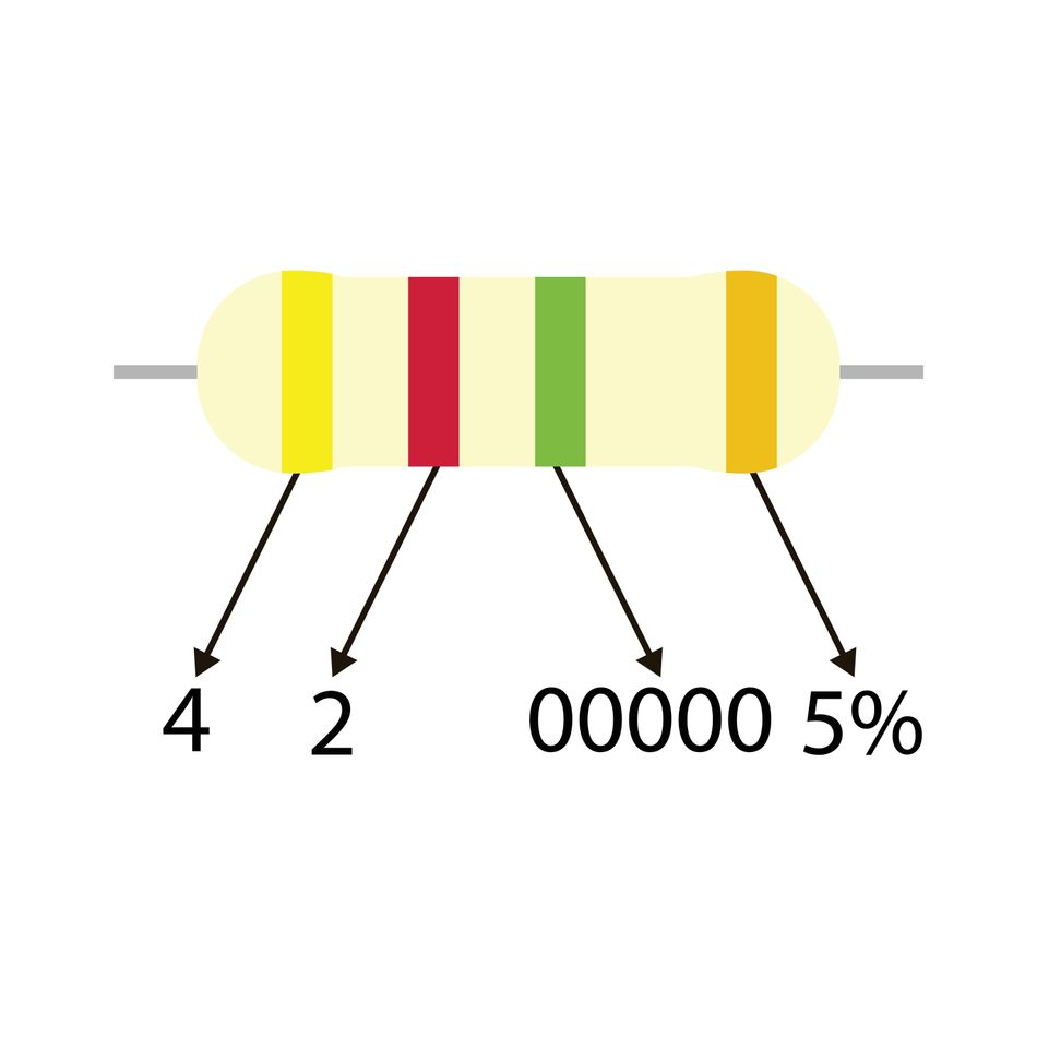
This code reads as “42 × 100000 Ω, ±5%”, which is 4200000 Ω ±5%, i.e. 4.2 MΩ ±5%. If there were no tolerance band (older 3-band code), the tolerance would be assumed to be ±20% by default.
5-Band Resistors
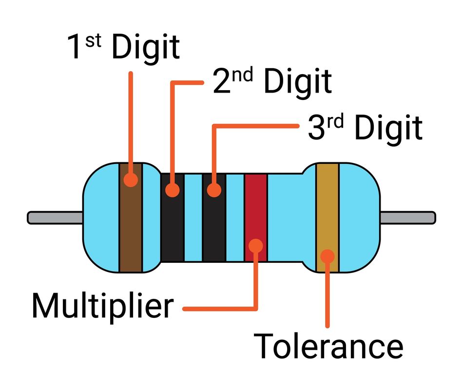
Precision resistors (±1% or ±2%) often use a 5-band code to include a third significant digit for more accuracy. The pattern is:
1st digit – 2nd digit – 3rd digit – multiplier – tolerance.
For instance, a resistor marked Brown – Black – Black – Red – Gold would be decoded as:
Brown = 1 (First Digit)
Black = 0 (Second Digit)
Black = 0 (Third Digit)
Red = 100 (Multiplier i.e. 10^2)
Gold = 5% tolerance
The code will read “100 x 100 Ω ±5%” i.e. 10 kΩ ±5%
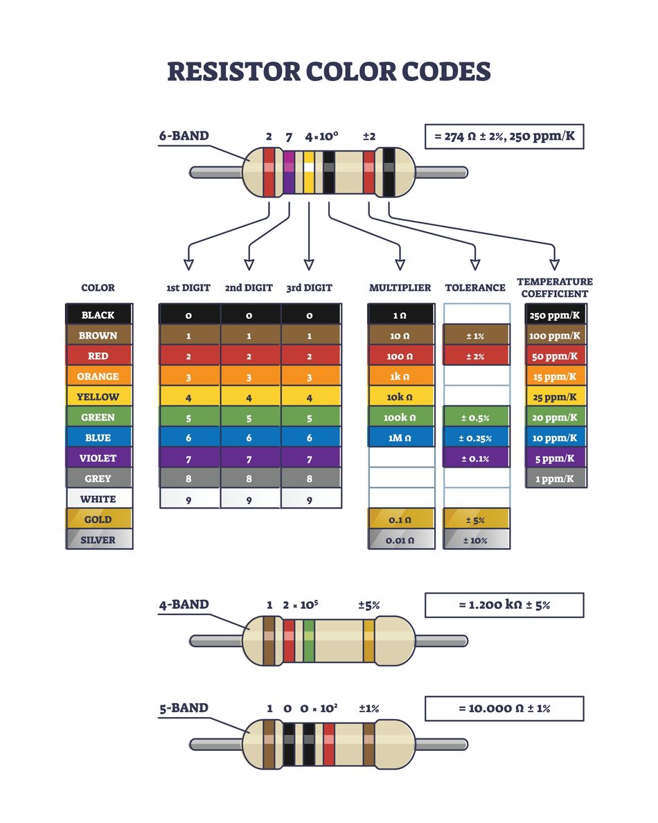
6-Band Resistors
Some resistors, especially high-precision ones or special types, have a 6th band. This sixth band typically represents the temperature coefficient (TC) of the resistor in ppm/K (parts per million per Kelvin). The first five bands are read like a 5-band resistor (three digits, multiplier, tolerance), and the 6th band color gives the tempco.
Common temperature coefficient colors are:
Color | Temperature Coefficient (ppm/K) |
Brown | 100 |
Red | 50 |
Orange | 15 |
Yellow | 25 |
Blue | 10 |
Violet | 5 |
For example, the 6-band resistor shown in the figure below has a 274 Ω resistance at 2% tolerance and a temperature coefficient of 250 ppm/K.

In summary, the color coding system condenses a lot of information onto a tiny component. A resistor color code chart is often printed on lab benches or inside electronics textbooks for quick reference, mapping each color to its digit, multiplier, and tolerance value.
Practical Examples of Resistor Selection
Understanding theory is great, but how do we use these resistor charts and values in real design work? Let’s go through a few common scenarios that hardware engineers and students encounter and see how resistor values are chosen in practice using standard values.
1. Pull-Up Resistors (Digital Inputs)
Pull-up resistors are used to ensure a digital input or open-collector/drain node defaults to a logical “1” (high voltage) when no active drive is present. The value of a pull-up needs to be high enough that it doesn’t source too much current when the input is pulled low but low enough that it can reliably pull the line high without interference or noise.
Common practice is to use a value around 10 kΩ for many general-purpose pull-ups. A 10 kΩ pull-up on a 5 V logic line draws only 0.5 mA when pulled low (5 V/10 kΩ = 0.5 mA) and consumes negligible power when the input is high, yet it provides a defined logic level and some noise immunity. Indeed, 10 kΩ is often recommended as a good default because it balances leakage currents and noise stability in typical 5 V or 3.3 V systems.
In special cases like I²C buses, lower pull-ups (~4.7 kΩ or even 2.2 kΩ) are used to achieve faster rise times because the bus capacitance needs a stronger pull-up; this comes at the cost of higher current. Conversely, internal microcontroller pull-ups might be around 20–50 kΩ to save power when speed isn’t critical.For most cases, 4.7 kΩ to 10 kΩ is a typical range for pull-ups in resistor value charts provided by application notes.
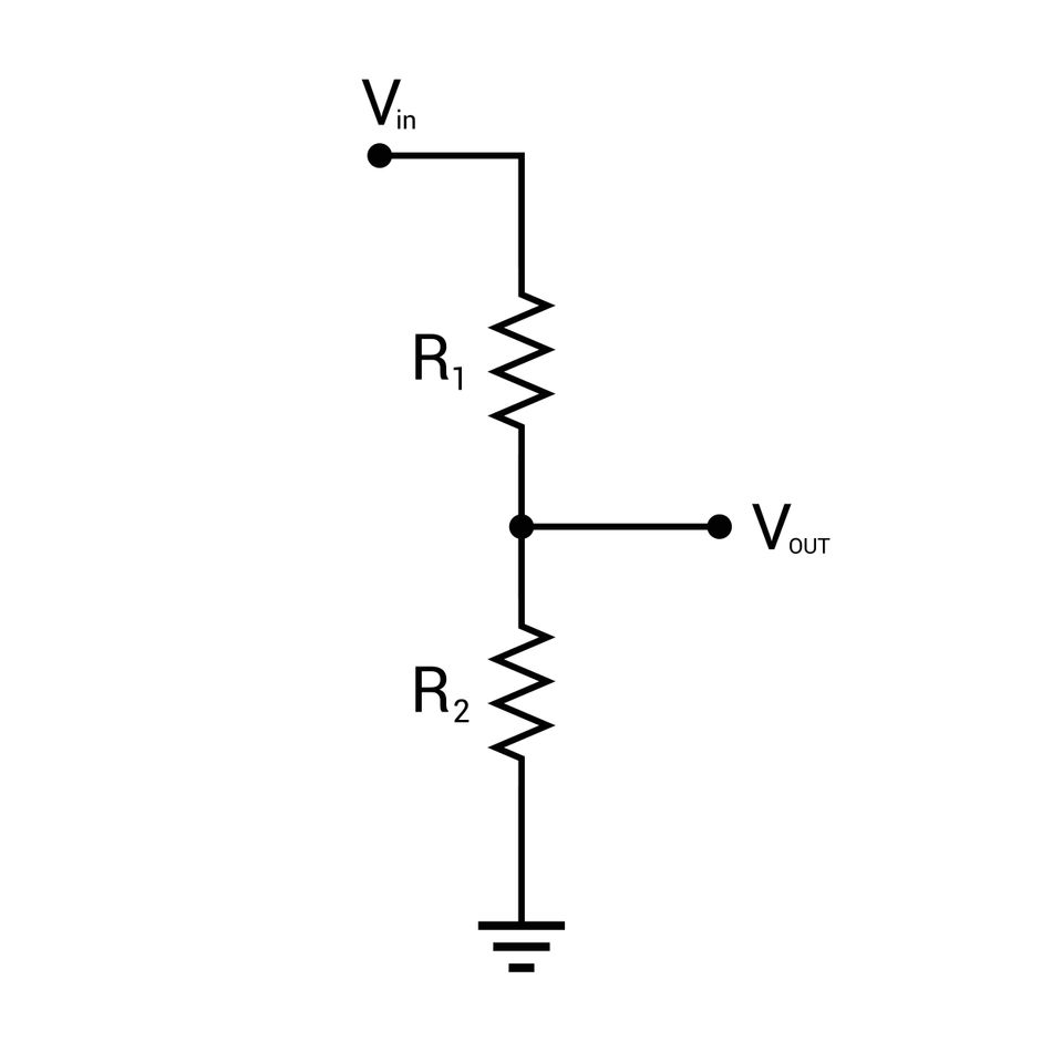
2. Voltage Dividers
A voltage divider uses two resistors to produce an output voltage that is a fraction of the input voltage. The classic formula is:
V_out = V_in × (R2 / (R1 + R2)),
where V_out is across R2. When designing a divider, you often start with the ratio needed and then choose actual resistor values from the standard E-series.
For example, imagine you have a 12 V source and need approximately 5 V for an ADC input. The ratio required is 5/12 ≈ 0.4167. This could be achieved by many pairs of R1 and R2; a convenient approach is to pick one resistor and solve for the other. Say we choose R2 = 4.7 kΩ (a common value). Using the formula: 0.4167 = R2/(R1+R2), solve for R1 ≈ 6.6 kΩ. The nearest standard values are 6.8 kΩ or 6.2 kΩ (from the E12 series). Using R1 = 6.8 kΩ and R2 = 4.7 kΩ, the divider output will be: 12 V × (4.7/(6.8+4.7)) = ~4.94 V, which is very close to 5 V – well within tolerance for most ADCs. Both 6.8k and 4.7k are in the resistor chart (E12 series for 5% parts), making them easy to obtain. If we needed a more exact 5.00 V, we might look at E96 (1%) values like 6.65 kΩ, but generally using E12 values gets us close given typical tolerances.
Key consideration when selecting divider resistors are the current through the divider (too low a resistance wastes power; too high a resistance might make the output susceptible to noise or input bias currents). Often, a pair of resistors in the tens of thousands of ohms (e.g., 22 kΩ and 33 kΩ for a half divider) is a good compromise.
3. LED Current Limiting Resistor
When hooking up an LED to a power source, a resistor is used in series to limit the current to a safe value (since LEDs drop a fixed voltage and would otherwise draw too much current).
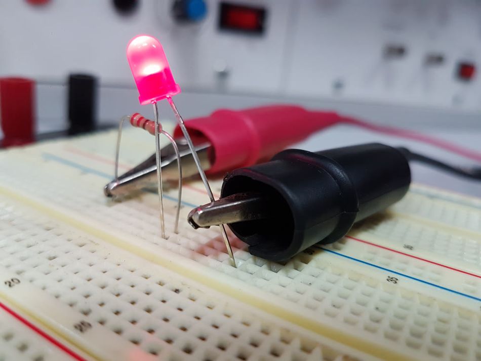
The resistor value is computed from Ohm’s law: R = (V_source – V_LED) / I_LED. For example, with a 5 V supply and a red LED (~2.0 V forward drop) desired at I_LED = 10 mA (0.01 A), R = (5 V – 2 V) / 0.01 A = 300 Ω. Looking at a standard resistor chart (E12 series for 5% resistors), 300 Ω is not a common value – you’ll find 270 Ω, 300 Ω (not in E12), 330 Ω… Actually, 300 Ω is an E96 1% value, but not an E12 value. The nearest 5% values are 270 Ω or 330 Ω. In this case, it’s safer to go high: choose 330 Ω (which will give about 9 mA, a slightly dimmer LED but longer life). 330 Ω ±5% (Orange-Orange-Brown-Gold) is a very common resistor value found in charts. If you needed the LED brighter and have 5% resistors, you might use 270 Ω for ~11 mA (if the LED can handle it). Typically, designers will pick the closest higher standard value to stay conservative with current.
For another example, consider a 3.3 V microcontroller pin driving a blue LED (forward drop ~3.0 V). Desired current 5 mA. R = (3.3–3.0)/0.005 = 60 Ω. E12 series has 56 Ω or 68 Ω. Going with 68 Ω (Blue-Gray-Black-Gold) limits current to ~4.4 mA, which is fine. These values (330 Ω, 68 Ω, etc.) all come straight from the standard resistor value chart, ensuring you can readily find them.
Conclusion
Understanding resistor values is fundamental to electronic design. This article provided a comprehensive guide to the resistor value system, explaining how resistors are quantified in ohms and the common prefixes used for larger values. It also detailed the E-series standard values, a crucial system that manufacturers follow, simplifying component selection for engineers. Furthermore, the article thoroughly explained the resistor color code for 4-band, 5-band, and 6-band resistors, demonstrating how to interpret the color chart for digits and multipliers.
By utilizing these standardized systems, engineers can reliably select readily available components that meet necessary tolerance levels. The principles and charts discussed are essential tools for various tasks, from selecting pull-up resistors to designing voltage dividers. Keeping a resistor chart readily accessible can significantly improve efficiency and accuracy in electronic work. Ultimately, a strong understanding of resistor values, tolerances, and color codes empowers individuals to confidently specify the correct resistor for any electronic application, making them well-prepared for both design and troubleshooting.
FAQs
1. What is a “resistor chart” and how do I use it?
A resistor chart is a reference that typically includes standard resistor values (like the E-series lists) and/or the resistor color code key. Engineers use these charts to quickly find the nearest standard value to a calculated resistance or to decode the value from color bands on a resistor. For example, if you calculate you need ~47 kΩ, a quick glance at the E12 resistor chart shows that 47 kΩ is indeed a standard value. Or if you have a resistor with stripes Brown-Black-Orange-Gold, using the color chart you’d decode that as 10×10^3 = 10 kΩ ±5%.
2. Why do resistor values come in odd numbers like 4.7, 6.8, 33, etc., instead of round numbers?
These values are part of the standardized E-series. The sequence might look odd, but it’s logarithmically spaced. The idea is that each value is a certain percentage apart to accommodate the tolerance. For 5% resistors (E24 series), for instance, 4.7 Ω and 5.1 Ω are about 5% apart. Using standard ratios ensures any value within tolerance overlaps with an adjacent preferred value’s range . This avoids “gaps” in coverage. So those “odd” numbers like 4.7 Ω, 6.8 Ω, 33 Ω, 47 kΩ, etc., are chosen so that with tolerance, they cover a continuous range of resistances. It also simplifies manufacturing and inventory by limiting to a set of preferred values.
3. How do I read a 5-band or 6-band resistor color code?
In a 5-band code, the first three colored bands are the first three digits of the resistance value, the fourth band is the multiplier, and the fifth band is the tolerance. For example, Yellow-Violet-Black-Brown-Brown: Yellow(4), Violet(7), Black(0) gives “470” as the digits, Brown (multiplier 10^1) means ×10, so that’s 470×10 = 4700 Ω, and the last Brown is ±1% tolerance, so it’s a 4.7 kΩ 1% resistor. A 6-band code adds a sixth stripe for temperature coefficient (in ppm/°C). For instance, if the sixth band is Red, it means 50 ppm/°C – the resistance changes by at most 0.005% per °C. If you have trouble, refer to a resistor color chart which lists the meaning of each color for each band position.
4. What’s the difference between 4-band and 5-band resistors in practice?
It usually comes down to tolerance (precision). 4-band resistors are typically ±5% or ±10% tolerance (sometimes 20% in older carbon resistors). They use two-digit codes, which is sufficient given the wider tolerance. 5-band resistors are typically ±1% or ±2% precision metal film resistors. They use three digits for greater resolution, reflecting the tighter tolerance. In a circuit, they both do the same job (provide resistance), but 5-band parts will be closer to their stated value. Also, many 1% resistors have a blue body with 5 (or 6) bands, whereas 5% ones often have a beige body with 4 bands – this isn’t a strict rule, but a common visual cue.
5. How do I choose the right resistor value for my application?
First, determine what function the resistor serves (current limiting, voltage dividing, pull-up, etc.) and use the relevant electrical formulas (Ohm’s law, divider equation, etc.) to calculate a target resistance. Next, consider the context: does it need to be a common value? What tolerance can you tolerate? Then consult the standard resistor chart to find the nearest preferred value that meets your needs. For example, if calculation says 315 Ω, the E12/E24 chart shows 300 Ω or 330 Ω; you might pick 330 Ω to be safe on current. Also factor in power rating (a resistor chart typically doesn’t list power, but standard through-hole resistors are 1/4 W or 1/2 W – ensure the chosen resistor can dissipate the power in your circuit). In summary, pick the closest standard value, choose an appropriate tolerance class (e.g., don’t use a 20% part for precision sensing), and ensure the power rating is sufficient. Using a resistor chart of values and color codes will help in making a quick and informed decision.