How to Calculate Power: A Comprehensive Guide for Engineers and Students
Understanding how to calculate power in electrical, mechanical and digital systems is essential for designing energy efficient circuits and machines. This guide combines theory, formulas and practical measurement methods to equip digital design engineers, hardware engineers and electronics

22 Oct, 2025. 14 minutes read

Key Takeaways
In every system, electrical, mechanical or digital, the measure of power is the rate of energy transfer, also known as the rate of work, done. Hence, the general definition of power is Work/time (W/t).
In DC circuits, power is measure using P = VI or P =I2R, while AC circuits need power factor and can differentiate between reactive, real, and apparent power. Mechanical systems use P = F × v (for translational motion) and P = τ × ω for (rotational motion). In CMOS logic dynamic and static power models such as P = = α × C_L × V² × f are used.
Power is usually measured using indirect methods, i.e., using voltage and current readings for electrical circuits. In digital circuits, instrumentation and simulations help in estimating switching and leakage power.
Designers choose various techniques like voltage scaling, efficient load matching, and clock gating, based on the mechanical speeds, voltage, load capacitance, switching frequencies, etc.
Introduction
With the continuous evolution and expansion of electronics and implementation of computing across industries, accurate power calculation becomes a critical factor. Whether it’s high high‑speed digital logic, or motor drives and renewable‑energy converters, it is crucial for engineers to ensure their designs deliver the required performance without wasting energy or generating excessive heat. From mechanical to electrical and digital domains, power calculation touches multiple disciplines:
Digital design engineers must estimate static and dynamic power to meet thermal budgets and battery life requirements.
Hardware engineers build power converters, motors and IoT devices and must understand AC and DC power relationships and measurement techniques.
The fundamental equations of power calculation are pivotal for electronics engineering students to help them solve circuit problems and later apply low‑power design strategies in the workplace.
In this article, readers will learn a holistic tutorial on how to calculate power, organized by domain. Initially, we will discuss the fundamental definitions and then cover:
DC and AC circuits
Mechanical systems
Power measurement techniques
Digital CMOS power models.
Find out the important formulas with clear explanations and practical examples. We will also cover concepts like the power triangle and see design tips for minimizing power consumption.
Suggested Reading: Types of Circuits: A Comprehensive Guide for Engineering Professionals
Fundamentals of Power
What is Power?
The rate of energy transfer or conversion is called Power. Mathematically, power P equals the work W done or energy E, expended per unit time:

What is Energy?
Energy has various forms. It can be mechanical (kinetic or potential), electrical or thermal. When power is multiplied by time, the result is energy:

Generally, energy is expressed in joules (J), kilowatt‑hours (kWh) or electron‑volts (eV) depending on context.
Instantaneous vs. Average Power
Instantaneous power is power taken at any instant, assuming that the change in time t tends to 0. It is the product of instantaneous voltage and current:

In a DC circuit with constant voltage and current, instantaneous power is equal to average power.
Average power is the time‑average of instantaneous power over a period T:

To calculate average power, AC circuits use RMS values (root‑mean‑square) of voltage and current, etc.
Units of Power
The SI unit of power is the watt (W). 1 W = 1 joule per second.
Larger units power generation systems, generators, inverters, etc, often use kilowatts (kW) and megawatts (MW);
In smaller devices like microcontroller boards, phone chargers, smart watches, power may be rated in milliwatts (mW) or microwatts (µW).
Mechanical systems typically sometimes use horsepower (1 hp ≈ 746 W).

Calculating Power in DC Circuits
DC circuits have a simple method to calculate electrical power. A constant voltage and current provide the simplest context for how to calculate power. Power calculation in DC circuits is derived from the basic relationships in Ohm’s law (V = I × R) and the definition of power.
Core Formulas for DC Power
Formula | Description | Notes |
P = V × I | Power is the product of voltage V and current I. | Fundamental definition used when measuring both quantities directly. |
P = I² × R | Power equals current squared times resistance R. | Derived by substituting V = I × R into P = V × I. |
P = V² / R | Power equals the square of voltage divided by resistance. | Derived by substituting I = V/R into P = V × I. |
These formulas are mainly for resistive DC loads and use instantaneous values. In case of variable loads (e.g., pulses), power is usually integrated over time for average values.
Practical Measurement with a Multimeter
Power is a derived quantity, so there is no direct way to measure it. When it comes to physical measurement of power, engineers need to measure voltage and current and compute power. Here is a typical power measurement sequence.
Measure voltage: Connect the multimeter in parallel across the load. Set the meter to an appropriate DC voltage range.
Measure current: break the circuit and insert the meter in series. Many meters include different current ranges—choose one above the expected current to avoid blowing a fuse.
Calculate power: multiply the measured voltage and current (P = V × I). For example, a 110 V DC supply delivering 5A to a heating element consumes 110 × 5 = 550 W.

Suggested Reading: Parallel vs Series Circuits: Differences, Theory, and Practical Applications
Example 1 – DC Power Calculation
Suppose you want to measure how much power your microcontroller board draws. Assuming you have a 5.0 V USB supply, you can measure the power as follows:
Use a shunt resistor or USB current meter. You may find I = 0.25 A and V = 5.0 V.
Compute: P = V × I = 5 × 0.25 = 1.25 W.
If your board is powered by a battery, you can use the calculated value to estimate the battery life. For instance, assuming that your board runs on a 10 Wh battery, the theoretical runtime is 10/1.25 ≈ 8 h (neglecting efficiency losses).
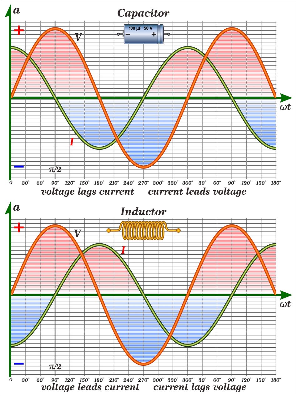
Calculating Power in AC Circuits
AC power calculation is more complex than DC power as alternating current introduces phase differences between voltage and current. It also introduces the concepts of real power (P), reactive power (Q) and apparent power (S), also known as the power triangle.
RMS Values and Power Factor
- RMS voltage Vrms and RMS current Irms are used as equivalent DC values that produce the same heating effect. For a sinusoid:
- Power factor (pf) is the cosine of the phase angle θ between voltage and current: Power factor ranges from 0 to 1 and shows how effectively the current contributes to real work. In power-efficient systems, the power factor is very close to 1.


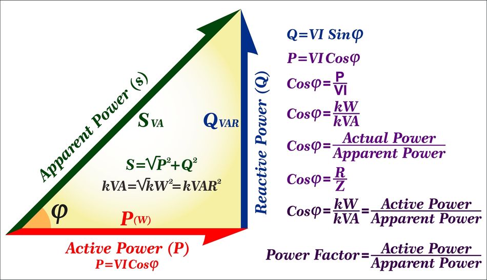
Real, Reactive and Apparent Power
Real power is also called active or true power. It is the rate at which energy is consumed or delivered to perform useful work. It is given by:

It is a direct measure of heating or mechanical work and is measured in watts (W).
Reactive power shows the energy that oscillates between the source and reactive components (inductors and capacitors). It is represented by:

Reactive power does not perform the usual work. Instead, it causes the current to flow in the circuit. It is measured in volt‑ampere reactive (var).
Apparent power is the product of RMS voltage and current, irrespective of phase:

It shows the total power delivered by the source, and is measured in volt‑amperes (VA).
The three power quantities are related to each other through the power triangle. In this triangle, S is the hypotenuse, P the adjacent side and Q the opposite side. The relationships are:

The following figure shows the power triangle and their calculation formulae.
AC Power Formulas for Single‑Phase and Three‑Phase Systems
Single‑Phase AC:
In single-phase AC systems, the power calculation formula is the same as that for average real power. In purely resistive loads, there is no phase difference, so effectively, real power is the same as DC power P = VI. When inductive or capacitive loads are added, it lowers the power factor.
Example: A 230 Vrms heater draws 10 A with power factor 0.95. Real power = 230 × 10 × 0.95 = 2.185 kW.
Three‑Phase AC:
Balanced three‑phase systems have two common forms of connection:
Line to Line (VLL)
Line‑to‑neutral (VLN)
Real power is given by:

where I is the line current. The factor √3 arises from the 120° phase displacement between phases. For reactive and apparent power, the formula coefficients are the same but they include sin θ.
Measuring AC Power
Since AC power depends on voltage, current and phase angle, instruments like power analyzers or wattmeter are used. These devices sample voltage and current waveforms, compute instantaneous power, average it over a cycle and display real, reactive and apparent power.
Moreover, digital oscilloscopes with math functions can perform similar computations when phase information is available.
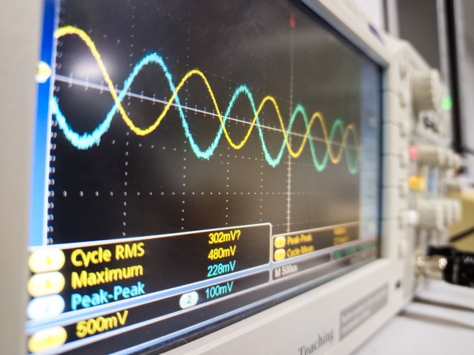
In field work, multimeters can approximate AC power for near‑unity power factor loads by measuring RMS voltage and current and assuming cos θ ≈ 1. For non‑resistive loads, specialized tools are recommended.
Recommended Reading: Understanding Multimeter Symbols: A Comprehensive Guide for Engineers
Mechanical Power: Translational and Rotational Motion
Power is a universal concept, so it applies to mechanical systems as well. In mechanical systems, power calculation for translational and rotational motions have analogous formulas.
Translational Power
Translational power is observed when a constant force F moves an object at constant velocity v. The delivered power is the dot product of force and velocity:

Here P is in watts, F in newtons and v in metres per second. This relationship states that to deliver the same power, a higher speed requires less force and vice versa.
Example: A linear actuator pushes with 200 N force at 0.15 m/s. The mechanical power = 200 × 0.15 = 30 W.

Rotational Power
For rotating machinery, the analog of force is torque τ and the analog of velocity is angular velocity ω (radians per second). The power delivered by a torque is calculated by the following formula:

This can also be expressed using rotational speed n in revolutions per second (rps) or revolutions per minute (rpm):

Example: A motor produces 1.2 N·m torque at 1500 rpm. The power = (1.2 × 2π × 1500) / 60 ≈ 188 W.
Comparing Electrical and Mechanical Power
In electromechanical systems like motors and generators, electrical power inputs/outputs are converted to mechanical power and vice versa. The power efficiency (η) is calculated as:
η = (Pout / Pin) × 100 %
In motor datasheets, the rated power and efficiency is always listed. Therefore, understanding the mechanical formulas helps verify these values and size power supplies appropriately.
Suggested Reading: How Does a DC Motor Work? Unveiling the Power Behind Electric Motion
Power Calculation in Digital CMOS Circuits
Power consumption is a major concern in digital circuits as they are heavily focused on shrinking transistor dimensions and increased integration. Unlike analog or mechanical systems, digital designs in CMOS logic exhibit unique power dissipation mechanisms.
Static Power
Static power is also called leakage power, and it is consumed when a circuit is idle. It results due to subthreshold leakage, gate‑oxide tunnelling and reverse‑bias currents. It is proportional to supply voltage and leakage current:

The total dynamic power is the sum of switching and short‑circuit components.
To cater static power, reducing supply voltage or using high‑threshold transistors are commonly employed. For modern processes, leakage current increases exponentially with temperature, so thermal management and power gating are important.
Dynamic Power
Dynamic power dominates when the circuit is active or switching. In CMOS, two mechanisms contribute:
Switching (charging/discharging) power: Every time a CMOS node transitions from 0 to 1, the load capacitance CL is charged to the supply voltage; on a 1 to 0 transition it discharges. The average switching power is given as:

The dynamic power is given as:

Short‑circuit power: During switching, both PMOS and NMOS transistors may be partially ON simultaneously. It creates a short‑circuit path from supply to ground. The short‑circuit power depends on transition time (Tsc) and peak current Ipeak:

Impact of Voltage, Capacitance and Frequency
The dynamic power equation shows that power scales quadratically with supply voltage. Reducing VDD by 30 % can nearly halve dynamic power. Similarly, decreasing load capacitance and switching activity reduces power. Frequency scaling is also effective because power is proportional to frequency.
Low‑Power Design Techniques
Modern digital designs deploy multiple strategies to reduce power:
Clock gating disables clock signals to idle blocks, reducing dynamic switching activity.
Power gating disconnects the supply from blocks not in use, lowering static leakage.
Dynamic voltage and frequency scaling (DVFS) adjusts supply voltage and clock frequency based on performance needs; because P ∝ V² × f, modest reductions yield large savings.
Multi‑threshold CMOS uses high‑threshold devices for non‑critical paths to minimize leakage and low‑threshold devices for speed‑critical paths.
Reducing switching activity via bus encoding or glitch filtering reduces the effective α in the dynamic power formula.
While these techniques are beyond the scope of simple calculations, understanding the power equations helps designers justify such architectural decisions.
Measuring Digital Power
Estimating dynamic power in large ASICs or FPGAs often requires simulation tools that compute switching activity and capacitances. Post‑silicon, engineers may measure supply current using an ammeter or sense resistor and compute average power (P = V × I).
For dynamic profiling, oscilloscopes with current probes capture transient waveforms. Shunt‑resistor methods, described below, provide an inexpensive way to monitor current waveforms.
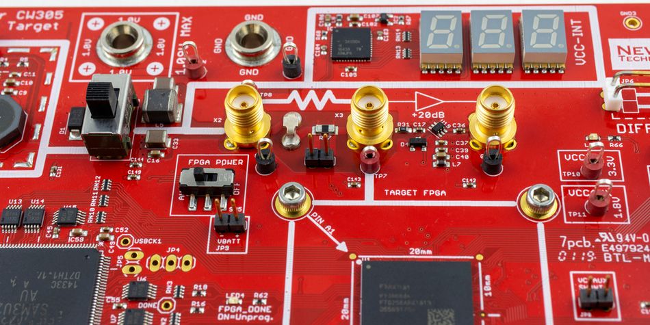
Measuring Power with Oscilloscopes and Shunt Resistors
Shunt Resistor Current Measurement
Oscilloscopes measure voltage by default; but to measure current, engineers often insert a shunt resistor of known resistance R in series with the load. The voltage drop across the shunt is proportional to current according to Ohm’s law (I = V/R). A shunt resistor should have low resistance to minimize voltage drop and low inductance to avoid distorting high‑frequency signals. It should also have a low temperature coefficient to maintain accuracy.
Steps:
Select a precision shunt resistor. Values between 0.001 Ω and 1 Ω are common, depending on expected current.
Insert the shunt in series with the device under test. Ensure the shunt is rated for the maximum current and power dissipation.
Connect the oscilloscope or differential probe across the shunt to measure the voltage drop. Ensure ground reference is correct to avoid short circuits.
Compute current as I(t) = Vshunt(t)/R.
Multiply the instantaneous current waveform by the simultaneously measured voltage waveform to obtain instantaneous power. Many oscilloscopes include math functions for this purpose.
This method is especially useful for switching power supplies and digital loads where current varies rapidly.
While choosing the Shunt resistor, ensure the following:
Too high value increases voltage drop and power loss; too low may reduce measurement accuracy. Choose the smallest value that yields measurable voltage without significantly disturbing the circuit.
The shunt must dissipate I² × R watts. Ensure it has adequate thermal margin.
Frequency response: For high‑frequency currents, resistors with minimal parasitic inductance (e.g., surface‑mount or four‑terminal shunts) should be used.
Using Current Probes
Alternatively, current probes (clamp‑on or Hall‑effect sensors) can sense current without inserting a resistor. They offer convenience and high bandwidth but may be expensive. For low‑current microcontroller power rail measurements, specialized probes can isolate common‑mode voltages.
Suggested Reading: Tips: How to Select an Oscilloscope Before you Buy
Application Example – Power Analysis of a DC Motor Controller
Suppose you are designing a battery‑powered robot that drives a DC motor and includes a microcontroller. Your goal is to compute both electrical and mechanical power and verify efficiency.
Here is the possible data that you have:
Battery voltage: 12 V
Motor stall torque: 1.0 N·m
Operating torque at desired speed: 0.4 N·m
Rotational speed: 3000 rpm
Microcontroller current: 150 mA at 5 V (using a regulator)
Motor controller efficiency: 90 %
The following steps will help you compute the power:
Calculate the mechanical power of the motor
Calculate the electrical powered delivered to the motor
Calculate the battery current for the motor
Calculate microcontroller power
Estimate the total system power
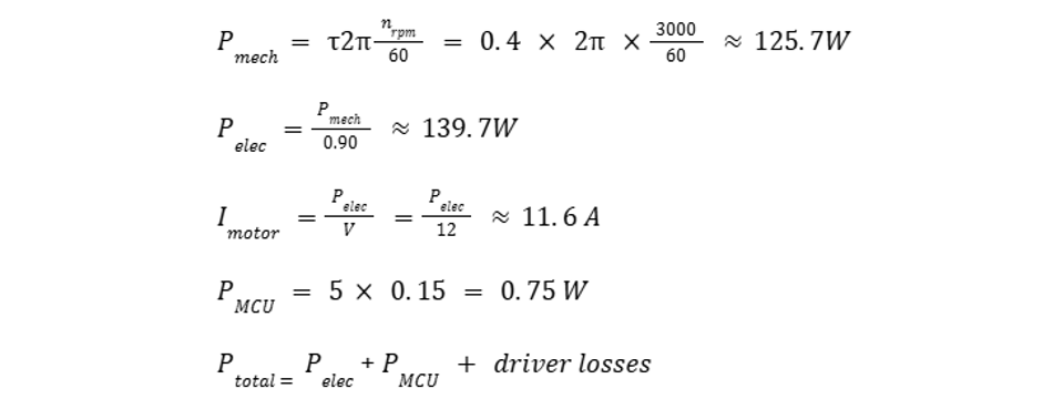
It demonstrates how combining mechanical and electrical power calculations yields overall energy requirements.
Moreover, engineers can measure the actual current with a shunt resistor and oscilloscope to validate the above estimates, and then size the battery capacity accordingly.
Recommended Reading: Motion Control in Robotics: 4 Types of Motors for Industrial Robots
Design Considerations for Minimizing Power Consumption
Power efficiency a critical factor which reduces operational costs and manages thermal constraints and eventually, extends battery life. Here are some practices help engineers design low‑power systems:
Reduce supply voltage and capacitance: Since dynamic power in CMOS scales with V² and total capacitance C, lowering supply voltage and minimizing fanout reduces power dramatically. It’s also a good practice to use careful cell sizing and layout to cut unnecessary capacitance.
Optimize switching frequency: Slowing the clock or switching less frequently lowers dynamic power. So, it’s best to use asynchronous or event‑driven architectures when possible.
Implement power gating and clock gating: When unfunctional, it’s important to turn off inactive blocks to reduce both static and dynamic power. Use retention registers to preserve state during sleep modes.
Manage mechanical load: For motors, match load torque to the optimum efficiency point. Over‑driving increases current draw and wastes power as heat.
Improve power factor: In AC systems, add capacitors or active PFC circuits reduces reactive power and lowers current, improving efficiency and reducing conductor losses.
Use high‑efficiency power converters: Switching regulators (buck/boost) deliver higher efficiency than linear regulators, minimizing power lost in voltage conversion.
Conclusion
Calculating power accurately is a basic skill for modern engineers and students. Whether you are dealing with DC circuits, AC systems, mechanical drives or digital logic, understanding these underlying formulas and measurement techniques enables designers to size power supplies, predict thermal performance and optimize efficiency.
In this article, we saw:
How to compute power in resistive circuits using P = V × I and its variants;
How to analyze AC systems using RMS values, power factor and the power triangle;
How mechanical power arises from force–velocity and torque–speed relationships;
How CMOS power combines static and dynamic components with strong dependence on voltage and capacitance.
We also discussed the practical measurement methods, and the strategies to reduce power consumption. By mastering these principles, engineers can build robust, energy‑efficient systems that meet today’s demands.
FAQs
1. Why is power not measured directly but calculated from voltage and current?
Most instruments cannot directly sense power as it is an instantaneous product of voltage and current. Instead, devices measure voltage and current separately and multiply the values to compute power. This approach also allows separation of real and reactive components in AC systems by considering phase angles.
2. What is the difference between apparent, real and reactive power?
In AC circuits, apparent power S is the power supplied to the circuit. Real power P is the portion that performs useful work, while Reactive power Q is due to energy stored and released by inductors and capacitors
3. How does lowering supply voltage reduce power in digital circuits?
Dynamic power in CMOS circuits is proportional to the square of the supply voltage: P ∝ V². Reducing the supply voltage results in yields a quadratic reduction in power. However, lowering voltage also reduces switching speed, so designers use techniques like dynamic voltage scaling to balance performance and power.
4. Can I compute mechanical power using electrical measurements?
Yes. In motors, electrical power input (V × I minus losses) equals mechanical power output (τ × ω) times efficiency. Therefore, by measuring current and voltage and referencing motor efficiency, you can estimate torque and speed, or vice versa.
5. What is a shunt resistor and why is it used for current measurement?
A shunt resistor is a precision resistor placed in series with a circuit to produce a small, measurable voltage drop proportional to current. Oscilloscopes measure this voltage and compute current without interrupting the circuit. Shunts must have low resistance, low inductance and sufficient power rating.
6. How do I calculate power in a three‑phase AC system?
For balanced three‑phase loads, you can calculate the real power by using the line to neutral voltage or line to line voltage, phase current, and the load power factor. These values are then plugged into the formula for calculating power.
7. What role does power factor play in efficiency?
A low power factor means more current is required to deliver the same real power. It increases conductor losses and potentially overloads overloading equipment. Correcting power factor (e.g., using capacitors) reduces reactive power, lowers current and improves overall system efficiency.
References
"CMOS Power Calculation," resources.pcb.cadence.com, https://resources.pcb.cadence.com/blog/2023-cmos-power-calculation.
"Power in Digital Circuits," schaumont.dyn.wpi.edu, https://schaumont.dyn.wpi.edu/ece574f24/09power.html.
"How to Measure Power Using a Multimeter," electricaltechnology.org, https://www.electricaltechnology.org/2021/06/measure-power-using-multimeter.html.
"Relationship: P = EIcosθ Watts," engineering.louisville.edu, https://engineering.louisville.edu/raise/EE220/L12.html.
"Force and Velocity to Power Calculator," sensorsone.com, https://www.sensorsone.com/force-and-velocity-to-power-calculator.
"Angular Velocity, Acceleration, Power, Torque," engineeringtoolbox.com, https://www.engineeringtoolbox.com/angular-velocity-acceleration-power-torque-d_1397.html.
"Relation Between Torque and Power," byjus.com, https://byjus.com/physics/relation-between-torque-and-power.
"Measuring Current Using Shunt Resistors," tek.com, https://www.tek.com/en/blog/measuring-current-using-shunt-resistors.
in this article
1. Key Takeaways2. Introduction3. Fundamentals of Power4. Calculating Power in DC Circuits5. Calculating Power in AC Circuits6. Mechanical Power: Translational and Rotational Motion7. Power Calculation in Digital CMOS Circuits8. Measuring Power with Oscilloscopes and Shunt Resistors9. Design Considerations for Minimizing Power Consumption10. Conclusion11. References