Understanding Multimeter Symbols: A Comprehensive Guide for Engineers
Knowing what each multimeter symbol means is essential for digital design engineers, hardware engineers, and electronics students. This guide explains the theory behind common symbols, demonstrates their practical application, and highlights key safety considerations.

12 Aug, 2025. 13 minutes read
Key Takeaways
Recognize core measurement symbols for AC/DC voltage, current, and resistance (Ω\OmegaΩ). Engineers must select the correct range and jacks for precise readings.
Understand advanced functions like low‑impedance Auto‑V/LoZ, low‑pass filters, Min‑Max recording, and smoothing. These modes enhance measurement accuracy but require proper use.
Safety ratings and jacks matter. Knowing CAT ratings, IP codes, and the purpose of each jack prevents accidents when measuring high‑energy circuits.
Practical techniques improve reliability. Pre‑inspection, correct lead placement, power isolation, and verifying fuse integrity ensure safe and repeatable measurements.Continuous learning enhances troubleshooting. Combining symbol knowledge with measurement strategies (continuity, diode test, capacitance) helps engineers diagnose complex systems faster.
Introduction
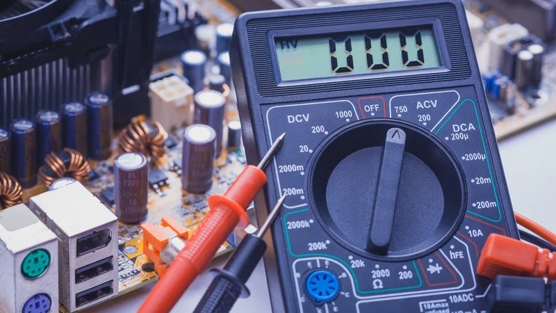
Digital multimeters (DMMs) are the workhorses of modern electronics labs. They measure voltage, current, resistance, capacitance, and more, enabling engineers to validate designs, debug hardware, and ensure product safety. Yet, the rotary dial of a multimeter can appear cryptic: strange glyphs, letters like μ or hFE, and combinations of squiggly and straight lines. Misinterpreting these symbols risks inaccurate readings or, worse, damaging sensitive components.
This article decodes the symbols found on professional digital multimeters and explains their theoretical foundations and practical use. We reference authoritative sources such as Fluke’s user manuals, safety guides, and industry articles to provide a deep technical perspective for design engineers, hardware engineers, and electronics students. Along the way, you will learn how to choose the correct function, understand advanced features like low‑pass filters and dual impedance modes, and apply best practices for safe measurement.
Suggested Reading: Circuit Symbols: A Comprehensive Guide for Electronics Engineers
Fundamentals of Multimeter Operation
A digital multimeter combines three instruments—a voltmeter, ammeter, and ohmmeter—into one handheld device. Modern DMMs are true RMS meters that can measure AC or DC quantities accurately over a wide frequency range. When you turn the rotary switch, you select the measurement function and range. High‑end models, like the Fluke 87V, also include temperature, frequency, and duty‑cycle functions.
Auto‑range vs. Manual Range
Auto‑range multimeters automatically select an appropriate measurement range so you don’t need to guess the magnitude beforehand. However, manual range selection remains useful when you need stable readings or want to avoid range hopping.
On the Fluke 87V, pressing the RANGE button cycles through available ranges; holding it for one second returns to autoranging.
True RMS Measurement
Engineers often encounter non‑sinusoidal waveforms in switching power supplies, motor drives, and digital circuits. True RMS meters calculate the equivalent heating value of complex waveforms, whereas averaging meters may under‑ or over‑represent values. The 80‑series Fluke multimeters provide true RMS measurements for both AC voltage and current.
Decoding Core Multimeter Symbols
The primary measurement symbols denote what quantity the meter will measure. The following table summarises the most common symbols. Remember to connect the black lead to the COM jack and the red lead to the appropriate input jack (V/Ω or A) based on the quantity being measured.
Symbol | Meaning | Typical applications |
V~ | Alternating current (AC) voltage | Measuring mains voltage, transformer outputs |
V⎓ (V with solid and dashed line) | Direct current (DC) voltage | Battery voltage, logic supply rails |
mV, mV~, mV⎓ | Millivolt ranges for sensitive circuits | Low‑level sensor outputs |
A~ | AC current | Mains current in appliances |
A⎓ | DC current | Motor drive current, DC power supplies |
mA, μA | Milliamp and microamp ranges | Analog sensor currents, microcontroller current |
Ω (Ohm) | Resistance | Resistor value verification |
kΩ, MΩ | Kilohm and megaohm ranges | High‑value resistors, insulation testing |
.)) (sideways Wi‑Fi symbol) | Continuity test | Checking closed circuits or shorted traces |
**→ | –** (arrow pointing at line) | Diode test |
[‖] (right‑facing bracket) | Capacitance | Measuring capacitors in microfarads or nanofarads |
Hz | Frequency counter | Oscillator frequency, PWM verification |
% (often combined with Hz) | Duty cycle | Duty cycle of PWM signals |
°C / °F | Temperature measurement | Thermocouple or temperature probe |
Auto‑V / LoZ | Auto‑detect voltage with low impedance | Eliminating ghost voltages |
Low‑pass (K) | Low‑pass filter mode | Filtering high‑frequency components |
Hold / AutoHOLD | Holds current reading until stable | Capturing transient values |
Voltage Measurement Symbols
AC Voltage (V~): The symbol V~ indicates the meter will measure AC voltage. AC is represented by a tilde (~) because the waveform alternates polarity. The Fluke 87V can measure up to 1000 V AC, while many entry‑level meters are limited to 600 V. On many meters, pressing a secondary button toggles a low‑pass filter to improve measurements on noisy AC signals.
DC Voltage (V⎓): The DC voltage symbol shows a solid line over a dotted line. DC remains constant in polarity, such as a battery or regulated supply. Some meters include a dedicated millivolt range (mV⎓) for low‑level signals.
Millivolt (mV): On sensitive circuits, large voltage ranges are impractical; a mV range provides higher resolution. Models like the Fluke 87V have a 600 mV DC range (L switch position L) and a 60 mV AC range accessible via secondary functions.
Current Measurement Symbols
AC Current (A~ ): To measure line current, move the rotary switch to the symbol showing A with a tilde. The red lead plugs into the 10 A or 400 mA jack, depending on the expected current. On the Fluke 87V, pressing the yellow A button toggles between AC and DC in these positions.
DC Current (A⎓): This setting measures current flowing in one direction. Many meters share the same jack as AC but require pressing a button or selecting a secondary range. When measuring current, always start at the highest current jack to avoid blowing fuses.
mA and μA ranges: Microamp and milliamp ranges are invaluable for measuring small currents drawn by operational amplifiers, microcontrollers or leakage paths. A separate mA/μA jack typically supports currents up to 400 mA.
Resistance, Continuity and Diode Symbols
Resistance (Ω): An Ω symbol selects resistance mode. High‑impedance circuits can require kilohm or megaohm ranges. Always disconnect power and discharge capacitors before measuring resistance to avoid damage.
- Continuity (sound‑wave symbol): Continuity testing checks whether two points are electrically connected. The meter emits a beep when the resistance is below a threshold (usually 30–50 Ω). This quick test helps detect solder bridges or broken traces.
Diode Test: The diode symbol tests the forward voltage drop of diodes, LEDs, and transistor junctions. The meter applies a small current and displays the voltage required to forward‑bias the junction (typically 0.6 V for silicon). A reading of “OL” suggests an open or reverse‑biased diode.
Capacitance: Measuring capacitance helps identify capacitor values or detect deterioration. The meter charges the capacitor and computes capacitance based on the time constant. Ensure circuits are de‑energized and discharged before connecting; otherwise, you might damage the meter.
Suggested Reading: Capacitor Polarity: Ensuring Proper Orientation for Optimal Performance
Frequency and Duty Cycle
Modern DMMs include a frequency counter (Hz) and duty‑cycle measurement (%). These functions are useful for verifying oscillators, PWM signals, and clock generators. Some meters allow slope selection (positive or negative) to capture specific transitions; on the Fluke 87V, this is triggered via the Hz% button.
Temperature (°C / °F)
A thermometer symbol indicates a temperature function. The Fluke 87V measures temperature using a type‑K thermocouple. Pressing the °C/°F button toggles between Celsius and Fahrenheit; note that the meter’s thermocouple is rated only to 260 °C even though the meter can display up to 1090 °C.
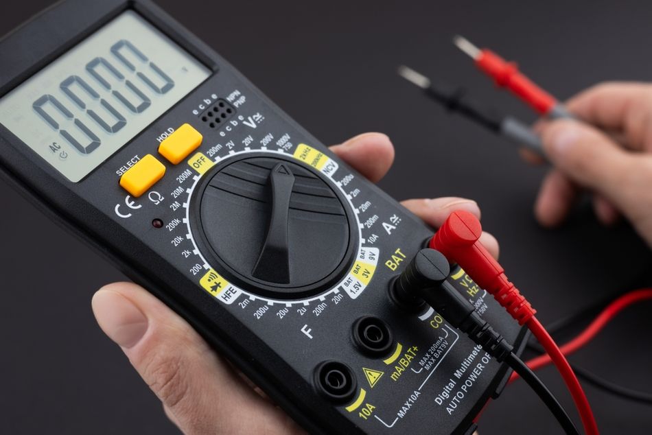
Understanding Input Jacks and Safety Ratings
Misusing the input jacks can damage both the meter and the device under test. The following table summarises typical multimeter input jacks and their functions.
Jack label | Purpose | Current/voltage limit |
A | High‑current input for measuring up to 10 A (often fused) | 10 A continuous, 20 A for 30 s |
mA/μA | Low‑current input for milliamp and microamp ranges | Typically 400 mA; fused |
COM | Common ground reference; connect the black lead here for all measurements | – |
V/Ω/diode/capacitance | Input for voltage, resistance, diode, capacitance, frequency and temperature measurements | Up to the meter’s rated voltage |
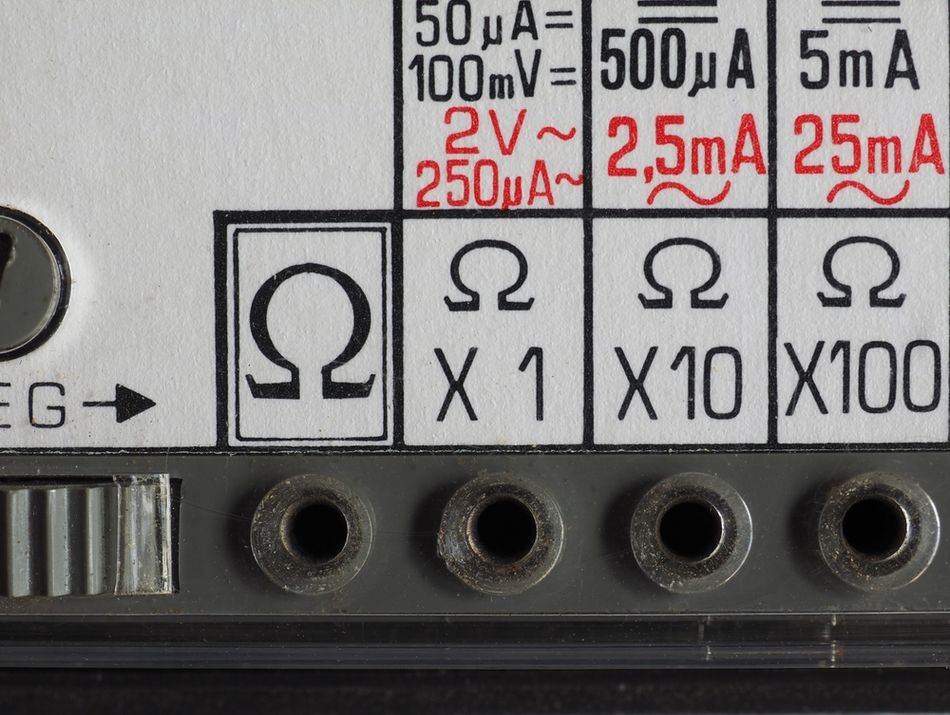
mAVΩ, mAμA, VΩ (older meters) | Combined jacks on 3‑ or 4‑jack designs; check the legend near the jack to understand supported functions |
Over‑voltage Categories (CAT Ratings)
Safety standards classify multimeters by installation category (CAT) and maximum rated voltage. These categories relate to the potential transient energy at the measurement point:
CAT II: Single‑phase receptacle loads and plug‑in equipment (TVs, appliances). Short‑circuit current < 10 kA.
CAT III: Fixed installations like distribution panels, feeders, and short branch circuits. Equipment is designed to handle transients up to 50 kA.
CAT IV: Utility connections and outdoor conductors; highest transient energy (> 50 kA). Use a CAT IV‑rated meter when working at service entrances or utility poles.
Always choose a multimeter with a CAT rating equal to or greater than the highest category in which you expect to work. For example, measuring the output of a three‑phase motor control cabinet requires a CAT III or CAT IV meter. The ratings are printed near the input jacks; verifying them ensures adequate protection from arc flash or overvoltage events.
Ingress Protection (IP) Codes
Multimeters may also carry IP (Ingress Protection) codes that describe resistance to dust and water. For instance, IP54 indicates limited dust ingress and splashing water protection. While not directly related to the symbols on the dial, understanding IP ratings helps engineers choose a meter suited for harsh environments.
Advanced Functions and Their Symbols
High‑end digital multimeters go beyond basic measurement. They integrate features that simplify troubleshooting and improve measurement accuracy. Understanding these advanced symbols ensures you use the features correctly.
Auto‑V/LoZ (Low‑Impedance Mode)
Ghost voltages are stray capacitive couplings that appear on long cables or unused wires. They may read 80–85 % of the actual line voltage when using a high‑impedance meter. Auto‑V/LoZ addresses this problem:
Auto‑V automatically determines whether the signal is AC or DC and selects the appropriate range.
LoZ forces the meter’s input impedance to a low value (around 3 kΩ), bleeding off ghost voltages so that open circuits read near zero.
Use LoZ when you suspect phantom voltage on de‑energized circuits. For normal measurements, a high‑impedance input prevents loading the circuit. Always verify voltage with LoZ if a reading seems questionable.
Suggested Reading: Calculate Impedance in AC Circuits: A Comprehensive Guide for Engineers
Low‑Pass Filter (K)
Variable frequency motor drives and inverters produce composite waveforms that include high‑frequency switching components. A standard true RMS meter may react to these high‑frequency components, resulting in unstable readings. Pressing the KKK symbol engages the low‑pass filter on models like the Fluke 87V.
The meter continues measuring AC voltage or frequency but diverts the signal through a filter that blocks voltages above 1 kHz. This yields a more accurate RMS value for the fundamental component.
However, there are important cautions:
The low‑pass filter reduces accuracy below 1 kHz, so use it only when necessary.
Do not use the filter to verify the presence of hazardous voltage. Always measure without the filter first to detect dangerous levels; after confirming, you may enable the filter for precision.
In low‑pass mode the meter reverts to manual ranging; autoranging is disabled.
Min‑Max Recording and Smoothing
Transient events can occur faster than you can observe on the display. Min‑Max recording mode captures the maximum and minimum values over time. When the input crosses a new extreme, the meter beeps and stores the value. For example, capturing inrush current of a motor or the surge voltage of a power supply becomes easier.
Key points about Min‑Max mode:
The Fluke 87V offers two response times: 100 ms (normal) and 250 µs (peak). The shorter response time captures shorter events but with decreased accuracy.
You can scroll through maximum (MAX), minimum (MIN), average (AVG) and present values by pressing the Min‑Max button again.
Exiting Min‑Max mode erases stored values; plan your test accordingly.
The smoothing feature (sometimes labelled as “Smooth”) averages rapid input changes to provide a steadier reading. It is activated by holding a designated button during power‑up. The smoothing icon appears to indicate that the feature is active.
AutoHOLD and Relative Mode
AutoHOLD (often labelled “Hold”) captures the present reading and holds it on the display until a stable new reading appears. This is useful when you need to shift your focus or remove test probes.
Warning: do not rely on AutoHOLD to determine if a circuit is de‑energized; it may miss unstable or noisy readings.
Relative (REL) mode zeroes the display and stores the current reading as a reference. Subsequent readings show the difference from this reference, enabling you to measure deviations without doing mental subtraction. When you exit relative mode, the meter returns to displaying absolute values.
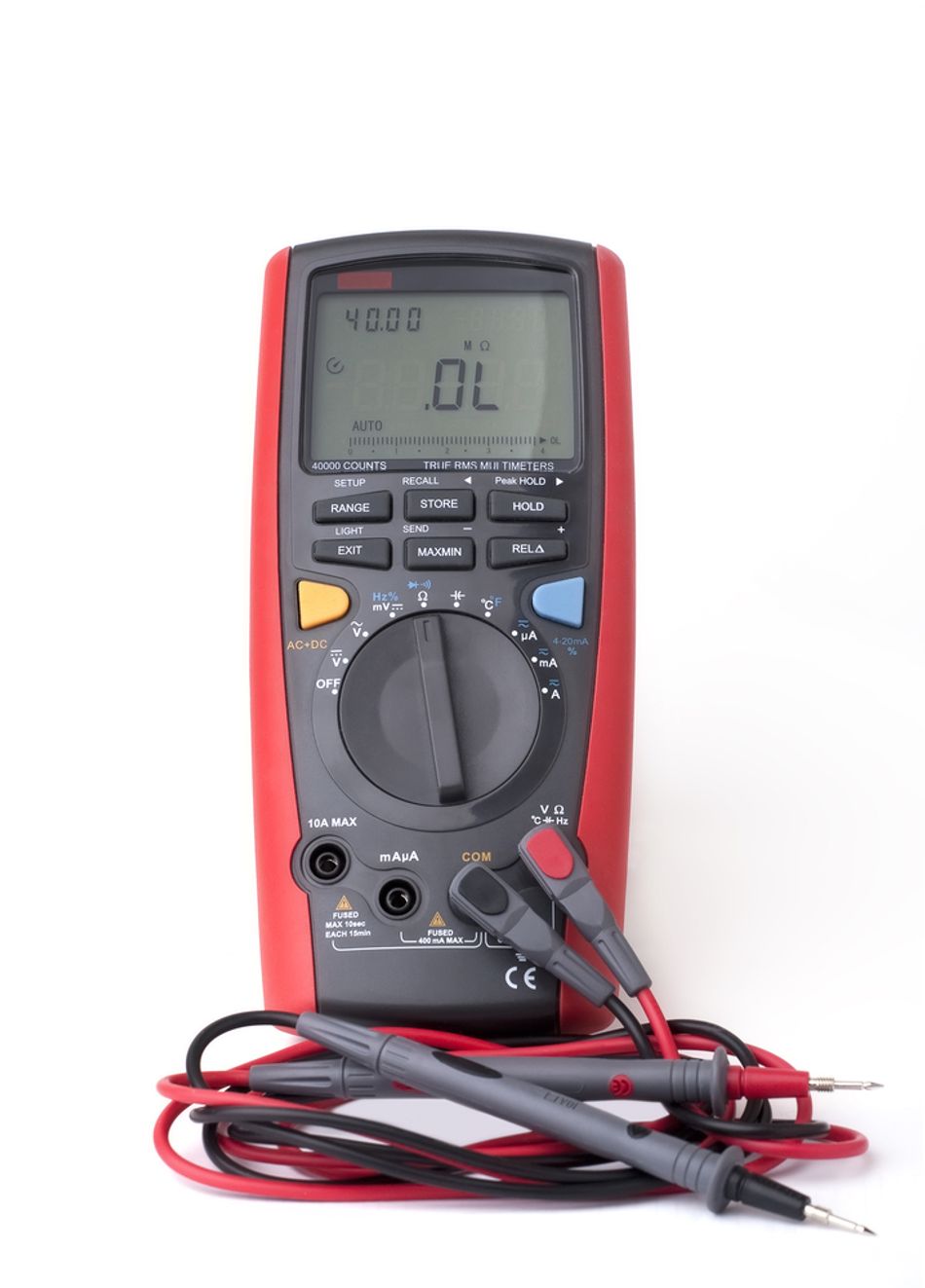
High‑Resolution and Bar‑Graph Modes
Some professional meters provide a HiRes mode (4½ digits) that increases resolution for precision measurement; the icon typically reads “HiRes.” The Fluke 87V also includes an analog bar graph below the digital display. Bar graphs provide a fast visual indication of signal changes, with segments representing the measured value relative to the selected range.
Practical Measurement Techniques
Understanding symbols is just the first step. Correct technique ensures accuracy and preserves equipment. The following best practices incorporate industry guidelines and safety advice from Fluke and other experts.
Pre‑Measurement Checklist
Inspect the meter and leads. Examine the meter case, test leads, and probe tips for cracks, frayed insulation, or other damage. Replace damaged components before use.
Verify operation. Confirm that the meter works by measuring a known voltage source, such as a battery or reference outlet.
Select the proper function and range. Choose the correct symbol for the quantity you’re measuring; for manual‑range meters, select a range higher than the expected value.
Check fuses. For current measurements, verify that the current input fuse is intact. Some meters provide a fuse‑test function; if the meter does not chirp or display “LEAd,” the fuse may be blown.
Use personal protective equipment (PPE). When working on high‑energy circuits, wear appropriate safety glasses, gloves, and arc‑flash gear.
Measuring Voltage Safely
Connect the common first. Attach the black lead to the circuit ground or reference point before probing with the red lead. This reduces the chance of creating a short.
Use one hand when possible. Keep your other hand away from the circuit to reduce the risk of current passing through your body.
Discharge capacitors. Before measuring continuity or resistance, discharge all high‑voltage capacitors to avoid shocks.
Apply LoZ for ghost voltages. If a cable shows unexpected voltage, switch to LoZ mode to see if it disappears; phantom voltage will dissipate through the low impedance.
Measuring Current Safely
Break the circuit. Insert the meter in series with the load; do not connect across a supply. Always turn off the power before breaking the circuit to insert the meter.
Start high. Use the 10 A jack first; if the current is lower than expected, switch to the mA/μA jack for higher resolution.
Mind the fuse rating. Exceeding the current rating will blow the internal fuse; ensure the selected range supports the expected current.
Measuring Resistance, Continuity, and Diodes
Isolate the component. Remove power and, if possible, disconnect one side of the component from the circuit to avoid parallel paths influencing the reading.
Interpret the continuity beep. A beep indicates low resistance; no beep means open. But be aware that some circuits incorporate reactive components that may produce a beep briefly.
Diode polarity. Connect the red lead to the diode’s anode and black to the cathode; swap leads to test reverse bias. A forward voltage around 0.6 V for silicon indicates a healthy diode; “OL” suggests an open junction.
Measuring Capacitance
Discharge thoroughly. A charged capacitor can destroy the meter or cause a shock. Use a resistor or dedicated discharge tool to safely drain the capacitor.
Account for tolerance. Capacitors have a wide tolerance (±20 % for electrolytics). A slight deviation from nominal is normal; a reading far outside tolerance may indicate a failing component.
Using Frequency and Duty Cycle
Slope selection. Many meters allow selecting positive or negative trigger slope; choose the slope corresponding to the rising or falling edge you wish to measure.
Duty cycle. Duty cycle is the percentage of one period in which the signal is active. In Min‑Max mode, you can record extremes and compute averages to gauge PWM stability.
Multimeter Symbol Variations Across Models
Not all meters use identical symbols. Some low‑cost multimeters combine functions on a single position; for instance, a single V symbol may measure both AC and DC with a separate button to toggle. Others include extra symbols like hFE for transistor gain, an RS232 icon for data logging, or a non‑contact voltage detector icon.
Always refer to the user manual of your specific meter to confirm symbol definitions. The following table summarizes some less common symbols and their use.
Symbol | Meaning | Notes |
hFE | Transistor current gain test | Uses a socket to measure hFE of bipolar transistors. |
NCV (lightning bolt or antenna) | Non‑contact voltage detector | Indicates the presence of AC voltage without contacting the conductor. |
dB | Decibels | Measures signal level relative to a reference (600 Ω or 1 mW). |
REL Δ | Delta or relative mode | Sets the current reading as a zero reference. |
Δ% | Percentage deviation | Displays the percentage deviation from a stored reference. |
Backlight (bulb) | Illumination control | Turns on the display backlight. |
Suggested Reading: How to Test a MOSFET: Theoretical Basics and Practical Step-by-Step Guide
Troubleshooting Examples
Example 1: Eliminating Ghost Voltage in a Motor Control Panel
A hardware engineer measures a 48 V control circuit and observes 8 V even when the circuit is off. Suspecting ghost voltage, she switches the meter to Auto‑V/LoZ. The low‑impedance input dissipates stray charge, and the reading drops to 0 V. She confirms there is no live voltage and proceeds safely.
Example 3: Capturing Inrush Current of a Relay Coil
A design engineer wants to measure the inrush current of a relay coil to size a power supply. She enables Min‑Max recording and selects the 250 µs peak response time. As the relay energizes, the meter captures a 3 A peak even though the steady‑state current is only 0.5 A. This informs her design of an adequate supply.
Suggested Reading: What Is In-Circuit Testing? An Essential Guide for Engineers
Conclusion
Modern digital multimeters are powerful diagnostic tools. Understanding the symbols on the dial and display is crucial for engineers and students who need accurate and safe measurements. By recognizing voltage, current, and resistance symbols, using advanced functions like Auto‑V/LoZ, low‑pass filters, and Min‑Max recording correctly, and respecting CAT and IP safety ratings, you can troubleshoot complex systems with confidence. Always follow safe measurement practices—inspect your equipment, select the correct range, connect leads properly, and consult your meter’s manual for specific symbol definitions.
As electronics continue to evolve with higher switching frequencies, mixed‑signal designs, and tighter safety requirements, multimeter features will also advance. Staying up‑to‑date with these developments ensures that your measurements remain reliable and that you can leverage your multimeter’s full potential. Consider exploring meters with data logging, Bluetooth connectivity or built‑in oscilloscopes for even more capability.
Frequently Asked Questions (FAQ)
What does the V with a wavy line (V~) mean on my multimeter?
The V~ symbol represents AC voltage measurement. Use this setting to measure line voltage, AC generator outputs, or any signal that changes polarity periodically.
Can I use the low‑pass filter to verify if a circuit is live?
No. The low‑pass filter blocks high‑frequency components to improve accuracy on noisy AC signals. It should not be used to verify the presence of hazardous voltage. Always measure without the filter first, then enable the filter if needed.
What is the purpose of the Auto‑V/LoZ function?
Auto‑V/LoZ automatically detects whether a voltage is AC or DC and presents a low impedance to bleed off ghost voltages. Use it when you suspect phantom voltage due to capacitive coupling on long cables or unused wires.
How do I measure current safely with my multimeter?
Break the circuit and insert the meter in series. Start with the highest current jack (typically 10 A), then move to the lower ranges if necessary. Always connect the black lead to COM and the red lead to the appropriate current jack, and never exceed the rated current or you will blow the fuse.
Why does my multimeter beep during a continuity test?
In continuity mode, the meter beeps when the resistance between the probes falls below a set threshold (typically 30–50 Ω). The beep confirms a closed path or short circuit.
What does the ‘REL’ symbol do?
REL (relative) mode stores the current reading as a reference and displays subsequent readings as deviations from that value. This helps subtract out offsets or compare small variations without mental calculation.
Are CAT III or CAT IV meters necessary for household work?
For measurements on typical household circuits (plug‑in appliances), a CAT II rated meter is generally sufficient. However, if you plan to work inside distribution panels, on three‑phase equipment or near utility service entrances, choose CAT III or CAT IV to protect against higher transient energies.
References
Fluke Corporation, "The Dials, Buttons, Symbols, and Display of a Digital Multimeter." Available: https://www.fluke.com/en-us/learn/blog/digital-multimeters/multimeter-dial-button-jacks-display
NextPCB, "Multimeter Symbol Explained." Available: https://www.nextpcb.com/blog/multimeter-symbol-explained
The Spruce, "A Complete Guide to Multimeter Symbols." Available: https://www.thespruce.com/multimeter-symbols-8414239
Fluke Corporation, "Guide to Digital Multimeter Safety." Available: https://www.fluke.com/en-us/learn/blog/safety/multimeter-guide
Fluke Corporation, "Dual Impedance Digital Multimeters." Available: https://www.fluke.com/en-us/learn/blog/digital-multimeters/dual-impedance-digital-multimeters
Fluke Corporation, "Fluke 87V Industrial True RMS Multimeter Manual." Available: https://www.familyhandyman.com/article/multimeter-symbol-guide/
Fluke Corporation, "How to Measure Frequency with a Digital Multimeter." Available: https://www.fluke.com/en-us/learn/blog/digital-multimeters/how-to-measure-frequency-with-a-digital-multimeter
Family Handyman, "Multimeter Symbol Guide." Available: https://www.familyhandyman.com/article/multimeter-symbol-guide/
in this article
1. Key Takeaways2. Introduction3. Fundamentals of Multimeter Operation4. Decoding Core Multimeter Symbols5. Understanding Input Jacks and Safety Ratings6. Advanced Functions and Their Symbols7. Practical Measurement Techniques8. Multimeter Symbol Variations Across Models9. Troubleshooting Examples10. Conclusion11. Frequently Asked Questions (FAQ)12. References