Parallel vs Series Circuits: Differences, Theory, and Practical Applications
In this article, we will discuss parallel vs series circuits, exploring how they operate, their key differences in terms of current flow and voltage distribution, and why they are essential in practical designs.

29 Jul, 2025. 17 minutes read
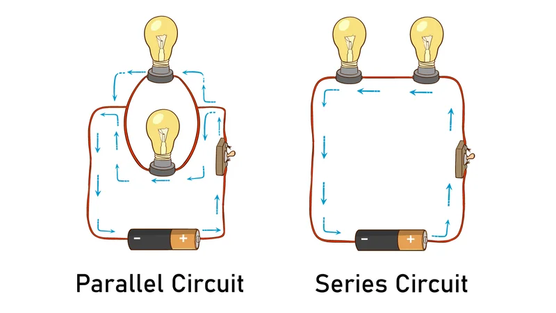
Parallel vs Series Circuit
Introduction
In electrical engineering and circuit design, understanding parallel vs series circuits is fundamental to creating reliable and efficient systems. Both configurations are used extensively, but they exhibit distinct behaviors in terms of current flow, voltage distribution, and overall performance. While comparing parallel vs series circuits, engineers must consider how components interact under different loads and operational conditions.
In a series circuit, components share the same current but experience divided voltages, which can limit flexibility and increase the impact of a single component failure. In contrast, parallel configurations allow components to operate independently with equal voltage across each branch, offering greater fault tolerance and scalability.
The choice between parallel and series circuits directly affects energy efficiency, safety, and design complexity in applications ranging from household wiring to industrial automation. The solid understanding of parallel vs series circuits not only supports better design decisions but also ensures practical implementation in real-world projects!
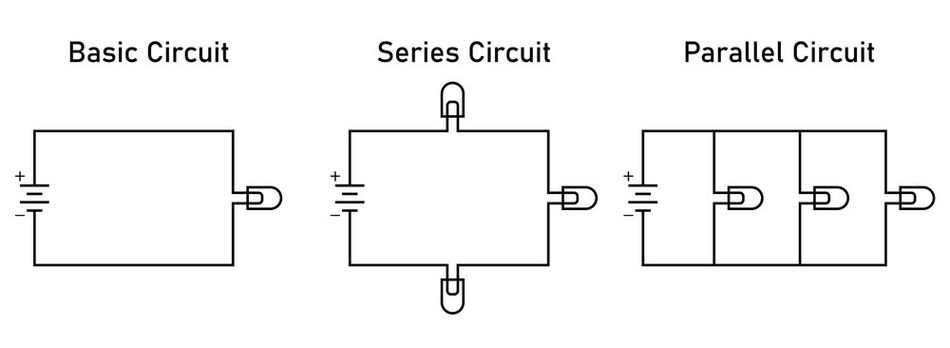
Understanding Series Circuits (One Path, Shared Current)
In a series circuit, components are connected sequentially, end‑to‑end, forming a single unbroken path through which the electric current flows. This means all charges travel through the first component, then the second, and so on – there is only one loop from the positive side of the source, through each component in order, and back to the negative side (ground). Because of this single-path topology, the current is the same at every point in a series circuit.
So, if 2 amperes leave the battery, 2 A flows through resistor R1, 2 A through R2, etc., and 2 A returns into the battery. [1]
Key Properties of Series Circuits
Same Current Throughout
In a series connection, there’s nowhere else for the current to divide, so the current is identical through all components. Mathematically:

This behavior is often summarized as “series = same current.”
Voltage Division
The supply voltage splits among series elements. Each component’s drop is found using Ohm’s Law:

The sum of all drops equals the total supply voltage:

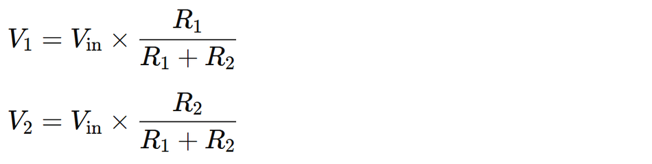
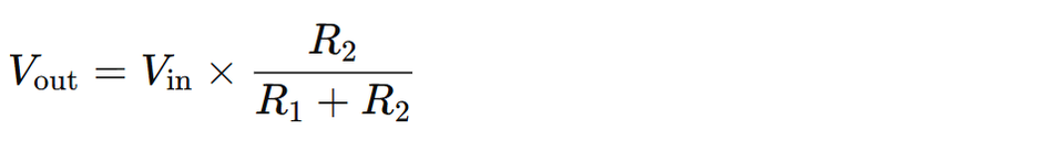
Using a voltage divider for two resistors in series:
Resistance Adds Up
The equivalent resistance of a series circuit is simply the sum of all individual resistance values:

This means adding more components increases total resistance, making it harder for current to flow. In AC analysis, impedances add similarly: series inductors combine directly, while capacitors in series combine via reciprocal addition.
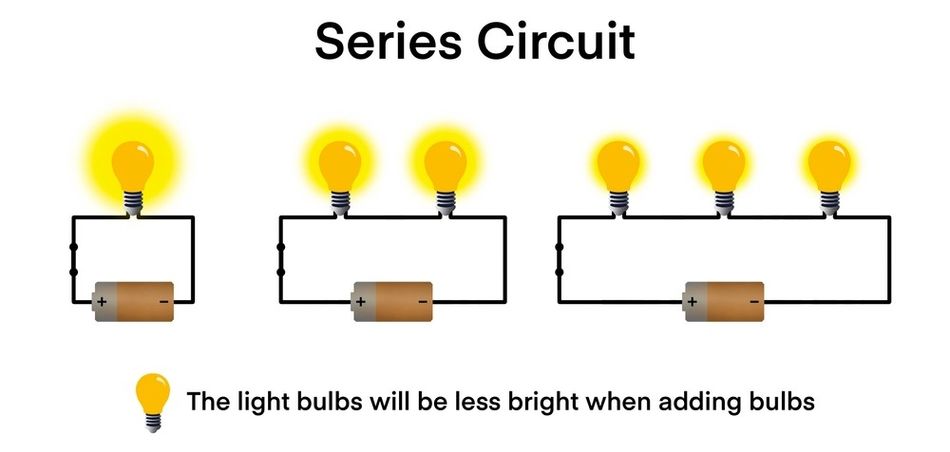
Single Open = Entire Circuit Stops
If there is any break in a series loop, it will stop the flow of current through the whole circuit. A classic example is older string‑type Christmas lights—if one light bulb fails, the entire chain goes dark. In practical terms, individual components cannot be isolated without affecting the whole system.

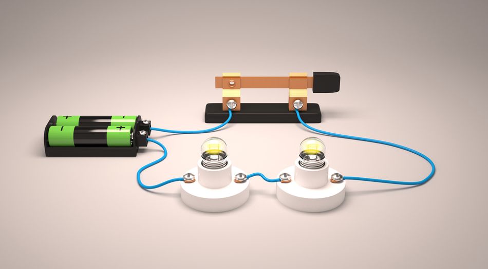
Examples and Applications
Consider a flashlight is a simple series circuit: a battery, a switch, and a bulb connected end‑to‑end. The resistors in series are often used in voltage divider networks to create reference voltages. A resistor in series with an LED is another common design—since the same current flows through both, the resistor limits the current to protect the LED. Multiple battery cells can also be wired in series to increase supply voltage.
It’s worth noting that while series circuits are simple, they are not very fault-tolerant (one failure brings down everything) and adding too many series elements can significantly reduce current due to rising resistance. However, they are useful whenever you need the same current flowing through components – for example, in analog sensing circuits or stringing together battery cells for more voltage.
Theoretical Perspective
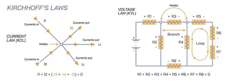
Finally, from a theoratical standpoint, series circuits strictly obey Kirchhoff’s Voltage Law (KVL), which states:

The algebraic sum of all voltage drops and gains must equal zero around any closed loop in an electrical circuit. In a series connection, this means the sum of individual drops across each component—such as resistors, inductors, or even capacitors—always equals the applied supply voltage from the voltage source. This principle underpins critical design methods like the voltage divider, where specific resistance values are chosen to create desired reference levels.
In addition, Kirchhoff’s Current Law (KCL) is trivially satisfied in a series circuit because there are no junctions or branches where the current divides. The same current flows through every element, regardless of whether those elements are passive devices like resistors or reactive components like inductors with certain impedance.
While a series path is simple to analyze in circuit analysis, it is not fault‑tolerant: an open in any part of the circuit interrupts the entire loop, causing the total current to drop to zero. However, due to their predictable behavior, series circuits remain invaluable in applications where a single loop and same current are required—such as analog sensing networks, protection chains, light bulb arrays, and basic ohm’s law demonstrations in educational setups.
Recommended Reading: KCL Circuit Analysis: Advanced Engineering Methods & Best Practices 2025
Understanding Parallel Circuits (Multiple Paths, Shared Voltage)
In a parallel circuit, all components are connected between the same two nodes. In other words, the leads of each component are connected to a common pair of points, forming multiple branches that each go directly across the supply. Because of this configuration, each component in parallel sees the same voltage (equal to the source voltage). [2]
However, the current now has multiple paths: different amounts of current can flow through different branches, depending on each branch’s impedance. The total current from the source is the sum of the branch currents (by KCL).
Key Properties of Parallel Circuits
Same Voltage Across All Branches
By the very definition of a parallel connection, all branches share two common nodes. The potential difference between those nodes is the same for each branch.

If you connect three resistors in a parallel circuit across a 5 V supply, each resistor experiences exactly 5 V across its terminals, regardless of its individual resistance. This is often summarized as “parallel = same voltage.”
A familiar example is household wiring! All outlets and light fixtures are connected in parallel on the main bus. Each appliance plugged in sees the full supply—120 V in some countries or 230 V in others. One appliance drawing more current does not reduce the voltage available to another, provided the power source can supply the necessary amount of current. This is why you can turn on multiple lights or appliances independently without affecting others.
Currents Split (Current Division)
Unlike a series circuit where the same current flows through each component, in a parallel circuit the total current divides among the available paths. Lower resistance branches carry more current, while higher resistance branches carry less.
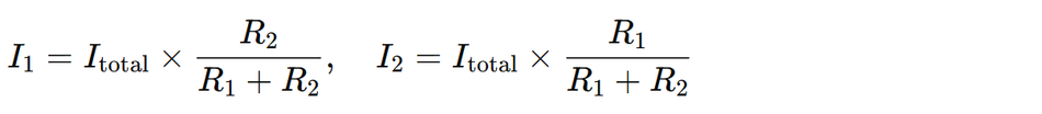
The current division can be calculated with the current divider rule. For two resistors in parallel:
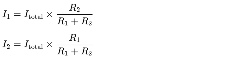
Notice that the value of opposite resistor appears in the numerator, this reflects how a smaller resistor draws a larger share of the current. More generally:

This follows directly from KCL, which states that the sum of currents entering a node equals the sum leaving it. In a parallel network, if one branch is disconnected (open circuit), its current simply drops to zero, while the others continue unaffected. The entire circuit remains operational, which is a significant reliability advantage over a series configuration.
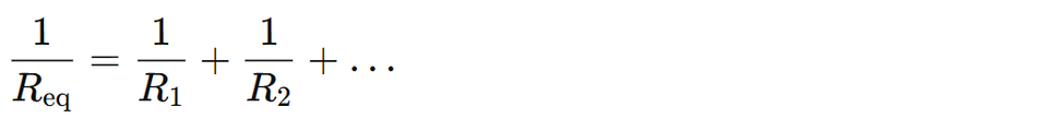
Equivalent Resistance Decreases
One of the defining mathematical properties of a parallel circuit is that adding more branches reduces the overall or equivalent resistance:
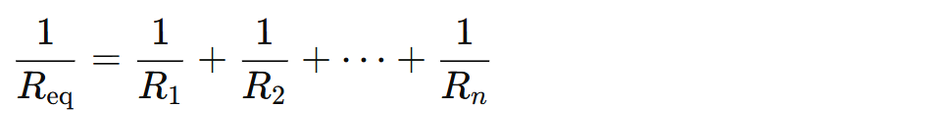
For two resistors:
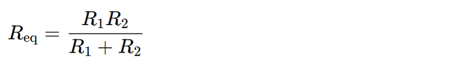
The result is always smaller than the smallest individual resistor. For example, two 100 Ω parallel resistors yield:

Conceptually, think of conductance:
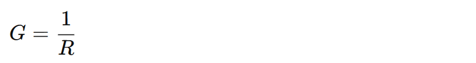
Conductances add directly in parallel, which means adding more branches increases the capacity for electric current to flow. This principle explains why multi-core wires, parallel inductors, or even parallel transistors are used in designs that need to share current and reduce effective resistance.
For other components, the rules are slightly different:
1. Capacitors in parallel simply add:

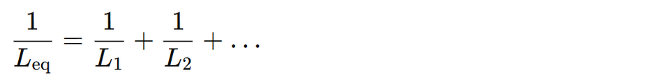
2. Inductors in parallel follow the reciprocal addition formula, similar to resistors:
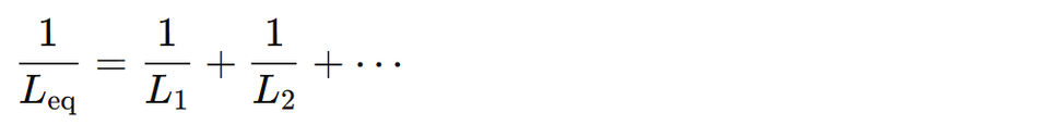
One Branch Open Doesn’t Stop Others
A major advantage of a parallel combination is fault tolerance. If one branch is opened—whether a resistor fails or a switch is turned off—the remaining branches continue to operate normally. Each branch forms an independent path back to the voltage source.
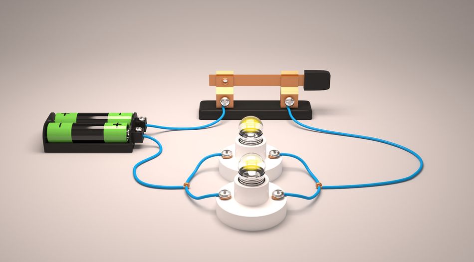
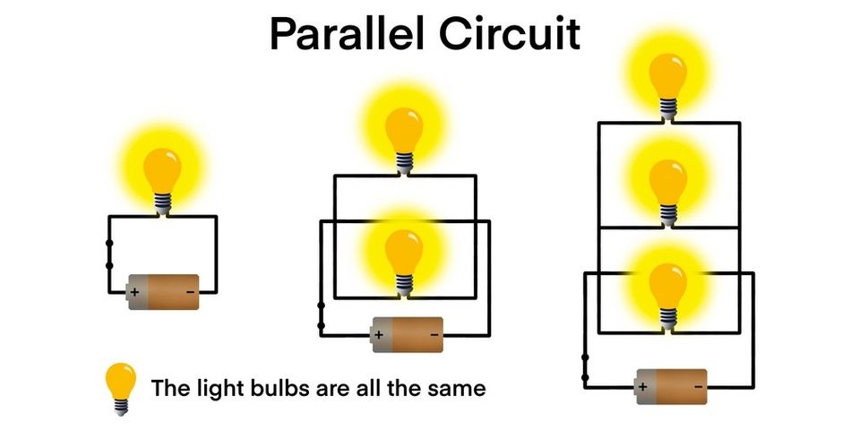
For instance, consider four light bulbs connected in parallel across a 12 V supply. Each bulb receives 12 V and operates independently. If one burns out, its branch current drops to zero, but the other bulbs remain lit. In contrast, in a series circuit, a single open failure would stop the flow of current through the whole circuit.
Practical Examples
Household Wiring: Every outlet and light is part of a parallel circuit. You can turn one lamp off without affecting another, and each device receives full supply voltage.
Automotive Systems: In cars, most components—headlights, dashboard lights, and sensors—are wired in parallel to the 12 V battery. This ensures each device gets the required voltage while allowing independent operation.
PCB Decoupling: Engineers place capacitors in parallel across power and ground to provide a low‑impedance path for high‑frequency noise. Combining different values in parallel improves performance across a range of frequencies, as their combined capacitance adds up. [2]
Current Sharing: Power resistors or even MOSFETs are often paralleled to distribute load and reduce localized heating, leveraging the principle of reduced total resistance.
Theoretical Perspective and Power Considerations
Analyzing parallel circuits relies heavily on KCL at nodes, but Kirchhoff’s Voltage Law (KVL) also applies to each individual loop that includes the source and one branch:

This means the source voltage equals the voltage across any branch element.
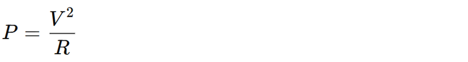
Power behavior also differs between series and parallel circuits. In series, with a common current, components with higher resistance drop more voltage and dissipate more power:

In parallel, with a common voltage, components with lower resistance draw more current and dissipate more power:
For example, three identical resistors across a fixed voltage in parallel will consume more total power and draw more total current than the same three resistors in series. This principle is essential in circuit analysis and power system design, parallel circuits can significantly increase load on the supply.
In summary, a parallel circuit offers consistent voltage across all branches, flexible current division, and excellent fault tolerance. If you are working on household wiring, automotive electronics, or high‑speed PCB design, a solid understanding of these principles is crucial. These properties enables users to apply the above discussed laws, and equivalent resistance formulas confidently, leading to efficient and reliable systems.
Series & Parallel Circuit Comparison
It’s often helpful to directly compare the characteristics of series and parallel circuits.
The table below summarizes the key differences:
| Aspect | Series Circuit | Parallel Circuit |
| Topology | Components connected end-to-end in a single path (chain) | Components each connected across the same two nodes (branches) |
| Paths for Current | Only one path for current flow through all components | Multiple independent paths for current (one per branch) |
| Current | The same current flows through every component | Current splits among branches according to resistance or impedance |
| Voltage | Divided among components; individual voltage drops add to source voltage | Same across each component (equal to source voltage) |
| Resistance (Equivalent) | Increases with more components, making it harder for current to flow | Decreases with more branches, allowing more current |
| Failure/Disconnection | A single open or failed component stops current through the entire circuit | One open or failed branch does not stop other branches; remaining paths still conduct |
| Switching | Series switches act like an AND: all must be closed for current to flow. | Parallel switches act like an OR: any closed branch allows current (one path on keeps circuit powered). |
| Example Applications | Current limiting (e.g. series resistor with LED), voltage divider networks, string lights, old Christmas lights, battery packs for higher voltage. | Power distribution (e.g. home wiring so each load gets full voltage), fail-safe redundancy, multiple LEDs in parallel for uniform brightness, battery banks for higher capacity, decoupling capacitors in parallel for stable supply. |
Choosing Between Series and Parallel
The comparison above clearly shows, neither configuration is inherently “better.” Instead, each serves specific design goals:
Series circuits are ideal when you need the same current through all components, such as in voltage divider networks, current-limiting setups, or when stacking battery cells to achieve a higher overall voltage.
Parallel circuits are preferred when you want every component to receive the same voltage, such as in power distribution systems, lighting networks, or when combining parallel resistors to reduce overall resistance or share current.
In real-world designs, you’ll often see both combined. For example, a large LED lighting system might use strings of LEDs wired in series (to share a uniform current), while multiple such strings are then wired in parallel (so each string receives the same voltage). Similarly, in complex electronic modules, distribution rails are in parallel, while individual sensing elements or resistive components within the module may be in series.
Understanding the fundamental behavior of series and parallel circuits gives you the insight to build reliable, efficient, and safe systems—whether you’re working on simple circuit analysis problems or advanced electrical engineering projects.
Recommended Reading: Types of Circuits: A Comprehensive Guide for Engineering Professionals
Practical Implementations and Design Considerations
Now that the fundamentals are covered, let's explore how engineers apply series and parallel circuits in real-world designs. We will look at several scenarios and the rationale behind choosing series or parallel configurations, often balancing the need for a certain voltage, current, or reliability.
1. Power Sources and Batteries
Batteries in Series vs Parallel: When using multiple battery cells, series and parallel connections serve different goals. Connecting batteries in series increases the total voltage available to the circuit, but does not increase the capacity (amp-hours) or current supply by each cell. For example, two 1.5 V AA cells in series provide 3 V total (useful if a device needs more voltage).

In contrast, connecting batteries in parallel keeps the voltage the same as a single cell, but increases the available current and capacity (the effective amp-hour rating). Two identical 1.5 V cells in parallel still provide 1.5 V, but can deliver roughly twice the current for longer before discharging. This is because parallel cells share the load (each provides part of the current).

Designers must also consider that cells in series must have the same capacity and state-of-charge to avoid imbalance, and cells in parallel should have the same voltage to begin with. It’s common in renewable energy systems (like solar panels and battery banks) to configure sources in series-parallel combinations to reach a desired voltage and capacity. For instance, in a solar installation, you might put panels in series to get a higher DC bus voltage, then parallel strings of those to increase current. The choice of series vs parallel in power sources is thus about trading voltage for current: series = more volts, parallel = more amps!
Power Distribution: Nearly all mains and low-voltage distribution schemes use parallel wiring. This is so each load sees a constant supply voltage and can operate independently. If instead we wired all appliances in series, turning one off (open circuit) would shut off everything – clearly impractical. Additionally, in parallel, each device can draw the current it needs without affecting others (aside from overall load on the source). The Kirchhoff’s laws ensure voltage is consistent across parallel outlets and currents sum at the panel. The only time series wiring is used in power systems is in certain niche applications, like older Christmas lights or decorative series lighting where simplicity and constant current were desired (modern designs even avoid that by using integrated drivers).
2. Electronic Component Networks
Resistors: Using resistors in series or parallel is a basic technique to achieve needed resistance values or power ratings. Series resistors add to a higher resistance; this is useful if you need a value that isn’t readily available as a single resistor. For example, to get ~150 Ω you might put 100 Ω and 50 Ω in series. Series connection is also used to increase power handling – two resistors sharing the voltage will each dissipate part of the power.

On the other hand, parallel resistors are used to get a lower resistance (e.g., two 10 Ω in parallel give 5 Ω) or to share current.
N identical resistors of value R in parallel give R/N equivalent resistance! If you only have many 100 Ω resistors but need ~20 Ω, five of them in parallel will give 20 Ω (and also distribute the current between them). This trick is often used in precision circuits to get an odd value or in power electronics to split heat dissipation across components.
Capacitors: Series vs parallel for capacitors has almost the opposite effect as resistors. Capacitors in parallel sum their capacitance, effectively increasing plate area.

This is extremely common on printed circuit boards for decoupling: designers will place multiple capacitors in parallel across the supply to increase the overall capacitance and to provide low impedance across a broad frequency range. For example, a 10 µF electrolytic capacitor might be placed in parallel with a 0.1 µF ceramic. They both see the same voltage (parallel), and together act to smooth out fluctuations: the large cap handles bulk low-frequency energy, while the small cap responds to fast high-frequency transients. Additionally, using multiple identical capacitors in parallel can lower the effective equivalent series resistance (ESR) and inductance, improving performance. In high-speed digital design, multiple identical decoupling capacitors are often used in parallel to avoid resonant frequency spikes and ensure stable power delivery across frequencies.
Conversely, capacitors in series yield a smaller equivalent capacitance (like resistors in parallel:
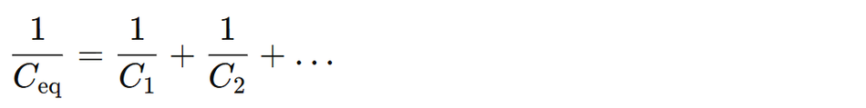
Series capacitors might be used in voltage balancing (e.g., in high-voltage power supplies to split voltage between capacitors) or in creating specific AC networks (like a series coupling or filter network). Each capacitor in series gets the same charge (same current flowed through them) but splits the voltage (similar to resistors splitting voltage).
Inductors: Inductors add in series (like resistors) and diminish in parallel (like resistors in parallel), provided their magnetic fields don’t interact. Series inductors simply sum up (increasing total inductance), which can be used to achieve a desired inductance or to create multi-stage filters.

Parallel inductors provide higher current capacity and reduce the overall inductance:
Designers often use this in power converters to share load current between multiple inductors.
LEDs and Diodes: When driving multiple LEDs, one has to decide whether to put them in series or parallel. In series, one current runs through all LEDs, so they will have the same current (and thus same brightness if identical) – but you need a higher supply voltage equal to the sum of their forward voltages. In parallel, each LED gets the same voltage, but each LED branch needs its own current limiting element (like a resistor) to regulate current, since small differences in LED forward voltage can cause uneven current sharing.
Many LED string lights use series strings (with a single resistor) to ensure equal current, then replicate those strings in parallel to cover more LEDs overall at a given voltage. The design choice weighs simplicity (series uses one resistor for many LEDs but needs higher voltage) versus reliability (parallel means one LED failure doesn’t extinguish them all, but needs individual resistors unless using constant-current drivers).
Voltage Divider vs Current Divider: A voltage divider is a pair (or network) of resistors in series across a voltage source – tapping the junction provides a fraction of the voltage.
This is a series-circuit application for creating reference voltages, sensor scaling, etc. The output is stable as long as the load on the divider is high impedance (so as not to disturb the series current).
On the flip side, a current divider is essentially a parallel network: if you have a certain current entering two parallel resistors, it will split in inverse proportion to their resistances.
This principle appears in biasing circuits, current mirrors, and analog networks, even if not always labeled as a “current divider.”
In analog circuits, sometimes a known current is split using parallel impedance branches (like in bias networks or current mirror circuits in integrated design). While the formula and concept of current division might be less commonly discussed at a basic level, it is directly related to parallel circuits’ behavior – designers use it implicitly when they route currents through parallel paths.
3. Signal Integrity and Termination Networks
In high-speed digital and analog signal design, managing reflections and impedance is crucial. Here, series vs parallel comes into play in termination strategies for transmission lines:
Series Termination: A resistor is placed in series with the signal line (usually near the driver/source). The resistor, together with the output impedance of the driver, forms a series combination that matches the characteristic impedance of the PCB trace. This dampens reflections by slowing the rise time and absorbing energy at the source. The idea is that the wave sees a continuous impedance and any reflection goes back and gets absorbed by the source impedance. Series termination uses the principle of series circuits: the same current must flow through the series resistor and line, so by choosing the resistor appropriately, you control the current/voltage wave that goes down the line. In practice, series termination involves adding a resistor (e.g. 22 Ω) in series with the driver output to match line impedance, preventing ringing. The benefit is low power consumption (no constant draw) but it only works well for a single receiver on the line.
Parallel (Shunt) Termination: A resistor is connected from the signal line to ground (or to the supply for certain types like TTL) at the receiving end, effectively in parallel with the receiver’s input. This provides a path for the signal to dissipate into a matched resistor rather than reflect back. The resistor value is chosen equal to the line impedance typically. This means when the signal reaches the end, it splits: some into the resistor (dissipated as heat), some into the high-impedance input. Parallel termination has a constant resistor to ground at the far end, which draws current continuously (power dissipation). It ensures the voltage at the end doesn’t bounce, at the cost of extra power usage.
There are some other combinations (Thevenin terminations with two resistors to rails, RC terminations, etc.). But, even at the cutting edge of PCB design, the decision to put a resistor in series or in parallel is crucial and is fundamentally the same series vs parallel concept. Series termination is essentially using a series resistor to create a controlled series circuit with the line (no continuous load, but needs correct resistor value). Parallel termination uses a resistor to ground which is permanently in parallel with the receiver (consistent load equal to line impedance, eliminating reflections at the cost of power).
Recommended Reading: Source Transformation in Electrical Circuit Analysis: Thevenin–Norton Equivalence & Circuit Simplification
Future Implications and Final Thoughts
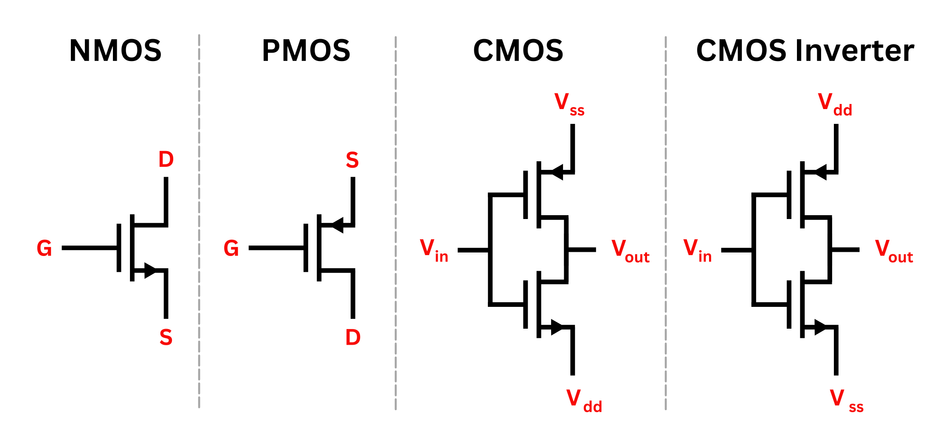
Today, as integrated circuits become ever more complex, the principles of series circuits and parallel circuits remain just as relevant—often at scales invisible to the naked eye. Even within a single chip, the interconnections of transistors follow these same rules. For example, in CMOS logic, transistors arranged in series implement logical AND functions (the same current must pass through multiple devices), while transistors in parallel implement logical OR functions (multiple paths allow current to flow if any device is active).
On the power‑delivery side, modern processors rely on arrays of parallel capacitors to maintain stable supply voltages at multi‑gigahertz speeds. These decoupling networks, often carefully tuned for low impedance, are critical for suppressing noise and ensuring that high‑speed logic can operate without glitches. Likewise, in RF and microwave design, impedance matching networks often use combinations of series and parallel elements—resistors, inductors, and capacitors—to achieve desired bandwidths and minimize reflections. These networks are critical for 5G/6G antennas and high‑bandwidth data links, where reflections must be minimized, and designers often rely on digitally controlled series‑parallel arrays of varactors and MEMS switches. [4]
Even beyond chips and PCBs, the series/parallel paradigm drives innovations in energy systems. Research into modular battery packs for electric vehicles (EVs) shows how dynamic reconfiguration of cells between series and parallel can extend battery life and optimize efficiency under varying load conditions. In renewable energy, engineers combine parallel strings of solar panels with series stacks to achieve both the voltage and current needed for high‑power inverters.
In short, the future of hardware design, spanning advanced processors, high‑frequency communication, and sustainable energy, still relies on your mastery of series and parallel networks. Keep these concepts close, apply them thoughtfully, and you’ll be equipped to push the boundaries of what modern electronics can achieve!
Recommended Reading: How Do Circuit Boards Work: A Comprehensive Guide to the Heart of Electronics
Conclusion
Series and parallel circuits form the backbone of all electrical network behavior. The series circuits funnel current through a single path, causing components to share current and split the voltage, whereas parallel circuits offer multiple paths, causing components to share voltage and split the current. These simple principles – guided by Kirchhoff’s Laws and Ohm’s Law – explain everything from simple lighting setups to advanced impedance‑matched networks. Engineers apply them daily—electing resistor combinations, designing stable power delivery, or creating fault‑tolerant systems. Most complex designs break down into series‑parallel sections, such as series cells grouped in parallel or parallel LED strings with series elements. Mastering these basics enables confident design, analysis, and troubleshooting, even as technology evolves.
Frequently Asked Questions (FAQs)
Q1: What is the main difference between series and parallel circuits?
A: In a series circuit, components share the same current and split voltage along one path. In a parallel circuit, components share the same voltage but split current through multiple independent paths.
Q2: Why is the current the same in a series circuit but not in a parallel circuit?
A: In series, there’s only one path, so the same current flows through all components. In parallel, branches split current based on resistance, with Kirchhoff’s Current Law ensuring total equals the sum of branch currents.
Q3: What happens if one component fails in a series circuit versus a parallel circuit?
A: In series, one failure breaks the circuit and stops all current. In parallel, a failed branch stops only its own current while others continue functioning, maintaining power to remaining branches.
Q4: Are household electrical circuits series or parallel, and why?
A: Household wiring is parallel, so each device gets full voltage and works independently. Turning one off or unplugging doesn’t affect others, unlike series where one open connection would cut all power.
Q5: When should I use a series connection and when a parallel connection in design?
A: Use series to get the same current or higher voltage, like LEDs with a resistor. Use parallel for the same voltage or higher current capacity, like parallel capacitors or battery banks.
Q6: Can I mix series and parallel connections in one circuit?
A: Yes, most circuits are a combination. Complex networks often reduce to series-parallel sections, like series resistor strings in parallel groups, allowing designers to meet specific voltage, current, and reliability needs.
Q7: Do series or parallel configurations affect signal timing or speed?
A: Yes. Series elements add impedance, slowing edges or increasing propagation delay. Parallel branches add capacitance, increasing load and slowing transitions. High‑speed designs carefully balance both for optimal signal integrity.
References
[1] Standford. Chapter 3 - Solving for Voltages and Currents in Circuits [Cited 2024 July 23] Available at: Link
[2] Wevolver. Decoupling Capacitors: Mastering Power Integrity in Electronic Design [Cited 2024 July 23] Available at: Link
[3] EBSCO. Electric Circuits: Parallel vs. Series, Diagrams and Components [Cited 2024 July 23] Available at: Link
[4] MDPI. Highly Adaptive Reconfigurable Receiver Front-End for 5G and Satellite Applications [Cited 2024 July 23] Available at: Link
in this article
1. Introduction2. Understanding Series Circuits (One Path, Shared Current)3. Understanding Parallel Circuits (Multiple Paths, Shared Voltage)4. Series & Parallel Circuit Comparison5. Practical Implementations and Design Considerations6. Future Implications and Final Thoughts7. Conclusion8. Frequently Asked Questions (FAQs)9. References