BLDC Motor Driver: Architecture and Tradeoffs
Electronic power stage and control choices for brushless DC motors.

26 Jun, 2026. 13 minutes read
Key Takeaways
A BLDC motor driver is a three-phase electronic commutator: it energizes the motor windings in the correct sequence so that the rotating magnetic field follows the permanent-magnet rotor.
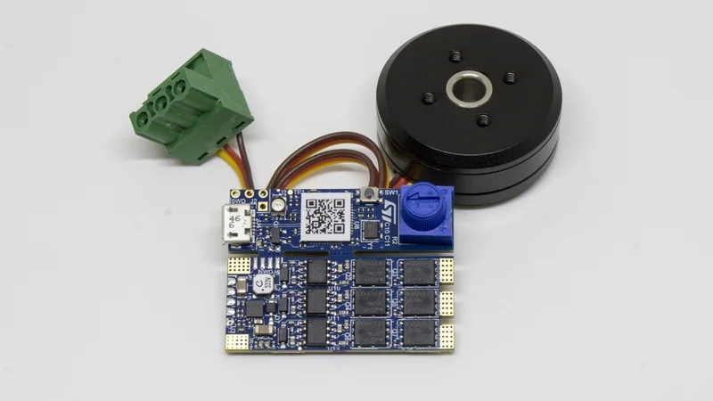
The core hardware consists of a DC bus, a three-phase inverter using MOSFETs or IGBTs, a gate driver, current sensing, rotor position or speed feedback, and a microcontroller or a dedicated BLDC motor controller.
Six-step commutation is simple and robust; sinusoidal control reduces torque ripple; and field-oriented control delivers the best torque, speed, acoustic, and efficiency performance when the application can justify the added sensing and firmware complexity.
Hall-effect sensors are excellent for startup and low-speed operation; sensorless back EMF methods reduce wiring and motor costs but require special startup handling because the back EMF is small at low rotational speeds.
Integrated BLDC motor drivers reduce PCB area and development time; discrete gate-driver-plus-MOSFET designs scale better for high-current, high-voltage applications, thermal constraints, and custom protection.
Practical design quality depends as much on layout, thermal design, current measurement, dead time, EMI control, and fault handling as on the commutation algorithm.
Introduction
A BLDC motor is a brushless synchronous machine with a permanent-magnet rotor and a wound stator. Unlike brushed DC motors, it has no mechanical commutator and no brushes to switch current through the rotating armature. So, the commutator function is implemented electronically. The BLDC motor driver switches the electric current through the motor windings so that the stator magnetic field advances in step with the rotor position.
This article focuses on the driver, not just the motor. The driver is the electronic system that converts DC bus power into controlled three-phase currents. That includes the power stage, gate drive, current-sense network, rotor position sensing or estimation, protection circuitry, and firmware running on a microcontroller, digital signal controller, or dedicated BLDC motor controller. The same design space appears in robotics, drones, actuators, blowers, appliances, washing machines, CNC machines, consumer electronics, and motion control systems.
From Motor Physics to Driver Requirements
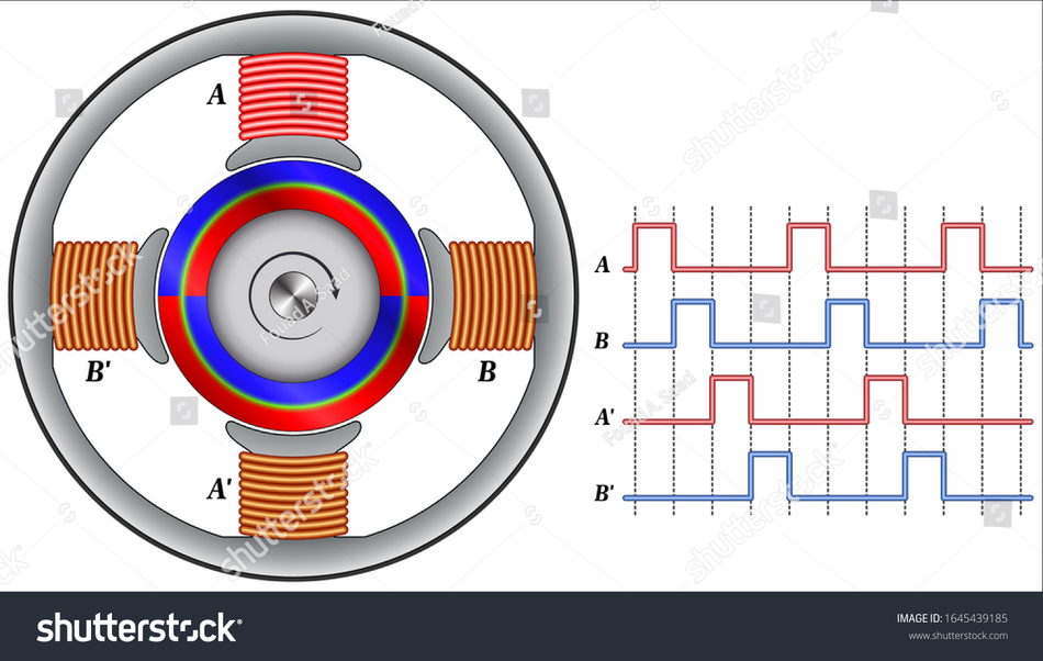
A BLDC motor produces torque by interaction between the rotor's permanent magnet field and the magnetic field generated by stator coils. In a common three-phase motor, the stator has three sets of motor windings, typically connected in a star or delta arrangement, and the rotor has alternating north and south magnetic poles.
The driver's first job is to energize the right winding pair at the right time. In a six-step operation, one phase is driven high, another is driven low, and a third is left floating during each electrical sector. In sinusoidal or field-oriented control, all three phases may be modulated continuously to synthesize a smoother rotating field.
In every case, commutation must track electrical rotor angle, not just mechanical shaft angle. Electrical speed equals mechanical speed multiplied by pole pairs, so a 7-pole-pair outrunner at 10,000 RPM has a much higher electrical commutation rate than a 1-pole-pair motor at the same mechanical speed.
Typical voltage and current ranges vary widely:
Application class | Typical DC bus | Typical current class | Common driver approach |
Small fans, pumps, consumer electronics | 5 to 24 V | Below 0.1 to 3 A | Integrated driver with MOSFETs |
Appliances, blowers, washing machines | 12 to 48 V or rectified mains bus | 1 to 20 A, sometimes higher | Integrated controller or discrete inverter |
Drones and RC ESCs | 2S to 12S battery packs, roughly 7.4 to 44.4 V nominal | 10 to 100 A class in many propulsion systems | Discrete MOSFET ESC |
Robotics, robotic arms, actuators, AGVs | 24 to 72 V common | 5 to 100 A depending on axis | Gate driver plus external MOSFETs |
Industrial servo and compressor drives | 48 to 100 V low-voltage, or 270 to 390 V DC from rectified 195 to 265 V AC in some appliance inverter references | Several amps to tens of amps | MOSFETs, IGBTs, or power modules |
Suggested Reading: Motor Controller: Types, Design Considerations, Control Strategies, and Selection for Engineers
BLDC Motor Driver Architecture
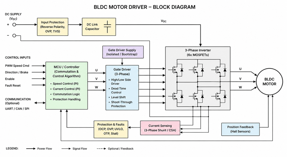
A practical BLDC motor driver has five functional blocks: power input, inverter, gate driver, sensing, and control. The boundary between these blocks changes depending on integration level.
A tiny fan IC may combine most of them into a single package. A drone ESC or industrial servo drive often consists of a microcontroller, a three-phase gate driver, external MOSFETs, current shunts, and protection hardware.
DC Bus and Input Network
The DC bus supplies energy to the inverter. In a battery system, it may be a Li-ion, LiPo, lead-acid, or supercapacitor pack. In an appliance or industrial drive, it may be produced by a rectifier and power factor correction stage.
The input network usually includes bulk capacitance to mitigate motor current ripple, ceramic capacitors near half-bridges for high di/dt loops, reverse-polarity or inrush protection where needed, and an EMI filter when regulatory limits apply.
Three-phase inverter power stage
The inverter usually consists of three half-bridges, one per motor phase. Each half-bridge has a high-side and low-side switch. In low-voltage and medium-voltage designs, those switches are usually N-channel MOSFETs because they offer low on-resistance and good switching performance. In higher-voltage or high-power drives, IGBTs or power modules may be more appropriate, although modern silicon carbide and gallium nitride devices are expanding the feasible range for fast-switching inverters.
The inverter controls phase voltage, not phase current directly. Phase current results from applied voltage, winding resistance, winding inductance, back EMF, rotor position, and control loop behavior. This is why current sensing and PWM timing are central to stable torque control.
Gate driver stage
A microcontroller pin cannot directly drive the gates of power MOSFETs in a motor inverter. The gate driver translates logic-level PWM into high-current gate charge and discharge pulses, generates high-side gate voltage through bootstrap capacitors or charge pumps, enforces undervoltage lockout, inserts or supports dead time, and often reports faults.
Current sensing
Current measurement is the feedback variable that turns a voltage inverter into a torque controller. Common options are:
A single DC bus shunt, lowest cost but hardest to sample correctly at high duty cycles.
Two low-side phase shunts are common in FOC because the third-phase current can be reconstructed using Kirchhoff's current law.
Three-phase shunts: more complete observability but higher cost and amplifier channels.
Inline phase sensing using current-sense amplifiers, Hall sensors, or isolated amplifiers for high common-mode environments.
TI's current-sensing reference design explicitly compares single-, dual-, and triple-shunt methods for a three-phase FOC inverter and notes that accurate current sensing is important for low torque ripple, low audible noise, and dynamic motor control.
Suggested Reading: What Is a PWM Signal? Fundamentals and Practical Applications for Engineers
Controller and firmware
The controller can be a general microcontroller, a motor-control MCU, a digital signal controller, an FPGA, or a dedicated motor-control IC. Microchip dsPIC33 devices, TI C2000 MCUs, STM32 motor-control MCUs, and NXP motor-control MCUs are typical programmable platforms. Microchip's dsPIC33 motor-control page highlights dedicated peripherals and DSP features for sensorless FOC, as well as speed, position, and torque control.
Dedicated controllers reduce firmware burden. TI's DRV10983 integrates power MOSFETs and a proprietary sensorless sinusoidal scheme for 12 to 24 V, low-noise applications up to 2 A continuous.
Recommended Reading: BLDC Motor Controller: Comprehensive Design Guide for Engineers
Commutation and Control Methods
The driver must synchronize stator excitation to the rotor. The three dominant control methods are six-step trapezoidal commutation, sinusoidal control, and field oriented control.
Method | How it drives the motor | Position information | Advantages | Tradeoffs |
Six-step trapezoidal | Two phases conduct per sector; one phase floats; 60 electrical degree sectors | Hall effect sensors or sensorless back EMF zero-crossing | Simple, efficient, low compute, robust for fans and ESCs | More torque ripple, more acoustic noise, less ideal for precision motion |
Sinusoidal control | Phase voltages or currents follow sine waves | Hall interpolation, encoder, estimator, or sensorless IC | Lower torque ripple and quieter operation than six-step | Needs better angle estimate and current control |
Field oriented control | Transforms phase currents into d-axis and q-axis components, controls torque-producing current directly | Encoder, Hall plus estimator, observer, or sensorless estimator | Best dynamic response, low ripple, high efficiency, good speed regulation | More firmware, current sensing, tuning, and CPU or hardware support |
Six-Step Control
Six-step control is still common in drones, simple pumps, fans, and cost-sensitive motor control circuit designs. In a drone ESC, the ESC receives a throttle command, estimates or measures rotor position, generates high-rate PWM, and commutates the motor phases. Multirotor drones favor high power density, rapid throttle response, and low mass.
Sinusoidal Control
Sinusoidal control is used when acoustic noise and ripple are important. It is common in blowers, pumps, appliances, and quiet consumer electronics. FOC is used when torque linearity, efficiency, smooth low-speed operation, or servo performance matter. In robotic arms and CNC machines, FOC, combined with encoders, provides the bandwidth and positioning accuracy expected of a servo motor system.
PWM Control
PWM frequency is a major practical knob. Frequencies below the audible range may produce audible tones, while very high PWM frequencies increase switching losses and can make current sampling more difficult. Many BLDC motor control designs operate in the 8 kHz to 32 kHz range, while specialized controllers and low-inductance motors may operate at higher frequencies. The TMC4671, for example, specifies a fast PWM engine from 25 kHz to 100 kHz.
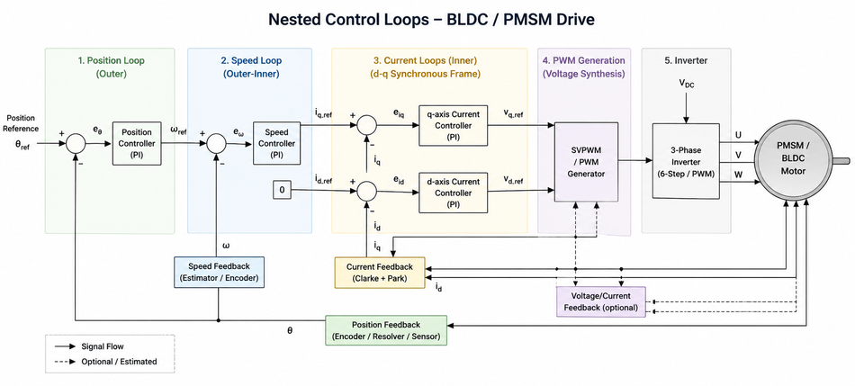
Speed control normally uses nested loops. The inner loop controls phase current or q-axis current, which is closely related to torque. The outer loop compares the commanded rotational speed with the measured or estimated speed and adjusts the current demand. Position-control systems add a third outer loop that commands velocity or torque based on position error.
Recommended Reading: DC Motor Speed Control: PWM Techniques for Brushed and BLDC Drives
Rotor Position Feedback: Hall Sensors, Back EMF, and Encoders
A driver must know where the rotor is, directly or indirectly. The best method depends on startup torque, speed range, cost, wiring, environment, and control algorithm.
Feedback method | Best fit | Strengths | Limitations |
Three Hall effect sensors | Fans, pumps, e-bikes, basic robotics, sensored ESCs | Low cost, deterministic startup, works at zero speed | Low angular resolution, alignment errors, extra wires |
Sensorless back EMF zero-crossing | Drones, blowers, high-speed fans, cost-sensitive products | Removes sensor wiring, good at moderate to high speed | Weak at standstill and low speed, requires open-loop startup |
Encoder | Servo axes, robotic arms, CNC machines, precision actuators | High resolution for speed and position, strong low-speed performance | Higher cost, wiring, mechanical integration |
Resolver or magnetic absolute sensor | Harsh industrial or automotive environments | Robust position feedback, absolute angle options | Interface complexity and cost |
Hall sensor outputs are used to determine commutation sequence and that many motors use three Hall sensors. It also explains that sensorless operation can monitor the back EMF instead of Hall sensors, but because the back EMF is proportional to speed, the motor must start in open-loop until enough back EMF is available for detection.
Back EMF Sensing
Back EMF sensing works naturally in six-step control because one phase is unpowered during each sector, allowing observation of its zero crossing. In FOC, sensorless operation usually uses model-based observers, phase-locked loops, sliding-mode observers, high-frequency injection, or proprietary estimators. These methods can work very well, but they are more sensitive to motor parameters, ADC offsets, current-sense delay, bus voltage measurement, and startup profile.
Encoders
Encoders are often the simplest path to high-performance motion control. Incremental quadrature encoders provide relative motion and speed; absolute magnetic or optical encoders provide rotor position at startup.
In a servo motor application, the motor may be electrically similar to a BLDC or PMSM, but the complete servo system adds high-resolution feedback and a tuned position loop.
Recommended Reading: What is an Encoder: Understanding the Basics and Beyond
Integrated vs Discrete Driver Designs
One of the first hardware architecture choices is integration level. The decision is rarely just cost. It affects current capability, thermal density, firmware ownership, diagnostics, safety case, supply chain, and qualification.
Architecture | Example devices | Best fit | Advantages | Tradeoffs |
Integrated controller plus MOSFETs | TI DRV10983, ST STSPIN830 | Small fans, pumps, compact appliances | Small PCB, fewer external parts, fast development | Limited current and thermal flexibility |
Integrated MCU plus gate driver | ST STSPIN32G4 | Compact custom drives needing firmware control | Combines control MCU and gate driver, reduces BOM | Ties firmware platform to driver IC |
Smart gate driver plus external MOSFETs | TI DRV8300, Infineon 6EDL7141 | Drones, robotics, tools, 24 to 72 V platforms | Scales with MOSFET choice, better thermal layout, diagnostics | More layout burden and component selection |
Dedicated FOC controller plus power stage | ADI TMC4671 | Servo axes, actuators, lab automation, pick and place | Hardware FOC, encoder support, reduced firmware risk | Needs external power stage and system integration |
Fully discrete driver | Gate transformers, isolated drivers, custom comparators | High power, high voltage, unusual environments | Maximum flexibility | Highest engineering effort |
Key Tradeoffs with BLDC Motor Drivers:
Gate-drive strength and switching loss.
A stronger driver charges MOSFET gates faster, reducing switching time but increasing ringing and EMI. Slower edges reduce emissions but raise switching loss. Gate resistors, split turn-on and turn-off networks, Miller clamps, and layout all matter.
Dead Time
Both MOSFETs in a half-bridge must not conduct simultaneously. Dead time prevents shoot-through, but excessive dead time distorts phase voltage and increases diode conduction or synchronous rectification error.
MOSFET Selection
Choose voltage rating with transients in mind, not just nominal bus voltage. A 48 V battery system often uses 80 V or 100 V MOSFETs depending on wiring inductance and surge environment. RDS(on), total gate charge, reverse recovery, package thermal impedance, and avalanche rating all influence real performance.
Thermal Design
A BLDC motor driver usually fails thermally before it fails logically. Losses include MOSFET conduction loss, switching loss, gate driver loss, shunt loss, copper loss in the PCB, and diode or body-diode loss during dead time. Heatsinking, copper planes, airflow, and temperature sensing must be included in the first schematic, not in the final layout patch.
Protection
Minimum protection usually includes undervoltage lockout, overcurrent or short-circuit detection, overtemperature detection, motor lock detection, overvoltage handling during regeneration, and fail-safe PWM states. Some integrated drivers add VDS monitoring, current limiters, fault registers, and diagnostic pins.
How BLDC Drivers Differ From Other Motor Drivers
A BLDC motor driver looks similar to other motor drives because many use PWM, current sensing, and power transistors. The control problem is different, however.
Motor type | Driver topology | Control focus | Relationship to BLDC |
Brushed DC motors | Single switch, half bridge, or H-bridge | Armature voltage and current; brushes handle commutation | Simpler electronics, but brushes and commutator wear and create EMI |
Stepper motor | Two H-bridges for bipolar stepper motor, or unipolar driver | Phase current regulation and microstepping | Good open-loop positioning, but less efficient at high speed and prone to resonance |
BLDC motor | Three-phase inverter | Electronic commutation, speed, torque, or position | Higher efficiency and durability, but requires rotor position handling |
PMSM | Three-phase inverter | Usually sinusoidal FOC | Hardware often overlaps BLDC; waveform and control assumptions differ |
AC induction motor | Three-phase inverter or VFD | Slip, flux, and torque production without rotor magnets | Rugged and magnet-free, but different observer and flux control problem |
Synchronous motors | Three-phase inverter | Rotor-synchronous field control | BLDC and PMSM are permanent magnet synchronous motor variants |
Servo motor | Motor plus feedback plus servo drive | Position, velocity, and torque loop performance | A servo motor may use BLDC or PMSM hardware with encoder feedback |
Brushed DC Motors
Brushed DC motors are easy to drive because mechanical brushes perform commutation. A single H-bridge can reverse direction and control speed with PWM. The cost is brush wear, maintenance, arcing, acoustic noise, and EMI.
Steppers
A stepper motor is usually driven as two controlled current phases. It is excellent for simple positioning without an encoder, but it consumes current even when holding position and loses torque at high speed. A BLDC system is usually better when continuous high-speed efficiency, durability, and power density matter.
PMSM
PMSM and BLDC are close relatives. In practice, many modern BLDC motor drivers can drive PMSM machines, and many FOC platforms treat BLDC/PMSM as the same three-phase permanent magnet control problem. The distinction often comes from back EMF shape and intended drive waveform: trapezoidal for classic BLDC, sinusoidal for PMSM.
AC Induction Motors
AC induction motors require slip to generate rotor current, whereas BLDC motors use permanent magnets. Induction motors are rugged and magnet-free, but BLDC offers higher power density in many compact, energy-efficient designs. In a line-powered appliance, both may use a three-phase inverter, but the firmware estimator and motor model differ.
Application Patterns of BLDC Motors
Drones
Drones and outrunner propulsion. Drone ESCs prioritize mass, current density, fast throttle response, and high electrical RPM. Sensorless operation is common because Hall wires and encoders add weight and complexity.
Robotics
Robotics and robotic arms. Robotics usually values controllable torque, repeatability, and safe fault behavior. A BLDC motor with FOC and encoders can act as a high-performance servo actuator. For collaborative or mobile robots, the driver must handle regenerative energy, torque limiting, thermal derating, and communication protocols such as CAN, EtherCAT, UART, or SPI, depending on the system architecture.
CNC Machines
CNC machines and factory automation. CNC machines need predictable motion, encoder feedback, stiff current loops, and clear fault reporting. Many axes are implemented as servo motor systems using PMSM or BLDC machines with high-resolution feedback.
Conclusion
A BLDC motor driver is a power electronics and control system that replaces the mechanical commutator of brushed machines with timed electronic commutation. The motor itself provides the permanent magnet rotor and wound stator; the driver supplies the sequenced electric current that creates the rotating magnetic field. That simple description hides most of the engineering work: inverter design, MOSFET selection, gate-drive timing, current measurement, PWM strategy, rotor position sensing, firmware control loops, thermal design, and fault handling.
Brushless DC motors are attractive because they can deliver high efficiency, durability, fast dynamic response, and high power density in compact energy-efficient products. The best driver architecture depends on the application. A quiet appliance blower may benefit from an integrated sensorless sinusoidal driver.
FAQs
1. Can a BLDC motor be driven with an H-bridge?
A conventional H-bridge is enough for one brushed DC motor phase, but a three-phase BLDC motor requires three half-bridges, effectively a three-phase bridge. Some single-phase brushless motors use simpler topologies, but most engineering discussions of BLDC motor control refer to three-phase machines. A standard H-bridge article is still useful background because each BLDC phase leg is a half-bridge with similar switching, dead time, and current-path concerns.
2. Are Hall effect sensors better than sensorless back EMF control?
Hall effect sensors are better when the motor must start reliably under load, run at very low speed, or reverse direction predictably. Sensorless back EMF control is better when cost, wiring, sealing, or motor simplicity dominate. Sensorless systems usually need open-loop startup because back EMF is weak at standstill. For precision actuators and robotic arms, encoders or absolute magnetic sensors often outperform both Hall-only and basic sensorless methods.
3. What PWM frequency should a BLDC motor driver use?
Many practical BLDC motor drivers use PWM in the 8 kHz to 32 kHz range, with higher frequencies used when acoustic noise, motor inductance, or control bandwidth require it. Frequencies above 20 kHz can move switching tones beyond typical human hearing, but higher PWM increases switching loss and may worsen EMI. The right value depends on motor inductance, bus voltage, MOSFET switching loss, current-sense timing, and thermal margin.
4. What is the difference between a BLDC motor controller and an ESC?
An ESC, or electronic speed controller, is a BLDC motor controller optimized for speed or throttle control, especially in drones, RC vehicles, and propulsion systems. A broader BLDC motor controller may support torque control, position control, communications, safety functions, encoder feedback, and industrial diagnostics. In drones, the ESC typically receives throttle commands from a flight controller and handles high-current commutation locally.
5. Should I choose an integrated BLDC motor driver or a discrete design?
Choose an integrated driver when board area, time to market, low component count, and modest current levels are priorities. Choose a discrete gate driver and external MOSFETs when current, voltage, thermal spreading, switching behavior, or protection requirements exceed integrated limits. Integrated parts are often best for fans, pumps, and consumer electronics. Discrete designs dominate higher-current drones, robotics, power tools, and custom industrial drives.
6. What protection features are most important in a BLDC motor driver?
Minimum protection should include undervoltage lockout, overcurrent detection, thermal shutdown or derating, shoot-through prevention, locked-rotor handling, overvoltage or regeneration handling, and safe behavior when a phase is disconnected or shorted. Higher-reliability systems also include shunt-amplifier diagnostics, MOSFET VDS monitoring, watchdogs, redundant fault paths, and communication fault handling. Protection thresholds must be validated on real hardware, not only in simulation.
References
Microchip Technology, AN885: Brushless DC (BLDC) Motor Fundamentals
Texas Instruments, DRV8300: 100-V Three-Phase BLDC Gate Driver Datasheet
Texas Instruments, DRV10983: 12- to 24-V, Three-Phase, Sensorless BLDC Motor Driver Datasheet
Analog Devices, TMC4671 Fully Integrated Servo Controller with Field Oriented Control
Infineon Technologies, MOTIX 6EDL7141 Three-Phase Motor Control Gate Driver IC
IEC, IEC 61800-3:2022 EMC Requirements and IEC 61800-5-1:2022 Safety Requirements
in this article
1. Key Takeaways2. Introduction3. From Motor Physics to Driver Requirements4. BLDC Motor Driver Architecture5. Commutation and Control Methods6. Rotor Position Feedback: Hall Sensors, Back EMF, and Encoders7. Integrated vs Discrete Driver Designs8. Key Tradeoffs with BLDC Motor Drivers:9. How BLDC Drivers Differ From Other Motor Drivers10. Application Patterns of BLDC Motors 11. Conclusion12. FAQs13. References