Actuator Motor: Differences Between Actuators and Motors, Selection, and Applications
This guide is an engineering reference on how electric actuators combine motors, gear trains, and mechanical conversion to produce controlled linear or rotary motion, with selection criteria and practical actuator motor applications across engineering systems.

29 May, 2026. 15 minutes read
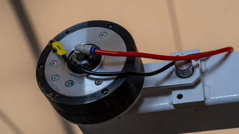
Industrial Rotary Actuator with Pneumatic Hose, Automated Machinery Component
Key Takeaways
Motors vs Actuators: The motor is a rotary energy converter, while an actuator is a complete subsystem that converts an input (electrical, hydraulic, or pneumatic) into a defined mechanical output (linear stroke, rotational angle, or controlled rotation) with built-in transmission and often feedback.
Electric Linear Actuators - 4 Blocks: DC, BLDC, or stepper motor drives a gear train, which drives a lead screw or ball screw, converting rotation into linear travel. The position feedback (potentiometer, Hall sensor, or encoder) closes the loop for accurate positioning.
Motor Selection Character: Brushed DC actuators are cheap and simple but limited in life. BLDC actuators offer higher efficiency and longer service life. Stepper-driven actuators give open-loop positioning. Servo actuators give closed-loop precision under load.
Design Constraints: Force scales with motor torque and gear ratio; speed scales inversely. Stroke is bounded by the screw length. Duty cycle limits thermal load. A 12 V actuator pulling 200 lbf at 0.6 in/s with 25% duty is a different machine from one moving 50 lbf at 2 in/s continuously.
Applications and Domain: Automotive seat and tailgate adjustment, industrial valve control, medical bed positioning, robotic joints, aerospace flaps. Standalone motors are preferred where the load is continuous rotation (fans, pumps, conveyors) and external transmission is acceptable.
Compliance and Standards: IP ratings for ingress protection, IEC 60034 for rotating-machine performance, automotive AEC-Q100/Q101 for component qualification, and ISO 13849 for machine safety apply when actuators or their motors are deployed in regulated environments.
Introduction
Engineers comparing an "actuator motor" against a bare motor often discover that the two terms describe different layers of the same problem: how to turn electrical energy into useful mechanical work. The motor is a rotary energy converter at the core, while an actuator is the integrated subsystem that takes a motor, adds transmission and often feedback, and presents a defined mechanical output to the rest of the machine.
The phrase "actuator motor" is most commonly used in two contexts. The first is the motor in an electric linear actuator, one of several components selected together with the gear train, the lead screw, and the feedback element. The second is shorthand for a complete electric actuator product sold as a single unit. In both cases, understanding the motor and the surrounding mechanics together is essential for sizing, integration, and reliable operation.
This article explains the differences between actuators and motors, key selection factors, and practical actuator motor applications across engineering systems.
What Is an Actuator? What Is a Motor?
Motors - Rotary Energy Converters
The motor converts electrical energy into rotary mechanical energy. The output is torque at a shaft, rotating at a speed set by the electrical drive, the load, and the electromechanical constants of the motor.
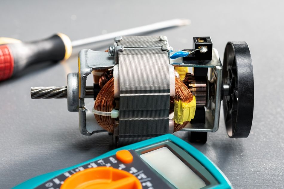
Motors are characterised by stall torque, no-load speed, peak power, efficiency, and electrical input requirements. These inputs may include DC voltage, AC line power, three-phase commutation, or stepped excitation. The brushed DC motor at 12 V might develop 0.1 N·m at 6,000 RPM no-load and stall at 0.6 N·m, drawing tens of amps. BLDC motor of similar size delivers comparable mechanical output with higher efficiency and longer life because brush wear is eliminated.
The motor on its own does not constrain the load. It mainly provides rotational motion. If an application requires slow linear motion, precise positioning, controlled stroke length, or high-force output, additional mechanical and control elements are required. These may include a gearbox, lead screw, feedback sensor, limit switches, and a control system.
Actuators - Integrated Motion Subsystems
The actuator converts an input (electrical, hydraulic, or pneumatic) into a defined mechanical output: linear stroke, a bounded rotation, or controlled continuous rotation at low speed and high torque.
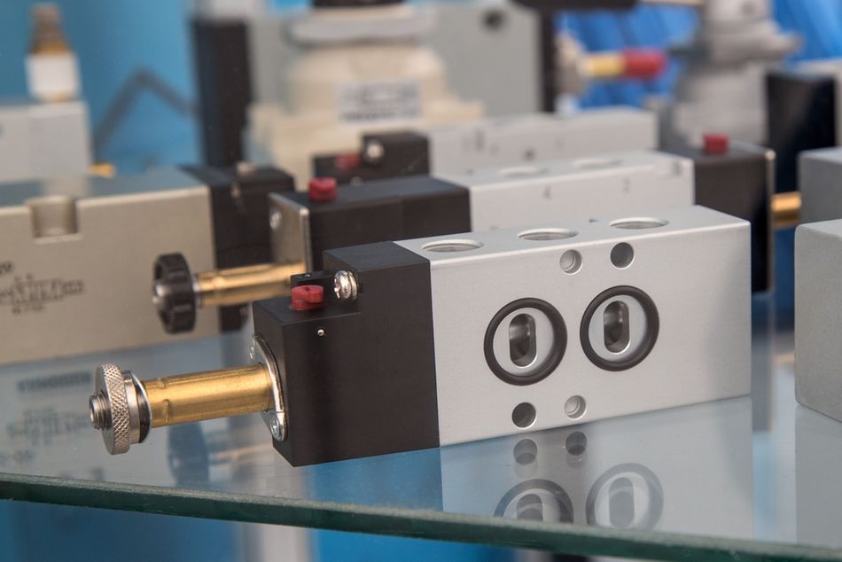
The electric linear actuator typically contains:
Motor (brushed DC, BLDC, or stepper)
Gear Train (spur, planetary, or worm) that reduces speed and multiplies torque
Lead Screw or Ball Screw that converts rotation to linear travel
End Limit Switches that prevent over-travel
Optional Position Feedback (potentiometer, Hall sensor, magnetic or optical encoder)
Mounting Clevises or Brackets sized for the rated load
Unlike a standalone motor, an actuator is specified by the output conditions required by the mechanical device. [1] These include force in newtons or pounds, stroke length in millimetres or inches, speed in mm/s or in/s, positioning repeatability, duty cycle, load capacity, and environmental durability. In practical terms, the actuator is selected for what it does to the load, not only for what its internal motor can produce at the shaft.
Why the Distinction Matters in Practice?
The designer who orders a "motor" for a tailgate lift will not have a working subassembly. They will have a rotor, a stator, and shaft bearings. The mechanical advantage, travel limits, safety interlocks, and closed-loop control must all be designed and integrated. Ordering an "actuator" delivers the integrated subsystem ready to be bolted into the vehicle and driven by a 12 V signal. The premium covers the engineering work bundled within the housing.
This is why the term "actuator motor" appears in two industries with different meanings. In robotics, an actuator motor may refer to a BLDC motor within a servo or a harmonic-drive joint module used in robotic arms. In home automation, automotive seating, medical devices, or TV lifts, an actuator motor may describe the complete electric actuator assembly sold as a single unit.
Recommended Reading: Motor Control Design: End-to-End Methodology
Anatomy of an Electric Linear Actuator
The electric linear actuator converts the rotary output of an electric motor into controlled linear motion. The actuator designs vary by load capacity, stroke length, duty cycle, and environmental rating, but most units follow the same internal architecture. The main functional blocks are the motor, gear train, screw mechanism, position feedback system, and mechanical housing.
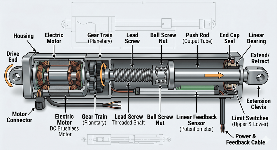
Motor
The motor sits at one end of the actuator. Brushed DC motors dominate the consumer and light-industrial segments because they are inexpensive, run directly from a DC supply, and reverse direction by reversing polarity. BLDC motors are used in higher-end, continuous-duty actuators because they have no brushes to wear out, run cooler, and offer higher torque density. Steppers are used where open-loop positioning is acceptable and the absence of feedback simplifies the drive electronics. Industrial servo actuators use AC or DC servomotors with encoders for high-precision, closed-loop motion.
The typical motor parameters that shape actuator performance:
Stall Torque sets the maximum static force after gear and screw reduction
No-Load Speed sets the maximum linear travel speed
Torque Constant Kt and back-EMF constant Ke govern transient response and the relationship between current and force
Thermal Time Constant governs how long peak force can be sustained before insulation rises to its limit
The motor is therefore not selected only by voltage or power rating. It must be matched to the gearbox, lead screw, duty cycle, load capacity, and control system requirements of the complete actuator.
Gear Train
The gear train lies between the motor and the screw mechanism. Its primary function is to reduce motor speed and multiply torque. This allows a small, high-speed motor to produce the high-force output required to move a load in a controlled straight line.
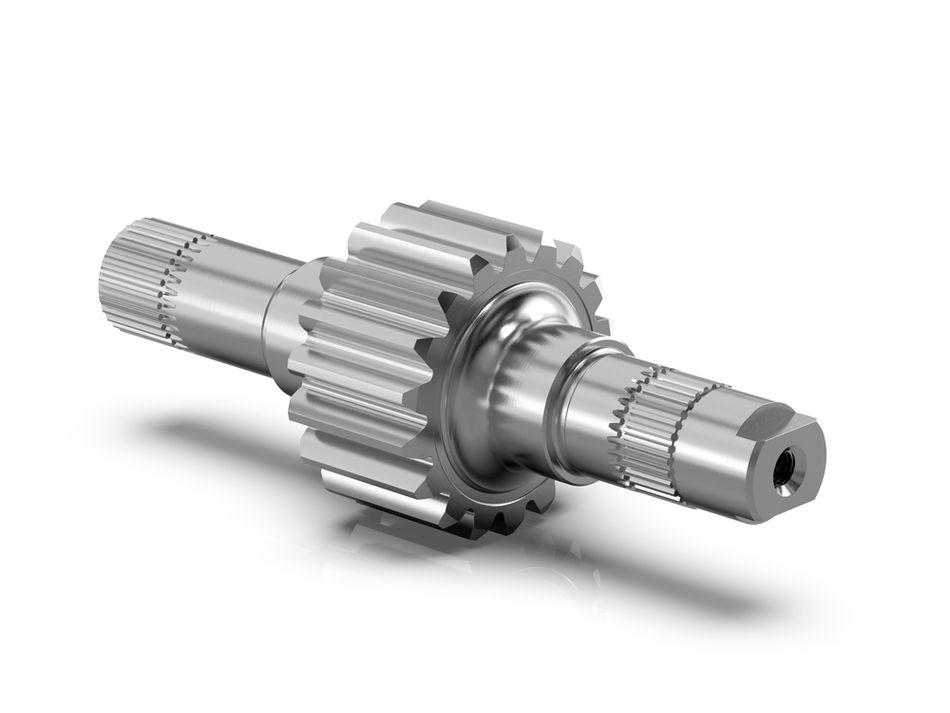
The spur gears are used in simple, low-cost actuator designs. Planetary gearboxes are preferred for compact size, high torque density, and improved efficiency. Worm gearboxes are used when self-locking functionality is important, allowing the actuator to hold position after power is removed.
The typical reduction ratios in electric linear actuators range from 10:1 to 100:1, although heavy-duty or high-force models may use higher ratios. [2] The selected ratio directly affects actuator speed and force. Higher gear reduction increases output force but reduces travel speed, while a lower reduction supports faster movement with less force multiplication.
The gear efficiency at the operating point ranges from roughly 60% for worm to 90%+ for planetary. This efficiency directly enters the force calculation: the rated output force equals motor torque times reduction ratio times screw mechanical advantage, all multiplied by the combined efficiency of the train.
Lead Screw or Ball Screw
The screw converts rotation to linear travel. The two families dominate:
Acme Lead Screws with sliding-contact threads. Cheap, compact, often self-locking, low efficiency (typically 30%–50%). Suitable for low duty cycle and modest precision. [3]
Ball Screws with recirculating ball bearings between the screw and nut. High efficiency (90%+), low backlash, low wear. Required for high-speed, continuous-duty, or precision actuators. Not self-locking, so a brake may be needed.
The screw lead (distance travelled per revolution) sets the mechanical advantage and the speed. For example, a 5 mm lead at 60 RPM yields 5 mm/s of linear travel and trades force for speed compared with a 2 mm lead at the same rotation rate. Therefore, screw lead selection is a direct trade-off between speed, force, precision, and load-holding capability.
Position Feedback and Limit Protection
The closed-loop actuator control requires feedback. Without feedback, the control system can energise the motor, but it cannot accurately verify the actuator’s position, travel distance, or movement error.
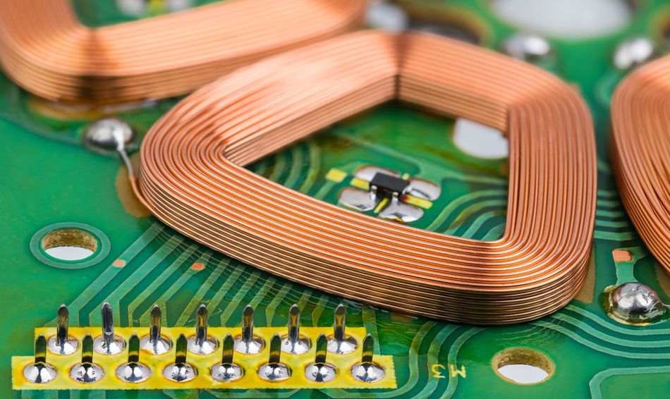
The common feedback options include:
Potentiometers: Provide absolute position feedback along the stroke. They are low-cost and simple but have limited resolution and may wear over millions of cycles.
Hall-Effect Sensors: Count magnetic pulses from the motor shaft or gearbox. They are robust, compact, and suitable for many DC actuator systems, but they are incremental and normally require a reference point or home switch.
Magnetic or Optical Encoders: Provide higher-resolution position data and are used in servo actuators, robotic arms, precision automation, and medical devices.
Limit switches at the end of travel prevent the motor from stalling against the screw stop and burning out.
Mechanical integration
The clevis pins, mounting flanges, and brackets are sized to the rated load. IP rating (e.g. IP65, IP69K) defines protection against dust and water ingress. Materials and seals determine the temperature range.
Recommended Reading: What is an Actuator? Types, Principles, and Applications
Motor Types Inside Electric Actuators
The choice of motor topology inside an actuator drives the cost, lifetime, control complexity, and dynamic performance of the finished product.
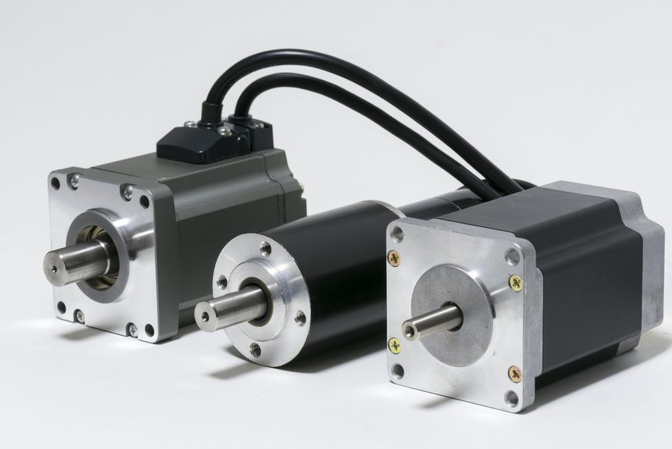
Brushed DC
The brushed DC motor with permanent-magnet field is the simplest actuator drive. The H-bridge in the control board reverses polarity to reverse stroke direction. Speed is controlled by PWM. The drawback is brush wear: after 1,000 to 10,000 hours of operation, depending on the load, brushes degrade, and contact resistance increases. Most consumer linear actuators rated for occasional duty (seat adjustment, TV lifts) use brushed DC.
Brushless DC
BLDC replaces the brushes with electronic commutation. The controller switches the three motor phases in sequence, using rotor position data from internal Hall sensors. The result is longer life, higher efficiency, lower acoustic and electrical noise, and the ability to run at higher continuous duty. The cost is a more complex driver. BLDC actuators are standard in medical positioning beds, factory automation, and modern robotics.
Stepper
The stepper motor advances by discrete steps (typically 1.8° or 0.9° per full step). With microstepping, resolutions of 1/256 of a step are achievable. [4] The advantage is open-loop positioning: send pulses, count steps, know the angle. The drawback is that under high load the motor can lose steps without the controller knowing, unless an encoder is added. Steppers are common in low-cost positioners and 3D printer extruders, but less so in load-bearing linear actuators.
AC Servo and High-End Industrial
Industrial actuators in CNC machines and high-precision robotics use AC servomotors with absolute encoders, driven by vector-control drives. Forces in the kilonewton range and positioning accuracy in single microns are achievable. The complexity and cost are proportional.
Recommended Reading: Brushless vs Brushed Motor: Engineering Trade-offs and Design Decisions
Actuator vs Motor: When to Choose Which?
The decision between specifying a motor with external transmission versus specifying a complete actuator depends on integration burden, certification, and lifetime cost.
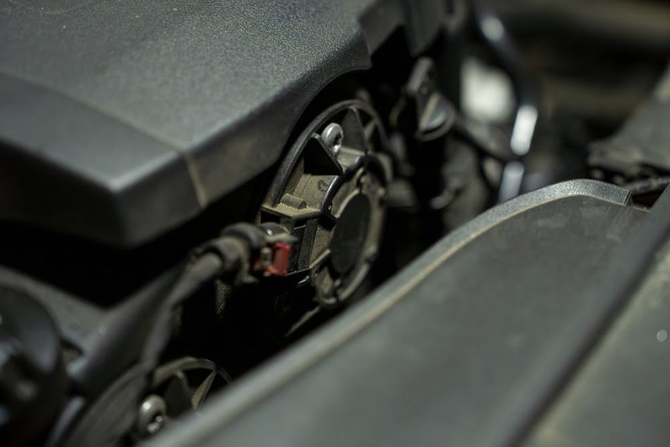
Choose an Actuator When
The required output is linear travel, push-pull motion, or bounded rotary motion
Force, stroke length, and speed can be specified in mechanical terms
The supplier can provide the complete assembly, including gearbox, screw, feedback, and protection features
IP rating, safety certification, or environmental ruggedness are required
The system operates in known applications such as vehicle adjustment, valve actuation, medical positioning, home automation, smart home furniture, or TV lifts
Time to market is more important than complete in-house optimisation
The application needs built-in limit switches, sealed housing, controlled retract/extend movement, or simple 12 volt operation
For many electric actuators, the key benefit is reduced integration risk. The supplier has already matched the electric motor, gearbox, screw mechanism, enclosure, and mounting interface. This is valuable in automotive systems, medical devices, industrial applications, and heavy-duty equipment where reliability and durability are critical.
Choose a Motor with External Transmission When
The load requires continuous rotational motion, such as fans, pumps, conveyors, compressors, grinders, or rotary tools
Custom kinematics rule out catalogue actuator geometry
The mechanism requires a custom belt drive, screw, rack-and-pinion, cam, or gearbox arrangement
Production volume justifies the cost of designing the motor, transmission, feedback, housing, and control system in-house
The application needs direct control over motor parameters such as torque ripple, holding torque, regenerative behaviour, peak overload, acceleration, or commutation strategy
The design requires specialised thermal management, acoustic tuning, or integration with a broader motion control platform
This approach is common in robotics, factory automation, CNC equipment, and custom industrial machinery where the actuator must be built around the machine rather than selected as a catalogue product.
Worked Sizing Example: Automotive Tailgate Lift
Consider a tailgate lift on a light commercial vehicle. The system must raise a 60 kg load through 400 mm of travel in 5 seconds, hold position when de-energised, and survive 50,000 operating cycles from –30°C to 85°C.
Required Force: 60 kg × 9.81 m/s² × 1.5 (safety factor) = 883 N at the actuator output
Required Speed: 400 mm / 5 s = 80 mm/s
Required Holding: Yes, so a self-locking lead screw or a brake is needed
Lifetime: 50,000 cycles × 800 mm round trip = 40 km of accumulated stroke
Environment: Outdoor, sealed to IP65 minimum, full automotive temperature range
The catalogue 12 V electric linear actuator, rated at 1,000 N, 90 mm/s, with an Acme lead screw, IP65 sealing, and a 25% duty cycle would meet the requirements. The bare motor specification at the same force and speed would also require specifying the gearbox, screw, limit switches, sealing, and mounting hardware, plus integrating and qualifying the assembly. For automotive volumes of tens of thousands of vehicles per year, the catalogue actuator is usually the right answer.
Selection Criteria for Electric Actuators
Once specifying an actuator, the following parameters bound the choice:
Force
Rated force is given as static load capacity in pull and push directions. Dynamic force at speed is lower because the motor cannot develop full stall torque while drawing the current required to hold against load. The datasheets typically give a force-speed curve: at maximum speed, available force is reduced.
Stroke
The length of linear travel, from fully retracted to fully extended. Compact actuators offer 50 mm to 300 mm; long-stroke industrial units extend to 1 m or more. Stroke is bounded by the screw length and the housing geometry; longer strokes increase both cost and column-buckling risk under push load.
Speed
Linear travel speed under no load. Speed decreases with load; the force-speed curve is approximately linear between stall (zero speed, peak force) and no-load (maximum speed, zero load force).
Duty Cycle
The percentage of time the actuator can operate before thermal limits force a cooldown. 25% duty actuator can run 15 minutes out of every hour at rated load. The continuous-duty actuators are heavier and more expensive because they have larger motors and better heat sinking.
Voltage and Current
Most mobile actuators run on 12 V or 24 V DC. Industrial actuators use 24 V DC, 48 V DC, or 230 V AC. Current draw at rated load determines the supply and cable sizing. The 12 V actuator drawing 5 A continuously requires an 8 AWG (3.3 mm²) cable for runs longer than a couple of metres to limit voltage drop.
Positioning Accuracy and Repeatability
Actuators with potentiometer feedback are accurate to roughly 0.5% of stroke. Hall-sensor actuators counting motor pulses can resolve to fractions of a millimetre. Servo actuators with encoders push to micron-class repeatability.
IP Rating
IP54 keeps out dust and splash water; IP65 is rated for jets; IP69K survives high-pressure washdown. [5] Outdoor and washdown environments push toward higher ratings.
Temperature Range
Indoor industrial use typically ranges from –10°C to 50°C. Outdoor automotive and aerospace push to –40°C to 85°C or wider, with lubricants and seals chosen accordingly.
Mounting and Load Path
The actuators usually mount via clevis pins at both ends, allowing self-alignment. Side loads on the push rod must be kept low because the screw and rod bushings are not designed for radial loads.
Applications
Electric actuators dominate in applications where motion needs to be precise, repeatable, and quietly integrated into a larger machine.
Automotive
In automotive systems, electric actuators are used wherever compact motion, controlled force, and reliable positioning are required from a 12-volt power source. Power seats use actuators for forward-backward travel, height adjustment, recline control, and memory positioning. Power tailgates and liftgates use electric linear actuators to raise, lower, and hold heavy panels safely. Smaller actuator assemblies are used for headlight levelling, HVAC vent and flap control, fuel-door mechanisms, active grille shutters, and adaptive aerodynamic surfaces. In these applications, durability, quiet operation, temperature resistance, and precise control are critical because the actuator must perform reliably over thousands of cycles.
Industrial Automation
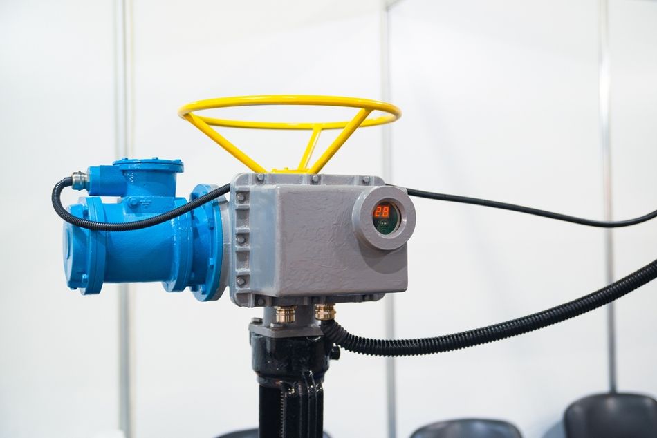
In industrial automation, actuators are used to move machine elements with repeatable force, speed, and stroke length. Valve and damper actuation in process plants often relies on electric actuators where clean operation and electronic control are preferred over compressed air or hydraulic power. Machine guarding doors, access panels, material-handling diverters, lift gates, press positioners, and feed mechanisms also use actuators to control motion in production lines. These industrial applications often require heavy-duty construction, high-force output, long lifespan, limit switches, and compatibility with PLCs or other motion control systems.
Medical and Assistive
Medical devices use electric actuators because they provide smooth, quiet, and controlled movement without hydraulic fluid leakage or compressed-air infrastructure. Hospital and care-home beds use multiple actuators to adjust head position, knee elevation, bed height, and Trendelenburg angle. Patient lifts, transfer aids, adjustable examination tables, dental chairs, and rehabilitation equipment use actuators to provide safe positioning under load. In these systems, precise positioning, low noise, high durability, and reliable load capacity are essential because the actuator directly affects patient comfort, safety, and clinical functionality.
Robotics and Motion
In robotics and motion systems, actuators provide controlled movement for linear axes, joints, grippers, and tool-changing mechanisms. Cartesian robots use electric linear actuators or ball-screw-driven stages to generate accurate straight-line motion along X, Y, or Z axes. Collaborative robots, exoskeletons, and robotic arms use compact actuator modules that combine an electric motor, gearbox, feedback sensor, and control electronics. Gripper jaws use small actuators for controlled opening and closing, while tool changers use actuators for locking and release functions. These applications demand precise control, fast response, repeatability, and strong integration with servo drives or feedback-based control systems.
Aerospace and Defence
These applications use actuators where high reliability, compact packaging, and controlled movement are required under demanding environmental conditions. Aircraft systems may use actuators for flap, slat, spoiler, trim, and cargo door operation, while defence platforms use them for weapons bay doors, turret elevation, targeting systems, and controlled access mechanisms. Spacecraft and satellites use specialised actuator systems for deployment mechanisms, antenna positioning, solar array movement, and instrument alignment. These applications often require lightweight materials, vibration resistance, thermal stability, redundancy, and compliance with strict industry standards.
Renewable energy
The renewable energy systems use actuators to improve energy capture, safety, and automated operation. Solar trackers use electric actuators to adjust panel angle throughout the day, helping the system maintain better alignment with the sun. Wind turbines use large industrial actuators for pitch and yaw control, allowing blades and nacelles to respond to wind direction, speed, and load conditions. Battery energy storage systems may use smaller actuators for cabinet doors, ventilation control, safety shutters, and access mechanisms. In these applications, energy efficiency, outdoor sealing, corrosion resistance, load capacity, and long service life are important selection factors.
Recommended Reading: Robot Actuators: Comprehensive Guide to Types, Design, and Emerging Trends
Comparison with Hydraulic and Pneumatic Actuators
For completeness, electric actuators compete with hydraulic and pneumatic alternatives. Each has a regime where it dominates.
| Aspect | Electric | Hydraulic | Pneumatic |
| Force Density | Moderate | Very High (10x Electric) | Low to Moderate |
| Positioning Accuracy | High (Encoder-grade) | Moderate (Servo-Valve Dependent) | Poor (Compressible Fluid) |
| Speed | Moderate | Moderate to High | Very High |
| Energy Efficiency | High | Low (Continuous Pump Losses) | Very Low (Compressor Losses) |
| Maintenance | Low | High (Seals, Fluid) | Moderate (Filters, Lubricators) |
| Cleanliness | Clean | Risk of Leaks | Clean (Oil-Free Systems) |
| Cost | Moderate to high (Per Actuator) | High Infrastructure, Lower per Actuator | Low Actuator, High Infrastructure |
| Best Fit | Distributed, Precision, Mobile | Heavy Industrial, High Force | Fast Cycling, Simple Positioning |
The electric actuators have steadily taken share from hydraulics in aerospace and industrial automation as motor technology, drive electronics, and feedback have matured. Hydraulics still dominate where peak force per unit volume matters: heavy machinery, large presses, and aircraft primary flight control.
Recommended Reading: What are Pneumatic Actuators? Principles, Types, and Applications
Standards and Compliance
The actuators and their motors fall under several engineering standards:
IEC 60034 defines performance and test methods for rotating electrical machines, including efficiency classes (IE1–IE5) for AC motors.
AEC-Q100 / AEC-Q101 qualify integrated circuits and discrete semiconductors for automotive use, applying to drive electronics inside automotive actuators.
ISO 13849 governs the functional safety of machine control systems, including actuators in machine guarding and emergency-stop chains.
IEC 60529 defines IP ingress protection ratings.
UL 60730 and UL 1004 cover automatic controls and motors in North American markets.
For automotive interior applications, the controlling document is typically the component specification of OEM's rather than a general standard, but the underlying ICs and motors are usually AEC-Q-qualified.
Conclusion
The actuator and a motor are not interchangeable parts. A motor is a rotary energy converter; an actuator is an integrated motion subsystem that uses a motor as one component among several. The phrase "actuator motor" most often refers to the motor inside an electric linear actuator, where it is selected together with the gearbox, lead or ball screw, and feedback sensor to deliver a specified force at a specified speed over a specified stroke with a defined duty cycle and environmental rating.
For engineers comparing options, the decision is rarely "motor or actuator" in isolation. It is whether the integration of motor, transmission, sensing, sealing, and safety is best handled by a catalogue supplier or in-house. Catalogue actuators excel at distributed, replicated motion tasks with well-understood requirements. In-house motor integration excels where kinematics are custom, volumes justify the engineering, or specific motor behaviours need direct exposure to the control system.
Frequently Asked Questions
Q. What is the difference between a motor and an actuator?
A. The motor converts electrical energy into rotary motion at a shaft. On the other hand, an actuator is a complete motion subsystem that combines a motor, transmission, feedback, and mechanical output to produce controlled linear motion or limited rotary motion.
Q. What type of motor is used in an electric linear actuator?
A. Most electric linear actuators use brushed DC motors for low-cost applications. BLDC motors are used for higher durability and efficiency, while stepper and servo motors support precise positioning in automation, robotics, and industrial applications.
Q. What does duty cycle mean for an actuator?
A. Duty cycle defines how long an actuator can operate under rated load before cooling is required. For example, a 25% duty cycle means the actuator can run 15 minutes within one hour at full load.
Q. Do electric actuators hold position when power is removed?
A. Some electric actuators hold position without power, depending on screw design. Acme lead screws or worm gearboxes are often self-locking, while ball screw actuators usually need a brake or holding current under load.
Q. How long does an electric linear actuator last?
A. The actuator lifespan depends on motor type, load capacity, duty cycle, stroke length, and environment. Light-duty brushed DC actuators may last thousands of cycles, while industrial BLDC or servo actuators can exceed a million cycles.
Q. What IP rating do I need for outdoor use?
A. For outdoor use, IP65 is usually the minimum because it protects against dust and water jets. IP67 adds temporary immersion protection, while IP69K is used for high-pressure washdown in heavy-duty or industrial environments.
Q. Can I replace a hydraulic actuator with an electric one?
A. Yes, in many applications. Electric actuators are cleaner, easier to control, and more energy efficient. However, hydraulic actuators still perform better in applications requiring extremely high force output and compact power density.
References
[1] Wevolver. What is an Actuator? Types, Principles, and Applications [Cited 2026 May 28]; Available at: Link
[2] Firgelli Automations. How Strong Are Linear Actuators? Force & Capacity Guide [Cited 2026 May 28]; Available at: Link
[3] Firgelli Automations. Leadscrew Types: Acme vs Ball Screw vs Roller Screw [Cited 2026 May 28]; Available at: Link
[4] Analog Devices. Understanding Microstepping in Motion Control [Cited 2026 May 28]; Available at: Link
[5] Clarion. IP Ratings Explained | Ingress Protection Rating | IP Codes [Cited 2026 May 28]; Available at: Link
in this article
1. Key Takeaways2. Introduction3. What Is an Actuator? What Is a Motor?4. Anatomy of an Electric Linear Actuator5. Motor Types Inside Electric Actuators6. Actuator vs Motor: When to Choose Which?7. Selection Criteria for Electric Actuators8. Applications9. Comparison with Hydraulic and Pneumatic Actuators10. Standards and Compliance11. Conclusion12. Frequently Asked Questions13. References