What Is an Actuator? How It Works, Main Types and How to Choose One
The actuator turns energy and a control signal into motion. This guide explains what is an actuator, how it works, how electric, hydraulic and pneumatic types compare, and how to choose one for your application.

17 Nov, 2026. 18 minutes read
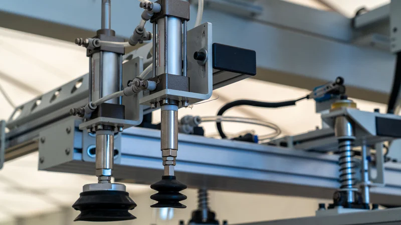
Pneumatic Actuator in an Industry
Key Takeaways
Definition - The actuator converts a source of energy, typically electric current, hydraulic fluid pressure or pneumatic pressure, into motion. It is the mechanism by which a control system acts on its environment.
Control Loop Integration - In a control loop, sensors report to a controller, and the controller sends commands to actuators such as control valves, breakers, switches and motors.
Speed vs Force - Gearing and screw pitch trade speed for force. At 24 V, the LINAK LA36 electric linear actuator moves at 135 mm/s under nominal load in its 500 N version, but at 7 mm/s in its 6,800 N version with an 8 mm spindle pitch.
Sizing Safety Margins - Festo recommends using only 50% of a pneumatic cylinder's theoretical force, and LINAK rates the LA36 for a maximum 20% duty cycle at full load on strokes up to 600 mm, at 40 °C ambient.
Motor vs Actuator - The motor is usually one component of an electric actuator. The actuator adds gear reduction, a screw where linear motion is needed, end-of-travel switches and position feedback.
Introduction
So, what is an actuator? It is the component that turns energy into motion, allowing a machine to move or control a mechanism on command. The actuators are devices powered by sources such as electric current, hydraulic fluid pressure or pneumatic pressure.
Once engineers ask, what is an actuator, the answer connects control signals with physical action. The actuators position control valves in process plants, move industrial robot joints and adjust throttle valves in car engines. They provide the movement needed to push, pull, lift, rotate or hold a load.
This guide explains what is an actuator, its operation, main types and outlines how to choose one based on force, speed, motion, control requirements and operating conditions.
What Is an Actuator? Definitions From Standards Bodies
Standards bodies describe actuators according to their role in control systems, robotics and industrial processes:
NIST: Defines an actuator as a device that moves or controls a mechanism or system. It provides a control system with the means to act on its environment, turning a control decision into physical action. [1]
IEC 60050-351, IEV 351-49-07: Defines an actuator by its position in the control chain. It takes the controlling output of the element and generates the manipulated variable needed to drive the final controlling element. [8]
ISO 8373:2021: In robotics, an actuator is a powered mechanism that converts electrical, hydraulic, pneumatic or other energy into robot motion. [6]
Emerson Control Valve Handbook: Using terminology derived from ISA 51.1, the handbook describes an actuator as a pneumatic, hydraulic or electrically powered device that supplies the force and motion needed to open or close a valve. [5]
These definitions reflect different applications. NIST emphasizes interaction with the environment, IEC specifies the control function of the actuator, ISO focuses on robot motion, and Emerson addresses valve operation. [8]
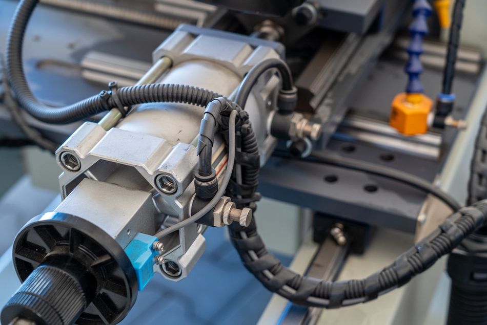
Throughout this article, actuator refers to the complete device that converts energy into mechanical motion.
How Does an Actuator Work?
The actuator takes a command, draws power from a source, and delivers force or torque over a controlled distance or angle. The control loop utilizes sensors, actuators, and controllers to manipulate a controlled process. The sensor sends measurements to the controller, which applies a control algorithm and target set points, then transmits the resulting manipulated variables to the actuators. [2]
Inside the device, an actuator typically combines four elements:
Energy Input: Electrical power, pressurized hydraulic fluid or compressed air.
Converter: Electric motor, piston or diaphragm that turns the energy into force or torque.
Transmission: Gear reduction, a lead screw, a ball screw, a rack and pinion or a lever that shapes the output into the required stroke or angle.
Feedback: Limit switches, potentiometers or Hall-effect sensors that report position to the controller.
The on-off actuator simply drives to the end of its travel, where end-stop or limit switches signal its arrival. [3][5]
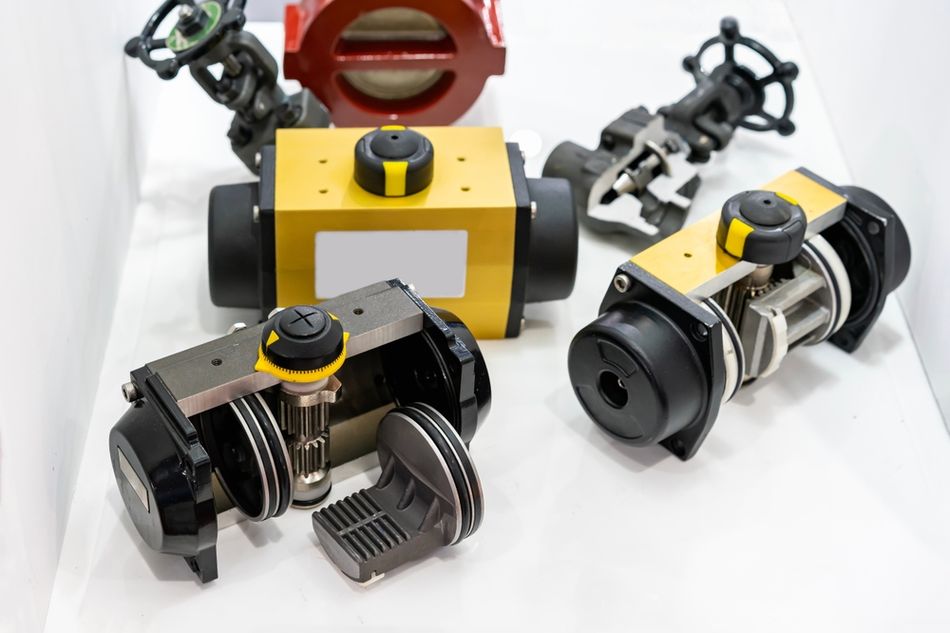
The closed-loop actuator measures its position continuously. The electronic throttle valve by Bosch comprises an electrically powered throttle valve and an angular-position sensor for position feedback. [7] The motor whose controller uses position-sensor feedback to fix the rotor angle is called a servo motor. [11]
Recommended Reading: Servo Motor: How It Works, Types, Specifications, and Sizing
Types of Actuators by Motion
The actuators produce two basic forms of output motion: linear movement along a straight path and rotary movement around an axis. This classification describes how the output moves, regardless of whether the actuator uses electrical, pneumatic or hydraulic power. For electric industrial valve actuators specifically, ISO 22153 distinguishes three types: linear, part-turn and multi-turn. [12]
Linear Actuators
The linear actuator transmits thrust to the valve for a defined linear stroke. [12] Pneumatic and hydraulic cylinders produce linear motion directly.
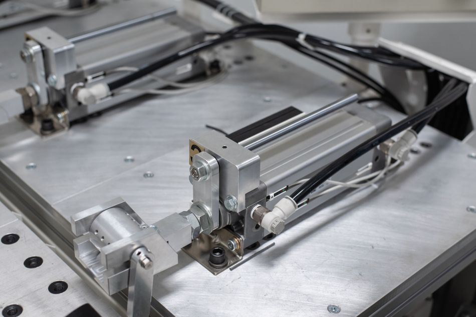
The electric linear actuator can get there with a screw: in a non-captive stepper motor linear actuator, a threaded nut molded into the hollow rotor drives a lead screw that an external guide stops from turning, so that the connection of the lead screw and threaded nut transforms the rotary motion of the rotor into the linear motion of the lead screw. [9]
Rotary Actuators
Rotary actuators apply torque to turn a shaft or load. In valve automation, their output falls into two categories:
Part-Turn Actuators: Deliver torque through less than one complete revolution. Quarter-turn operation, typically 90°, is common for ball, butterfly and plug valves. [12]
Multi-Turn Actuators: Deliver torque through at least one complete revolution. This classification describes the required rotational travel; it does not necessarily mean the actuator runs continuously. [12]
Rotary movement can also be produced from linear force. In a rack-and-pinion actuator, a moving toothed rack engages a circular pinion, turning the output shaft. The lever mechanism similarly converts linear actuator stem movement into torque. [5] The rack-and-pinion designs can introduce backlash, or lost movement when direction reverses, so their suitability for precise control depends on the complete actuator and valve assembly.
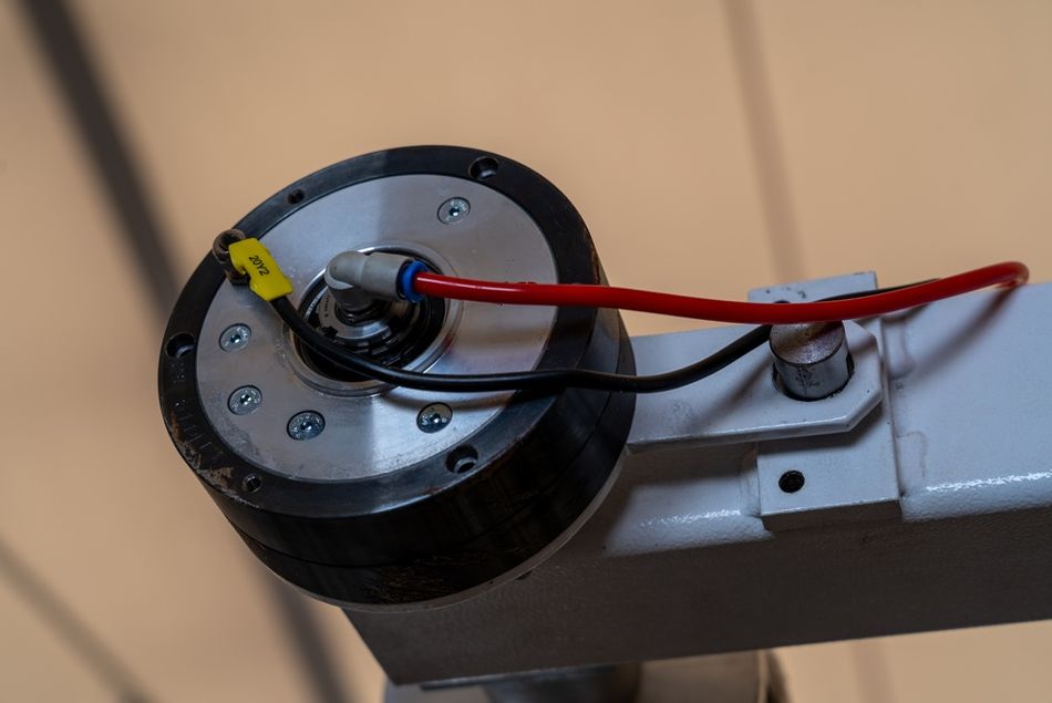
For valve mounting, ISO 5211:2026 specifies attachment flange dimensions, drive dimensions and reference interface torques for part-turn actuators, with or without gearboxes. [13] It addresses the mechanical connection rather than defining overall positioning performance.
Recommended Reading: Linear Actuator Motor: Choosing the Right Motor Technology for Modern Linear Actuators
Three Main Types of Actuators by Energy Source
The three main types of actuators are electric, hydraulic and pneumatic. Each converts supplied energy into mechanical motion, but their force, speed, control requirements and supporting equipment differ. [1][5] The energy source and motion describe separate characteristics: an actuator can, for example, be both electric and linear.
Electric Actuators
The electric actuators use electrical energy to produce motion. Motor-driven designs commonly combine a motor with gears, while linear versions often add a screw mechanism to convert rotation into thrust. In valve installations, they can be particularly useful where instrument air is unavailable, or a compressor system would be difficult to justify. [5]
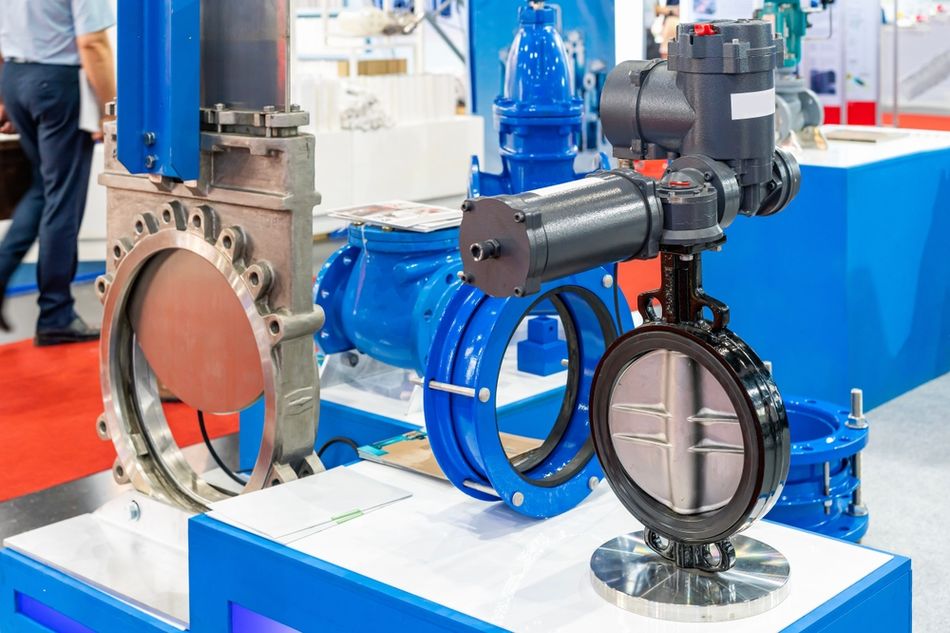
The LINAK LA36 illustrates the tradeoff between force and speed. Its specifications vary with voltage, gearing and spindle pitch, so maximum force and maximum speed should not be treated as simultaneous capabilities. Selected 24 V configurations demonstrate this relationship:
500 N Version: 160 mm/s without load and 135 mm/s at nominal load.
1,700 N Version: 72 mm/s without load and 52 mm/s at nominal load.
6,800 N Version: 17 mm/s without load and 7 mm/s at nominal load.
These are typical, configuration-specific values, with LINAK specifying ±10% variation in speed. [3] The practical lesson is to select an actuator using its speed at the required load, rather than its no-load speed.
The screw selection also affects efficiency and load holding:
Acme Screws: Typically 20–40% efficient. Their sliding friction increases the required motor input but can help resist back-driving.
Ball Screws: Typically around 90% efficient, depending on geometry. Their low friction means an external load may drive the mechanism backwards.
Roller Screws: Commonly around 85% efficient, depending on screw diameter and lead, and suited to applications requiring substantial force. [10]
The LA36 pairs its acme spindle with an integrated brake with high self-locking ability. [3]
Recommended Reading: Electric Actuator: Comprehensive Engineering Guide
Hydraulic Actuators
The hydraulic actuators use pressurized liquid to generate motion. In a hydraulic cylinder, pressure acts on a piston to extend or retract a rod. [14][15] Their ability to generate substantial force from a relatively compact cylinder makes pressure and piston area central to selection.
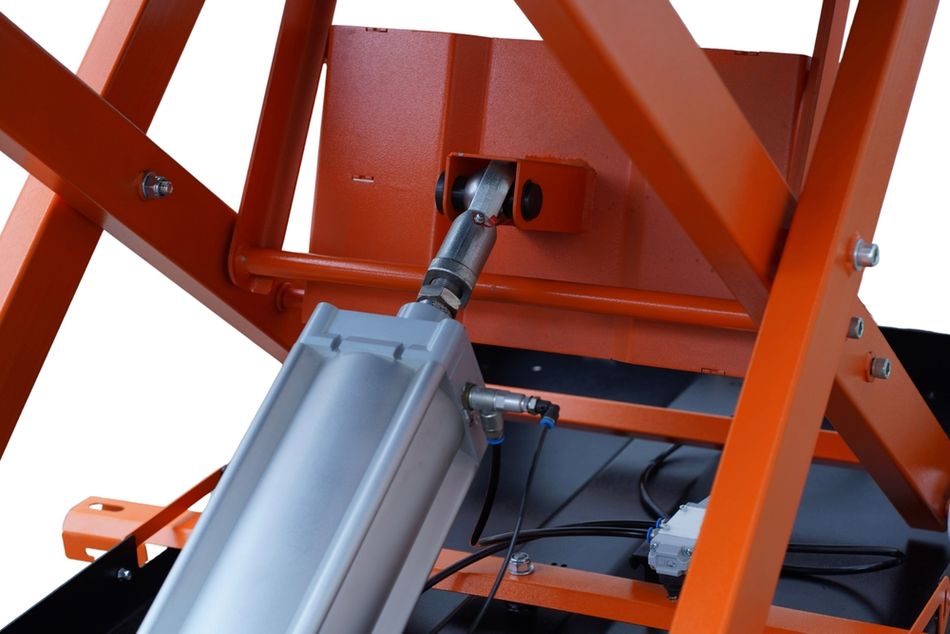
That is the core argument for hydraulic actuators. For a simplified extension calculation:
Theoretical Force = Pressure × Piston Area
ISO 6020-2 covers a 16 MPa (160 bar) cylinder series with bores from 25 to 200 mm, and since 1 MPa equals 1 N/mm², the force is easy to calculate: [14]
50 mm bore at 160 bar: 16 N/mm² × 1,963 mm² ≈ 31.4 kN
100 mm bore at 160 bar: 16 N/mm² × 7,854 mm² ≈ 125.7 kN
These are calculated theoretical forces on the full piston area, before friction. At the same 50 mm bore, 160 bar gives about 27 times the force of the 6 bar pneumatic figure below.
The price is a hydraulic system to maintain. Rexroth caps contamination in the initial fill at ISO 4406 (c) class 20/18/15, requires low-pressure operation until bleeding is complete, and calls for mounting that avoids lateral loads, bending, and buckling. [15]
Pneumatic Actuators
The pneumatic actuators use compressed air to move a piston or diaphragm. In a spring-and-diaphragm actuator, air pressure acts against a spring, and the available thrust depends on the balance between air force and spring force. Piston designs provide another way to produce linear movement or drive a mechanism that converts it into rotational motion. [5]
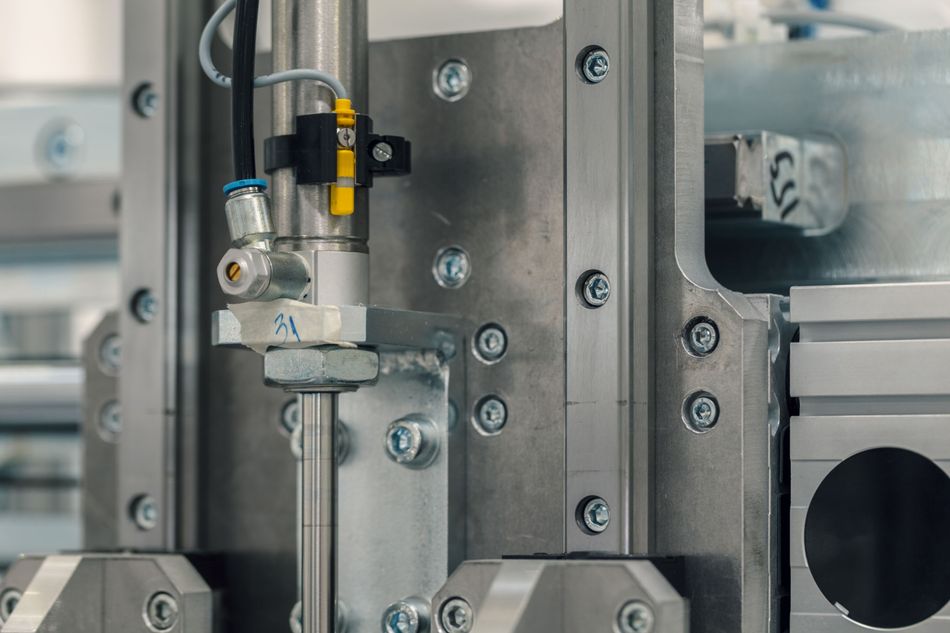
Pressure and piston area determine theoretical cylinder force. For example, DSBC cylinders by Festo provide the following advancing forces at 6 bar:
50 mm bore: Approximately 1,178 N.
100 mm bore: Approximately 4,712 N.
The 50 mm result follows directly from 0.6 N/mm² × 1,963 mm². [4] Compared with the hydraulic example at 160 bar, the same piston area produces about 27 times less theoretical force. This comparison reflects the chosen operating pressures, rather than an inherent difference in the pressure-area relationship.
Theoretical force is not the same as usable thrust: friction, opposing chamber pressure, and any return spring reduce the force available to move the load. Air quality and the manufacturer’s operating-pressure limits also need to be considered. [4][5]
For valve service, spring-return actuators can provide fail-open or fail-closed operation. When actuating pressure is lost and air can exhaust, the spring moves the valve toward its designated position. This behavior depends on the actuator, valve and control arrangement; it is not a feature of every pneumatic actuator. [5]
Recommended Reading: Pneumatic Actuators: Principles, Types and Applications
Other Actuator Types: Manual, Piezoelectric and Shape Memory Alloy
The three main families do not cover every mechanism. Other approaches serve applications with different requirements, although their classifications can overlap.
Manual Actuation: Handwheels and levers use human effort to move a mechanism. They are useful where automatic control is unnecessary and generally cost less than powered alternatives. [5]
Piezoelectric Actuation: Piezoelectric materials deform when an electric field is applied, producing very small, rapid movements. Some direct piezo actuators offer subnanometer resolution, microsecond response, and travel up to a few hundred micrometers. These are electrically powered actuators, distinguished by their conversion mechanism rather than a separate energy source.
Shape Memory Alloy Actuation: These actuators exploit temperature-driven material transformations to recover a trained shape and generate movement. NASA has developed compact rotary mechanisms using SMA elements. Heating and cooling behavior influences their operating cycle, making thermal management an important design consideration.
Recommended Reading: Powering Soft Robotics: Deeper Look at Soft Robotics Actuators
Electric vs Hydraulic vs Pneumatic Actuators
Electric, hydraulic and pneumatic actuators differ in their energy supply, force capability, feedback options and maintenance requirements.
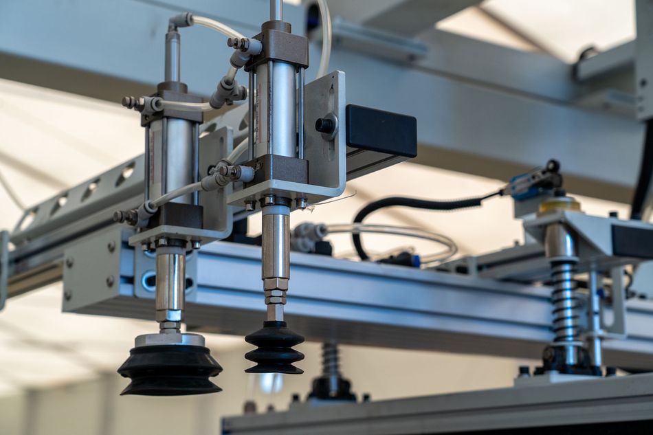
The examples below illustrate specific products and operating conditions rather than limits for each actuator family.
Electric Actuators: Use electrical power, with the LINAK LA36 available in 12, 24, 36 and 48 V DC versions. Depending on configuration, it provides rated loads from 500 to 6,800 N and optional position feedback, including Hall feedback resolutions down to 0.110 mm per count. Feedback resolution describes the measurement increment, not guaranteed positioning accuracy. Selection should account for duty cycle, speed under load and restrictions on side loading. [3]
Hydraulic Actuators: Use pressurized liquid to generate force. A 50 mm bore cylinder operating at 160 bar produces approximately 31.4 kN of theoretical extension force, before friction and opposing pressure are considered. Position measurement can be integrated into the cylinder for feedback. Fluid cleanliness, proper bleeding and mounting that avoids lateral loads are important operating considerations. [14][15]
Pneumatic Actuators: Use compressed air. At 6 bar, a Festo DSBC cylinder with a 50 mm bore produces 1,178 N of theoretical advancing force. Depending on configuration, proximity switches can detect selected positions, while compatible position sensors provide more detailed feedback. Air quality, operating pressure and sufficient force margin are important when sizing the actuator. [4]
The electric valve actuators generally have a higher initial purchase price than pneumatic alternatives. [5] However, the comparison also needs to account for the electrical supply, compressor or hydraulic power unit, associated controls and ongoing maintenance.
Key Actuator Specifications
These are the parameters to look for on an actuator datasheet, with real values from the sources above.
Force or Torque: Linear actuators deliver force, measured in newtons (N), while rotary actuators deliver torque, measured in newton metres (N·m). Distinguish the dynamic rating, which applies while moving, from the static rating, which applies while holding a load. The LINAK LA36 offers dynamic load ratings from 500 to 6,800 N, depending on configuration. [3][12]
Stroke Length or Angular Travel: Stroke is the distance a linear actuator travels between its end positions. For rotary actuators, check the available angle or number of turns. Stroke and load capacity can be linked: the cited LA36 specifications limit 6,800 N push configurations to a 600 mm stroke, while some lower-force versions allow longer travel. [3]
Speed under Load: Check operating speed at the required force or torque, rather than relying on the no-load maximum. The cited 24 V LA36 configurations provide approximately 7–135 mm/s at nominal load. Higher-force configurations generally move more slowly. [3]
Duty Cycle or Duty Class: Duty cycle defines how much an actuator can run within a specified operating period under stated conditions. The cited LA36 rating allows a maximum 20% duty cycle at full load for strokes up to 600 mm at 40 °C. Valve actuator duty classes describe the intended operating service; they should not be treated as interchangeable with a duty-cycle percentage. [3][12]
Position Feedback and Resolution: Feedback indicates actuator position, while resolution describes the smallest reported position increment. The cited LA36 Hall feedback options provide approximately 0.110–0.721 mm per count. Resolution is not the same as positioning accuracy or repeatability, so check those specifications separately when precise motion matters. [3]
Response and Travel Time: Check how the manufacturer defines timing. Response time, time to reach a percentage of the commanded movement and time to settle at the target are different measures. For example, the cited Bosch throttle valve specifies a t90 actuation time below 100 ms; that should not be described as its full settling time. [7]
Ingress Protection: An IP rating describes enclosure protection against solids and water under specified test conditions. Check whether the rating applies during movement or only when stationary. The LA36 lists IP66 during operation and IP69K when stationary. [3]
Operating Temperature: Confirm the temperature range for the complete actuator and any conditions attached to full performance. The cited LA36 full-performance range is +5 to +40 °C. A temperature limit for a particular component, such as a throttle valve’s air duct, should not be presented as the rating for the entire assembly. [3][7]
Control Interface: Check compatibility with the controller or PLC, including the required signals and communication protocol. LA36 configurations offer options such as I/O, IO-Link, CANopen, Modbus and PROFINET; availability depends on the selected version. [3]
Do not forget to check the power-off holding behavior, mounting requirements and permissible side loads. The rated thrust of an actuator alone does not establish whether it can support an unsupported load or hold position after power is removed.
How to Choose an Actuator?
Define the Motion: Linear or rotary motion, and for rotary output, part-turn or multi-turn.
Calculate the Load and Add Margin: Use F = m × g for a vertical lift, and for pneumatic cylinders use only 50% of the indicated theoretical forces. [4]
Set Stroke Length and Speed Together: Higher-force versions of an electric actuator such as the LA36 run slower. [3]
Match the Duty: Check the duty cycle, or for valve actuators, the ISO 22153 duty class: on-off (A), inching or positioning (B), modulating (C) or continuous modulating (D). [3][12]
Choose the Feedback: a limit switch provides "a discrete open or close signal" at a set position; potentiometers and Hall-effect sensors report position along the stroke. [5][3]
Define Power-Loss Behavior: ISO 22153 distinguishes "stay put" action from fail-safe action using stored electrical or mechanical energy. [12]
Check the Environment: Specify an IP rating and confirm the temperature range. [3]
Use Standard Interfaces: ISO 15552 for pneumatic cylinders, ISO 6020-2 for 160 bar hydraulic cylinders ("as required for interchangeability") and ISO 5211 for part-turn valve actuators. [4][14][13]
Worked Example: Sizing for a 55 kg Vertical Lift
The 55 kg load needs F = 55 kg × 9.81 m/s² ≈ 540 N.
Pneumatic at 6 bar: The 50% rule (Festo) calls for at least 1,080 N of theoretical force. The 40 mm bore (754 N) falls short, and the 50 mm bore (1,178 N) is the smallest that qualifies. [4]
Electric: the 1,700 N LA36 version covers 540 N with margin, at any stroke up to 1,200 mm. At 24 V, it runs 72 mm/s unloaded and 52 mm/s at nominal load, so expect a lift speed in between. At full load on strokes up to 600 mm, it is rated for 4 minutes of driving in every 20. [3]
Hydraulic at 160 bar: Even the smallest 25 mm bore in ISO 6020-2 would produce about 7.9 kN (calculated), far more than needed. Hydraulics make sense when the load itself runs to tens of kilonewtons. [14]
Actuator vs Motor: What Is the Difference?
The motor can be an actuator, but an actuator is not necessarily a motor. NIST includes motors among the actuators used in control loops, while Clemson University describes electric motors as common electromechanical actuators in vehicles. [2][11]
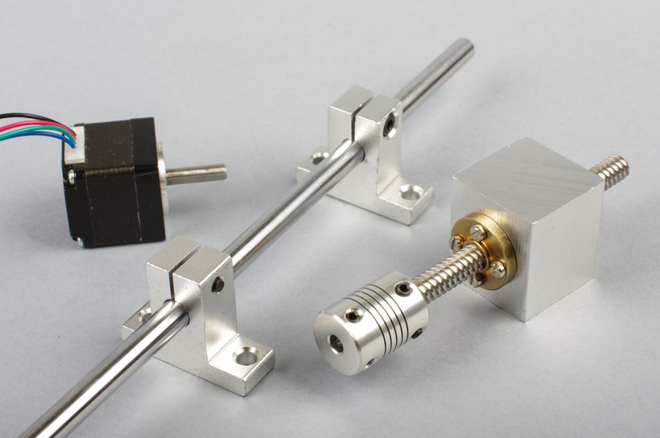
The distinction is mainly one of function and assembly. The electric motor converts electrical energy into mechanical motion, typically rotation. A motor-driven actuator combines that motor with the mechanisms needed to move a particular load. Electric valve actuators commonly include reduction gears, while an electric linear actuator may use a screw to convert rotation into thrust. [5]
For example, the LINAK LA36 combines a motor with an Acme spindle, a brake and end-stop functions, with position feedback available depending on configuration. [3] These components allow the assembly to deliver linear movement within a specified stroke. However, gearing, brakes and feedback are not universal requirements for every actuator.
Once you specify a motor, you specify the shaft speed and torque. Once you specify an actuator, you specify output force or torque, stroke or angle, duty cycle and feedback.
Recommended Reading: Actuator Motor: Differences Between Actuators and Motors, Selection, and Applications
What Does an Actuator Do in a Car?
In a car, actuators turn electronic control commands into physical movement. They operate mechanisms such as throttle valves, pumps, fans and powered positioning systems. Electric motors are a common form of automotive actuator, driving many of these functions. [11]
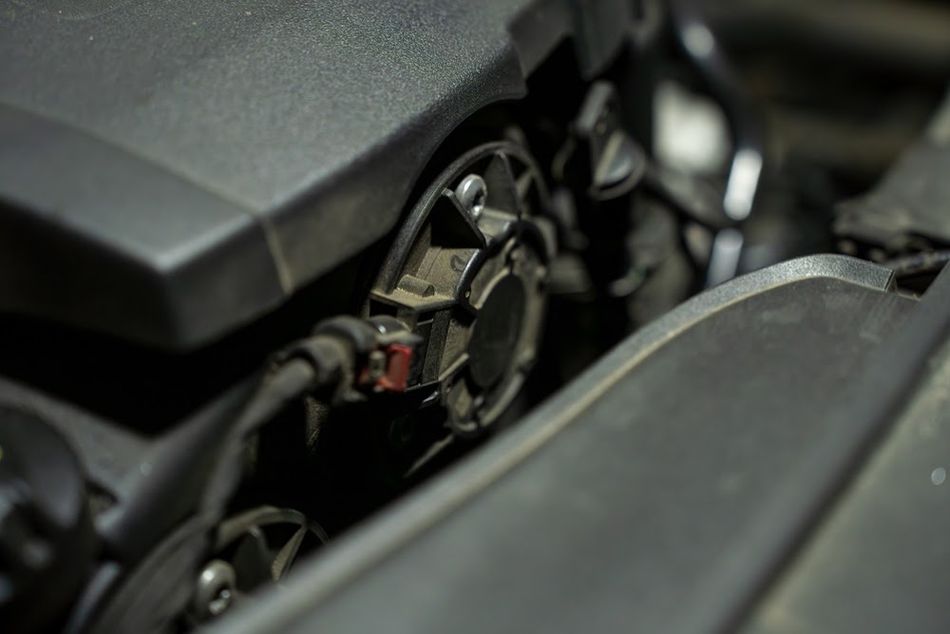
The electronic throttle valve illustrates how an actuator works within a closed-loop system. The engine control unit determines the required throttle opening using accelerator-pedal position and other torque demands. An electric motor moves the throttle plate to adjust the intake opening, while position feedback allows the controller to check and correct its movement. Bosch specifies a t90 actuation time below 100 ms for the cited throttle valve, describing how quickly it completes 90% of the commanded change. [7]
The actuator technology also extends beyond conventional motors. NASA identifies automotive door handles and hood lifts as potential applications for its shape memory alloy actuators, which generate movement through temperature-driven changes in material shape. These are proposed applications, not evidence of widespread installation in production vehicles.
Where are Actuators Used?
The actuators provide the movement needed to control equipment, position components, and automate tasks across industry and everyday life.
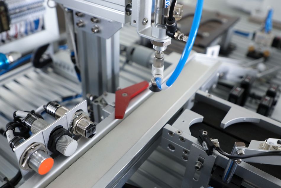
Below are the major areas where actuators are used:
Process Industries: Actuators open, close and position control valves to regulate fluid flow through pipelines and processing equipment. Pneumatic designs are widely used in control-valve applications. [5]
Industrial Automation: Actuators move machine components in response to commands from controllers such as PLCs. In automated production, they perform tasks such as pushing, clamping, lifting and positioning, while feedback helps the control system monitor the process. [2]
Robotics: Actuators move robot joints and operate mechanisms such as grippers. The robot controller coordinates these movements to carry out programmed tasks. [6]
Aerospace: Actuators move aircraft mechanisms and deploy spacecraft components. NASA identifies smart winglets, folding wing sections and solar panels as potential applications for its shape memory alloy actuator technology.
Precision Engineering: Piezoelectric actuators produce extremely small, controlled movements for precision positioning. The specialized designs can operate in ultrahigh-vacuum environments.
Home Automation and Consumer Products: Small electric actuators adjust powered furniture, operate automated blinds and move window-opening mechanisms. They turn electrical commands into convenient, repeatable movement.
Recommended Reading: Robotic Actuators: The Muscle Power of Industry 4.0
What Happens When an Actuator Goes Bad?
The failing actuator may move slowly, stop before reaching its target, operate intermittently or fail to move at all. Depending on the design, it may also lose its ability to hold position.
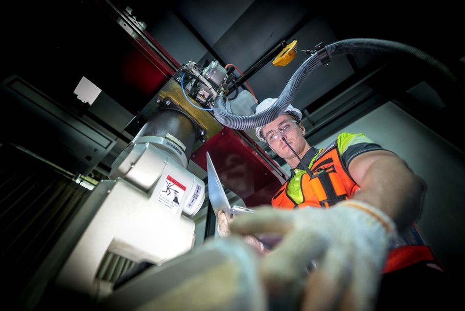
However, similar symptoms can result from a power supply problem, an incorrect control signal or a jammed mechanism, so the actuator itself is not always the cause.
Common Causes of Actuator Failure
Exceeding the Duty Cycle: Running an actuator too frequently or for too long can cause overheating. Duty-cycle limits depend on load and ambient temperature, so apply a rating stated at 40 °C with its specified operating conditions. [3]
Side Loading and Misalignment: Forces acting across the actuator’s intended direction of travel can damage or overload its mechanical components. LINAK prohibits side loading of the LA36, while Rexroth requires cylinder mounting that directs the load along the cylinder’s centreline. [3][15]
Driving into an Obstruction: The blocked load or incorrectly positioned stop can overload the drive mechanism. LINAK specifically prohibits certain standard LA36 configurations without an integrated controller or clutch from hitting a mechanical obstruction before reaching the end of their stroke. [3]
Excessive Starting and Stopping: Frequent cycling can increase motor heating and wear. The motor and actuator must be rated for the required operating pattern; motor technology alone does not remove duty-cycle limits. [5]
Contaminated Fluid or Unsuitable Air Quality: Hydraulic fluid and compressed air must meet the requirements specified for the equipment. The cleanliness and air-quality limits cited for Rexroth and Festo products are product-specific requirements, not universal limits for all actuators. [15][4]
Trapped Air and Deteriorated Seals: Hydraulic cylinders require proper bleeding before full operation. Damaged or degraded seals can cause leakage and reduce performance, while unsuitable storage conditions can contribute to seal deterioration. [15]
How to Troubleshoot an Actuator?
Work systematically from the energy supply to the driven mechanism:
Check the Supply: Confirm that the specified voltage reaches the actuator or that suitable fluid pressure is available. A supply that appears adequate at rest may drop during movement.
Check the Command: Verify that the controller or PLC is requesting movement and that the relevant operating conditions are satisfied.
Check the Feedback: Inspect position signals, limit-switch states and available fault indications. Compare the reported position with the mechanism’s actual position. [5]
Check the Mechanics: Look for binding, misalignment, side loads, obstructions or incorrectly adjusted stops. [3][15]
Before inspecting or disconnecting mechanical components, isolate the energy supply, release stored pressure and secure any load that could move. Restart only after you have identified and corrected the cause.
Conclusion
The actuator turns a controller's command and a source of energy into controlled motion. Electric actuators offer precise, programmable positioning, hydraulic actuators deliver far more force per unit of piston area than pneumatic ones, and pneumatic actuators remain the simple, economical choice where compressed air is available. Choose by motion, force with margin, stroke and speed, duty, feedback, power-loss behavior, environment and standard interfaces, and take the numbers from datasheets and standards.
Frequently Asked Questions
Q. What is an actuator in simple terms?
A. It is a device that makes something move when a controller tells it to, by converting energy into motion.
Q. What are the three main types of actuators?
A. Electric, hydraulic and pneumatic, named after their energy source. The electric actuators suit precise positioning, hydraulic actuators deliver far more force per unit of piston area than pneumatic ones, and pneumatic actuators are simple and economical where compressed air is available.
Q. What is the difference between an actuator and a motor?
A. The motor converts electric current into rotational torque, but an electric actuator builds a complete motion system around it, adding gear reduction, a screw where linear motion is needed, limit switches and position feedback.
Q. What does an actuator do in a car?
A. It turns commands from electronic control units into movement, from the electronic throttle valve that sets engine airflow to the motors behind pumps, fans and positioners.
Q. What is an example of an actuator?
A. The electronic throttle valve in a car, a pneumatic cylinder, an electric valve actuator, and the actuators in an industrial robot's joints are all examples.
Q. What happens when an actuator goes bad?
A. The function it drives stops responding correctly. Causes that manufacturers warn about include duty cycle overruns, side loads, contaminated fluid or air, and aged seals.
Q. What industries commonly use actuators?
A. Process industries, industrial automation, robotics, automotive, aerospace and precision engineering all depend on actuators.
References
[1] NIST Computer Security Resource Center. Actuator (ROS) [Cited 2026 November 15] Available at: Link
[2] NIST. Guide to Operational Technology (OT) Security [Cited 2026 November 15] Available at: Link
[3] LINAK A/S. Linear Actuator LA36 Data Sheet [Cited 2026 November 15] Available at: Link
[4] Festo. Standards-based Cylinders DSBC, to ISO 15552 [Cited 2026 November 15] Available at: Link
[5] Emerson. Control Valve Handbook, Sixth Edition [Cited 2026 November 15] Available at: Link
[6] ISO/TC 299. ISO 8373:2021, Robotics: Vocabulary [Cited 2026 November 15] Available at: Link
[7] Bosch Mobility. Electronic Throttle Valve [Cited 2026 November 15] Available at: Link
[8] Electropedia. IEV 351-49-07: Actuator [Cited 2026 November 15] Available at: Link
[9] Nanotec Electronic. LA: Non-Captive Linear Actuators [Cited 2026 November 15] Available at: Link
[10] Tolomatic. Selecting the Optimal Screw Technology [Cited 2026 November 15] Available at: Link
[11] Clemson University. Electric Motors in Automobiles [Cited 2026 November 15] Available at: Link
[12] CDN. ISO 22153:2020, Electric Actuators for Industrial Valves [Cited 2026 November 15] Available at: Link
[13] ISO. ISO 5211:2026, Industrial Valves: Part-Turn Actuator Attachments [Cited 2026 November 15] Available at: Link
[14] CDN. ISO 6020-2:2015, Hydraulic Fluid Power: Mounting Dimensions for Single Rod Cylinders [Cited 2026 November 15] Available at: Link
[15] Bosch Rexroth AG. Hydraulic Cylinders, Mill Type and Tie Rod Design: Operating Instructions, RE 07100-B [Cited 2026 November 15] Available at: Link
in this article
1. Key Takeaways2. Introduction3. What Is an Actuator? Definitions From Standards Bodies4. How Does an Actuator Work?5. Types of Actuators by Motion6. Three Main Types of Actuators by Energy Source7. Electric vs Hydraulic vs Pneumatic Actuators8. Key Actuator Specifications9. How to Choose an Actuator?10. Actuator vs Motor: What Is the Difference?11. What Does an Actuator Do in a Car?12. Where are Actuators Used?13. What Happens When an Actuator Goes Bad?14. Conclusion15. Frequently Asked Questions16. References