Types of PCB Connectors: An In-Depth Guide
The world of PCB connectors is diverse and expansive, catering to various applications in the field of electronics. In this article, we’ll dive and explore from the basics of board-to-board and wire-to-board connector types, to specialty connectors designed for specific use cases.

24 Jan, 2024. 21 minutes read
Introduction
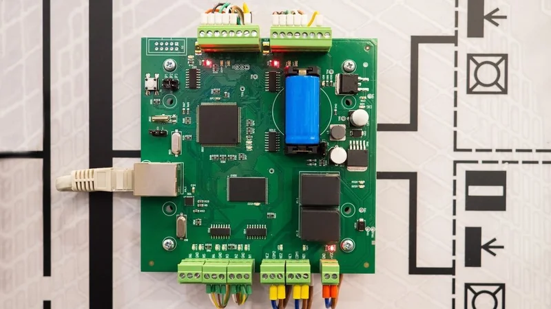
Printed Circuit Board (PCB) connectors are fundamental components in the realm of electronic design. They serve as critical interfaces that facilitate communication between different parts of an electronic system. PCB connectors are designed to transmit signals or power from one PCB board to another, or to transfer them from a PCB to another device within the system.
By using connectors, manufacturers can easily assemble, repair, or upgrade different parts of an electronic system. This flexibility is crucial in today's rapidly evolving technological landscape, where adaptability reduces costs and time-to-market for new products.Their role is pivotal in ensuring the smooth and efficient operation of electronic devices.
Each type of connector comes with its unique set of characteristics and specifications, like different pin header connector counts, orientations (straight or right-angle), and locking mechanisms, making it suitable for certain applications. This variety allows for flexibility in electronic design, enabling designers to choose connectors that best meet their project requirements. Overall, PCB connectors are irreplaceable in the electronics industry, enabling the construction of a myriad of electronic devices that are central to modern life.
Understanding PCB Connectors
PCB connectors are integral components in electronic circuits. They are designed to establish and maintain a reliable interconnect between different parts of an electronic system. This connection can be between two PCBs within the same device, between a PCB and external devices, or between a PCB and the wires that connect to other components.
The basic structure of a PCB connector includes several key elements. The housing, often made of plastic, provides mechanical support and ensures correct alignment of the connector. The contacts, usually made of a conductive metal, are responsible for the actual electrical connection. Depending on the design, a PCB connector may also include other components such as locking mechanisms for secure connection, and seals for protection against environmental factors.
Choosing the right type of connector is crucial in electronic design. The choice of connector influences the performance, reliability, and cost of the electronic device. For instance, a connector with low contact resistance and high insulation resistance results in efficient signal transmission, while a robust and durable connector enhances the device's reliability. Therefore, understanding the characteristics and capabilities of different types of PCB connectors is essential for making an informed selection.
The Function of PCB Connectors
PCB connectors serve several primary functions in electronic circuits. One of the most important is signal transmission. Connectors enable the flow of electrical signals between different parts of an electronic system, ensuring that the system operates as intended. For example, in a computer, connectors transmit data signals between the motherboard and peripheral devices such as the hard drive and keyboard.
Another key function of PCB connectors is power distribution. Connectors are used to deliver power from the power source to various components on the PCB. For instance, in a smartphone, connectors distribute power from the battery to the processor, display, and other components.
PCB connectors also contribute to the modularity of electronic devices. They allow components to be easily added, removed, or replaced, facilitating upgrades and repairs. For example, in a modular synthesizer, connectors enable individual modules to be rearranged or replaced, allowing musicians to customize the instrument according to their needs.
PCB connectors are used in a wide range of electronic devices. In a laptop, for instance, connectors are used to link the motherboard with the display, keyboard, and trackpad, as well as with external devices such as USB drives and power adapters. In a car, connectors enable communication between the engine control unit and various sensors and actuators. In a satellite, connectors are used to connect the onboard computer with the communication equipment, power supply, and scientific instruments. These examples illustrate the versatility and importance of PCB connectors in modern electronics.
Types of PCB Connector Mounting
PCB connectors can be mounted on the board in different ways, each with its own set of characteristics and considerations. The two primary methods of mounting are through-hole mounting and surface mount technology (SMT).
Through-hole mounting involves inserting the leads of the connector into pre-drilled holes on the PCB. The leads are then soldered to pads on the opposite side of the board. This method provides a strong mechanical bond between the connector and the board, making it suitable for connectors that will be subjected to physical stress. However, through-hole mounting requires drilling holes into the PCB, which can increase manufacturing costs and limit the available space for routing traces on the board.
Surface mount technology (SMT), on the other hand, involves soldering the connector directly onto the surface of the PCB. This method allows for smaller connectors and higher density layouts, as it eliminates the need for drilling holes into the board. SMT also enables faster and more automated assembly processes, which can reduce manufacturing costs. However, surface-mounted connectors may not be as mechanically robust as through-hole mounted connectors, and they may require more careful design to ensure reliable electrical connections.
The choice of mounting [1] method can significantly impact the design and manufacturing of PCBs. For instance, through-hole mounting may be preferred for heavy-duty connectors in industrial equipment, where mechanical strength is a priority. On the other hand, surface mount technology may be the preferred choice for compact, high-speed electronic devices such as smartphones and laptops, where space is at a premium and high-density layouts are required. Therefore, designers must carefully consider the requirements of their specific application when choosing the mounting method for their PCB connectors.
Suggested Reading: Through Hole vs Surface Mount: Unveiling the Optimal PCB Assembly Technique
Categories of PCB Connectors
PCB connectors can be broadly categorized into several main types based on their application. These categories include board-to-board connectors, wire-to-board connectors, and input/output connectors, among others. Each category serves a specific purpose in electronic design and has its unique set of characteristics.
The categorization of PCB connectors is primarily based on their function and the type of connection they establish. For instance, board-to-board connectors are used to link two PCBs together, while wire-to-board connectors connect wires to a PCB. The specific requirements of the electronic device, such as the need for data transmission or power supply, also play a role in determining the appropriate category of connector.
This section will delve into the main categories of PCB connectors, providing an overview of their characteristics, types, and use cases. It will also discuss the considerations for selecting connectors within each category, helping readers make informed decisions in their electronic design projects.
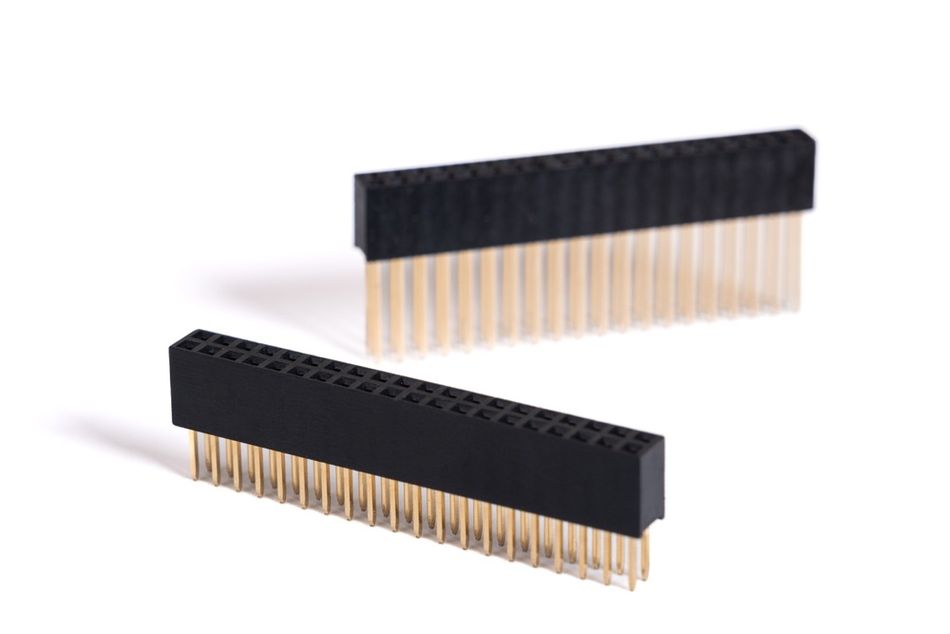
Board-to-Board Connectors
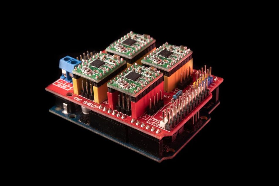
Board-to-board connectors, including backplane connectors, are designed to establish an interconnect between two PCBs. They are commonly used in electronic devices where multiple boards need to communicate with each other. For instance, in a computer, board-to-board connectors might link the motherboard with a daughterboard that provides additional functionality, while backplane connectors are often utilized in larger systems to connect several boards to a central backplane.
When selecting a board-to-board connector, several factors need to be considered.
One of the key considerations is the spacing between the boards, which determines the height of the connector. The alignment of the boards is another important factor, as it affects the orientation of the connector. Other considerations include the number of contacts needed, the current rating of the connector, and the environmental conditions the connector will be exposed to.
By carefully considering these factors [2], designers can select the most suitable board-to-board connector for their specific application.
Suggested Reading: What is a Multilayer PCB?
Wire-to-Board Connectors
Wire-to-board connectors are used to connect wires to a PCB. They are essential in electronic devices where external components, such as sensors or actuators, need to be connected to the board. These connectors provide a flexible and reliable connection, allowing for easy assembly and disassembly of the device.

There are several common types of board-to-wire connectors, each with its unique characteristics. Crimp connectors, for instance, involve crimping a metal contact onto the wire, which is then inserted into a plastic housing that can be plugged into a receptacle on the board. This type of connector is known for its durability and reliability, making it suitable for applications where a strong and stable connection is required.
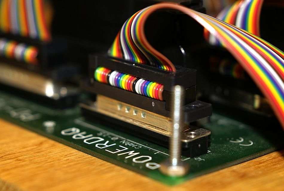
Insulation Displacement Connectors (IDC) are another type of wire-to-board connector. They work by displacing the insulation of the wire to establish a connection with the conductor. IDC connectors are quick and easy to install, as they do not require stripping the wire insulation or soldering. However, they may not be as robust as crimp connectors, especially in high-vibration environments.
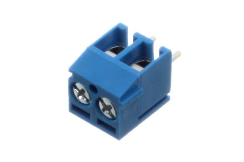
Terminal block connectors, on the other hand, use a screw or spring mechanism to secure the wire to the connector. They are commonly used in applications where field wiring is required, as they allow for easy and tool-free wire installation and removal.
When choosing a wire-to-board connector, several factors need to be considered. The wire gauge, or diameter, is one of the key considerations, as it determines the size and type of connector that can be used. The current rating of the connector is another important factor, as it must be able to safely carry the electrical current required by the device. Other considerations include the number of contacts needed, the pitch (distance between contacts), and the environmental conditions the connector will be exposed to. By taking these factors into account, designers can select the most suitable wire-to-board connector for their specific application.
Input/Output Connectors
Input/Output (I/O) connectors are PCB connector types that facilitate the communication between an electronic device and the external world. They are the interfaces through which data or power enters or exits a device. I/O connectors are critical in enabling the functionality of a wide range of devices, from computers and smartphones to industrial machinery and medical equipment.
There are numerous types of I/O connectors, each designed for a specific purpose or standard. USB connectors (Universal Serial Bus) , for instance, are widely used for data transfer and power supply in a variety of devices, including computers, smartphones, and peripheral devices.
HDMI (High-Definition Multimedia Interface) connectors are used to transmit high-definition audio and video signals, typically between a device like a computer or game console and a display monitor or television.

Ethernet connectors, often in the form of RJ45 plugs and sockets, are used for wired network connections, enabling high-speed data transfer between devices in a local area network.
The role of I/O connectors in interfacing with other devices and systems is crucial. They enable the transfer of data and power between devices, allowing them to interact and function together as part of a larger system. For example, in a computer system, I/O connectors allow the computer to interact with peripheral devices such as printers, scanners, and external storage devices. In an industrial automation system, I/O connectors enable communication between control systems and machinery, allowing for automated control of manufacturing processes. Therefore, the selection of appropriate I/O connectors is a critical aspect of electronic design, impacting the functionality, compatibility, and performance of the device.
Specialty PCB Connectors
Specialty PCB connectors are designed for specific applications that require unique properties not typically found in standard connectors. These connectors often have to meet stringent requirements due to the environments they operate in or the specialized functions they perform. For example, certain applications may demand connectors that can handle very high frequencies or that can withstand extreme environmental conditions. The below sections discuss the variety of these specialty PCB connectors.
High-Frequency PCB Connectors
High-frequency connectors [3] are a type of specialty connector designed to maintain signal integrity at microwave and radio frequencies. These connectors are engineered to minimize signal loss and reflection, which can degrade performance in high-frequency applications. They are characterized by their precision-engineered construction and materials that provide consistent impedance, low insertion loss, and high return loss. The design of these connectors often includes features such as air dielectrics, tight-tolerance center conductors, and advanced shielding techniques to achieve the desired performance.
High-frequency PCB connectors are engineered to operate effectively at frequencies typically ranging from the upper MHz to several GHz. These connectors are crucial in applications such as telecommunications, satellite communication, and high-speed data transmission, where maintaining signal integrity at high frequencies is essential.
Impedance matching [4] is a critical aspect of high-frequency connector design. To prevent signal reflections, which can cause power loss and signal degradation, the impedance of the connector must match the impedance of the circuit (usually 50 or 75 ohms). High-frequency connectors are designed with precise geometries and materials to ensure a consistent impedance match along the signal path.
Applications that require high-frequency connectors include wireless communication systems, where they are used to connect antennas to transceivers, and in test and measurement equipment, where they provide the necessary precision and reliability for accurate high-frequency measurements. In these applications, the performance of the high-frequency connector directly impacts the overall system performance, making the choice of connector a critical design decision.
Power Connectors
Power connectors in PCB design are crucial for delivering the necessary electrical power to operate the circuitry on the board. They are specifically designed to handle higher currents and voltages than signal connectors, ensuring that power is supplied safely and reliably to the components that require it. These connectors must be capable of withstanding the thermal and electrical stresses associated with power transmission.
The features of power connectors are varied and are chosen based on the requirements of the application [5][6]. Some common types of power connectors are - AC Power Connectors, DC Power Connectors, IEC Connectors, Automotive Power Connectors, DIN Connectors, MC4 Connectors.
Current carrying capacity, or the amount of current that can flow through the connector without causing excessive heat or damage, is a primary consideration. This is often measured in amperes (A) and is dependent on the connector's material and design.
Voltage rating is another critical feature, indicating the maximum voltage the connector can handle. This is particularly important in applications with high power requirements, as using a connector with an insufficient voltage rating can lead to electrical arcing and potential failure.
Selecting the appropriate power connector for a given application involves considering several factors.
The current and voltage requirements of the circuit must be matched with the connector's specifications. The operating environment is also a consideration; connectors used in high-temperature or corrosive environments may need additional features such as enhanced insulation or corrosion-resistant materials.
Additionally, the physical size and shape of the connector must fit within the spatial constraints of the PCB layout. By carefully evaluating these factors, designers can ensure that the chosen power connector will provide reliable and efficient power distribution in their electronic device.
FFC/FPC Connectors
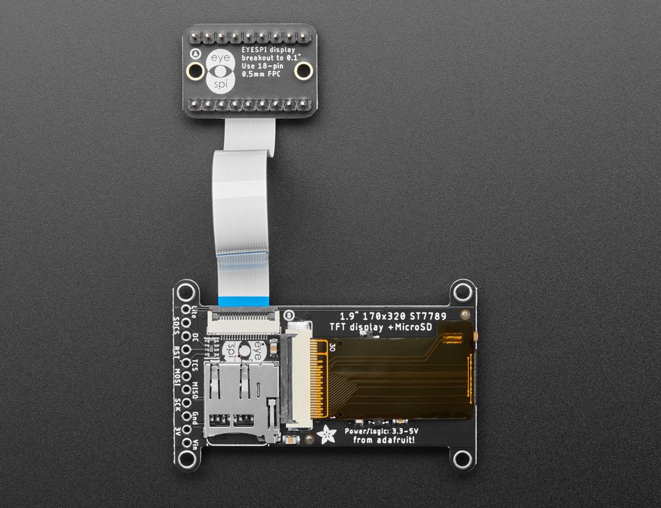
FPC (Flexible Printed Circuit) and FFC (Flexible Flat Cable) connectors are specialized types of connectors designed for use with flexible electronic components. FPC connectors are used to connect flexible printed circuit boards, which are thin, flexible PCBs. FFC connectors, on the other hand, are used for connecting flat flexible cables, which are ribbon-like, extremely thin, and flexible.
Flexible Printed Circuit and Flexible Flat Cable connectors stand out for their unique set of features, tailored to meet the demands of modern electronic design. These features include:
- Flexibility: Their remarkable flexibility allows them to bend and conform to tight spaces or curved surfaces. This makes them ideal for innovative designs in foldable or wearable electronics, where rigid connectors would be impractical or inefficient.
- Low Profile: Their thin and compact design is a crucial advantage in space-constrained applications. FPC/FFC connectors' low profile enables sleeker, more streamlined electronic devices by minimizing the space required for connections, essential in modern, miniaturized gadgets like smartphones and tablets.
- High-Density Connections: FPC/FFC connectors excel in providing high-density connections in a minimal footprint. This feature is particularly beneficial in complex electronic assemblies, allowing for a larger number of connections per unit area, which is vital in sophisticated, multi-functional devices.
- Ease of Installation: The design of FPC/FFC connectors simplifies assembly processes, offering quick and straightforward installation without the need for soldering. This user-friendly feature not only speeds up manufacturing but also reduces the likelihood of errors during assembly, enhancing overall production efficiency.
FPC/FFC connectors are particularly beneficial in applications where space is limited and flexibility is required. They are ideal for compact electronic devices where the internal components need to be connected in a tight space or require bending and folding during use or installation. Their slim and flexible nature allows for easier routing of connections in complex electronic assemblies.
Rugged and Waterproof Connectors
Rugged and waterproof connectors are designed to withstand harsh environmental conditions. These connectors are built to resist factors such as moisture, dust, extreme temperatures, and physical impacts. The ruggedness of a connector refers to its ability to endure mechanical stress, such as vibration, shock, and physical impact, without failure. Waterproof connectors, on the other hand, are designed to prevent the ingress of water, allowing them to function reliably in wet or submerged conditions.
In environments where electronics are exposed to moisture, dust, chemicals, or physical impacts, waterproof or rugged connectors are used. These connectors are built to be robust with features like heavy-duty seals, reinforced housings, and locking mechanisms that prevent ingress of contaminants and ensure the connector remains intact even under physical stress.
Rugged and waterproof connectors are often associated with specific standards and certifications that attest to their performance under harsh conditions. For instance, the IP (Ingress Protection) rating system is commonly used to classify the degree of protection provided against the intrusion of solid objects (including body parts like hands and fingers), dust, accidental contact, and water in electrical enclosures. An IP rating consists of two numbers: the first number indicates the level of protection against solids, and the second number indicates the level of protection against liquids. For example, a connector with an IP67 rating is dust-tight and can withstand temporary immersion in water [7].
Rugged and waterproof connectors are necessary in a variety of environments where standard connectors would fail. For instance, in outdoor telecommunications equipment, connectors must be able to withstand exposure to rain, snow, and temperature extremes. In marine applications, connectors must be resistant to salt water, which is highly corrosive. In industrial settings, connectors may need to endure exposure to dust, chemicals, and mechanical vibration or impact. In all these cases, the use of rugged and waterproof connectors can ensure reliable operation and longevity of the electronic equipment.
Connector Selection Criteria
Selecting the right PCB connector is a critical aspect of electronic design, as the choice can significantly impact the performance, reliability, and cost of the device. There are several key factors to consider when selecting a PCB connector.
The size of the connector must be appropriate for the available space on the PCB and the device enclosure. The connector's mechanical design, including its locking mechanisms, should ensure a secure and reliable connection. Some connectors use friction to hold the mating parts together, while others may use latching or screw mechanisms for a more secure connection.
Electrical Specifications
The electrical parameters [8] of a connector play a significant role in its selection. These include voltage rating, current rating, contact resistance, and signal integrity.
- Current Rating: It is the maximum current that the connector can safely carry without exceeding its temperature limits. This is determined by factors such as the contact material, the size of the contact, and the connector's overall thermal design.
- Voltage Rating: It is the maximum voltage that the connector can safely handle. Exceeding this rating can lead to electrical breakdown and failure. The voltage rating is determined by factors such as the insulation material and the spacing between contacts.
- Signal Integrity: Signal integrity is another important factor. In high-speed data applications, for instance, the connector must be able to transmit signals without significant distortion or loss. This requires careful consideration of the connector's impedance, crosstalk, and other electrical characteristics.
- Contact resistance: It refers to the resistance encountered by the electrical current at the point of contact between the connector's mating parts. Lower contact resistance typically results in less power loss and heat generation, contributing to better overall performance.
- Derating: Derating involves operating a connector below its maximum rated electrical or thermal capacity to enhance reliability and longevity. For example, a connector with a current rating of 5A might be derated to operate at only 4A in a particular application. This provides a safety margin and helps to account for factors such as variations in operating conditions and manufacturing tolerances.
Mechanical considerations play a significant role in the selection of a PCB connector. Below are some of the essential mechanical factors:
- Mating Cycles: It refers to the number of times a connector can be connected and disconnected without significant degradation in performance. This is particularly important in applications where connectors are frequently plugged and unplugged.
- Housing Material: The housing material can impact the connector's durability, weight, and resistance to environmental factors such as temperature, humidity, and corrosive substances. Common materials include plastics for their versatility and cost-effectiveness, and metals for their strength and durability. The choice of material can also affect the connector's electrical properties, such as its insulation and shielding effectiveness.
- Connector Geometry: Connector geometry including its size, shape, and pin configuration, can significantly impact PCB layout and design. The connector must fit within the available space on the PCB and within the device enclosure. The pin configuration, or the arrangement of the connector's contacts, can affect how the connector interfaces with the circuitry on the PCB. For example, some connectors are designed to minimize the length of the signal paths, which can help to maintain signal integrity in high-speed applications. The geometry of the connector can also influence its ease of use, such as how easily it can be plugged and unplugged, and its compatibility with other components and systems.
Environmental and Compliance Factors
The following environmental factors can significantly influence the selection of a PCB connector.
- Operating Temperature Range: The operating temperature range is a key consideration, as connectors must be able to function reliably under the specific temperature conditions of their application. For instance, connectors used in industrial or outdoor applications may need to withstand extreme temperatures, while those used in controlled environments such as data centers may not.
- Exposure: Exposure to chemicals is another environmental factor. In certain industries, connectors may come into contact with corrosive substances, requiring the use of materials that can resist chemical degradation.
- Compliance: Compliance with industry standards is another critical factor in connector selection. Standards such as RoHS (Restriction of Hazardous Substances) and REACH (Registration, Evaluation, Authorization, and Restriction of Chemicals) regulate the use of certain hazardous substances in electronic equipment. RoHS, for example, restricts the use of specific hazardous materials found in electrical and electronic products, including lead, mercury, and cadmium. REACH, on the other hand, aims to improve the protection of human health and the environment from the risks posed by chemicals.
Environmental and compliance factors can limit or dictate connector options. For instance, a connector that meets the required electrical and mechanical specifications but does not comply with RoHS would not be suitable for use in a product that is to be sold in the European Union. Similarly, a connector that is not rated for the operating temperature range or chemical exposure of its intended application would not be a viable choice, regardless of its other attributes. Therefore, understanding these factors [8] and how they impact connector selection is crucial for the successful design and operation of electronic devices.
Innovations in PCB Connector Technology
Recent advancements in PCB connector technology have been driven by the evolving needs of modern electronic devices. Innovations in materials and manufacturing processes are also playing a significant role in connector design.
For instance, the use of high-performance plastics and advanced metal alloys can enhance the electrical and mechanical performance of connectors, while also reducing their weight and cost. New manufacturing techniques, such as micro-molding and high-precision stamping, are enabling the production of connectors with complex geometries and high dimensional accuracy. Let’s explore a few of the innovations below.
Miniaturization of Connectors
One of the most notable trends is the move towards miniaturization and higher density connectors. As electronic devices become smaller and more powerful, there is a growing demand for connectors that can support high-speed data transmission while occupying minimal space on the PCB. This has led to the development of connectors with smaller pitches, the distance between the center of one contact to the center of the next, allowing for more contacts to be packed into a smaller area.
Connector Miniaturization Challenges
For instance, as connectors become smaller, the mechanical and electrical tolerances become more critical, requiring more precise manufacturing processes.
Additionally, smaller connectors must still meet the same performance and reliability requirements as their larger counterparts.
Connector Miniaturization Solutions
For example, high-density array connectors can provide a large number of contacts in a small footprint, enabling high-speed data transmission in compact devices. Advanced materials and coatings can enhance the electrical and mechanical performance of miniaturized connectors, while innovative design features, such as integrated locking mechanisms, can ensure a reliable connection despite the small size.
Connector Miniaturization Applications.
In mobile devices, for instance, space is at a premium, and small connectors can help to maximize the available space for other components.
In high-speed data applications, such as servers and networking equipment, miniaturized high-density connectors can support the transmission of large amounts of data in a compact space.
In medical devices, small connectors can enable the design of compact and portable devices, improving patient comfort and mobility.
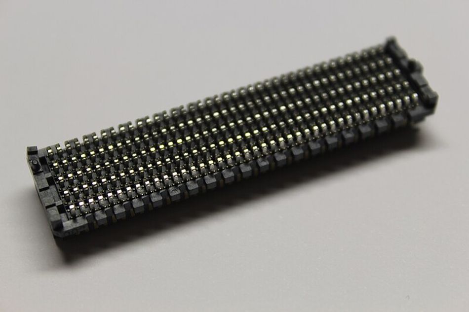
High-Density Connectors
High-density connectors are a type of connector that provides a large number of contacts within a small footprint. These connectors are designed to maximize the use of space on a PCB, enabling the transmission of more signals or power lines in a given area.
High-density Connectors Advantages
They can support high-speed data transmission, making them suitable for applications such as servers, networking equipment, and high-performance computing. They also allow for more compact and lightweight device designs, which can be beneficial in portable and handheld devices.
High-density Connectors Considerations
One of these is signal crosstalk, which is the interference caused by the electromagnetic fields of adjacent signals. As the contacts in a high-density connector are closely packed, managing crosstalk is crucial to maintain signal integrity.
Techniques such as shielding, differential signaling, and careful routing can be used to mitigate crosstalk.
Thermal management is another important consideration. As more contacts are packed into a smaller area, the connector can generate more heat, which needs to be effectively dissipated to prevent overheating and ensure reliable operation.
High-density Connectors Applications
In data centers, for instance, high-density connectors enable the design of compact and high-performance servers and storage systems. These connectors can support the high-speed data transmission required in these applications, while also saving space and reducing weight.
In the aerospace industry, high-density connectors are used in avionics systems, where they enable the transmission of large amounts of data in a compact space, while also withstanding the harsh environmental conditions of flight.
In medical devices, high-density connectors can enable the design of compact and portable devices, improving patient comfort and mobility.
Material and Manufacturing Innovations
New materials are being introduced in the manufacturing of connectors to enhance their performance and reliability. For instance, high-performance plastics such as PEEK (Polyether ether ketone) and LCP (Liquid Crystal Polymer) are being used for their excellent electrical insulation properties, high-temperature resistance, and chemical stability. These materials can withstand the harsh conditions of soldering processes and are suitable for high-frequency applications. Advanced metal alloys are also being used for contacts to improve conductivity, corrosion resistance, and durability.
Manufacturing innovations are leading to more reliable and cost-effective connectors. Techniques such as micro-molding and high-precision stamping are enabling the production of connectors with complex geometries and high dimensional accuracy. These techniques can produce connectors with smaller pitches and higher contact densities, supporting the trend towards miniaturization. Automated assembly processes are also being adopted to increase production efficiency and reduce manufacturing costs. These processes can ensure consistent quality and reduce the risk of human error.
The environmental impact of these innovations is also noteworthy. The use of environmentally friendly materials and manufacturing processes is becoming increasingly important in the electronics industry. For instance, the use of lead-free solder and RoHS-compliant materials can reduce the environmental impact of connector manufacturing. Additionally, manufacturing processes that reduce waste and energy consumption can contribute to sustainability. For example, the use of additive manufacturing or 3D printing can produce connectors with less material waste compared to traditional manufacturing methods.
Conclusion
In conclusion, the world of PCB connectors is a fascinating and crucial domain within electronic design, playing an integral role in the functionality and reliability of myriad electronic devices. From basic board-to-board and wire-to-board connectors to highly specialized options like high-frequency and rugged connectors, the range and versatility of PCB connectors are immense. Whether in a smartphone, a satellite, or industrial machinery, PCB connectors are indispensable, quietly underpinning the functionality of devices that are central to modern life. As technology advances, the importance of understanding and selecting the right connectors remains a critical aspect of electronic design, ensuring the seamless operation and longevity of electronic devices.
FAQs
1. What is a high-density connector?
A high-density connector is a type of connector that provides a large number of contacts within a small footprint. These connectors are designed to maximize the use of space on a PCB, enabling the transmission of more signals or power lines in a given area.
2. What are the challenges associated with miniaturized connectors?
As connectors become smaller, the mechanical and electrical tolerances become more critical, requiring more precise manufacturing processes. Additionally, smaller connectors must still meet the same performance and reliability requirements as their larger counterparts.
3. How do environmental factors affect connector selection?
Environmental factors such as operating temperature range and exposure to chemicals can significantly influence the selection of a PCB connector. Connectors must be able to function reliably under the specific environmental conditions of their application.
4. Why is compliance with industry standards important in connector selection?
Compliance with industry standards such as RoHS and REACH is important as these standards regulate the use of certain hazardous substances in electronic equipment. A connector that does not comply with these standards would not be suitable for use in a product that is to be sold in regions where these standards apply.
5. How are innovations in materials and manufacturing processes impacting connector design?
Innovations in materials and manufacturing processes are enhancing the performance and reliability of connectors. For instance, the use of high-performance plastics and advanced metal alloys can improve the electrical and mechanical performance of connectors. New manufacturing techniques are enabling the production of connectors with complex geometries and high dimensional accuracy.
References
[1] Matric. Through-hole vs. surface mount. Link
[2] Octopart. Selecting Board-to-Board Connectors. Link
[3] Allion. Understanding High Frequency Connectors. Link
[4] Panasonic. Impedance and Connector. Link
[5] Bravoelectro. Power Supply Connector Types. Link
[6] Uk.rs-online. Power Connector types and features. Link
[7] Norcomp. What is IP67? (and its importance). Link
[8] Sunkye. The guide for selecting electrical connectors. Link
in this article
1. Introduction2. Understanding PCB Connectors3. The Function of PCB Connectors4. Types of PCB Connector Mounting5. Specialty PCB Connectors6. Connector Selection Criteria7. Environmental and Compliance Factors8. Innovations in PCB Connector Technology9. Conclusion10. FAQs11. References