Through Hole vs Surface Mount: Unveiling the Optimal PCB Assembly Technique
Two primary PCB assembly techniques have emerged as the electronics industry standards: Through-Hole Technology (THT) and Surface Mount Technology (SMT). This article delves into the intricacies of THT and SMT, providing a thorough comparison of their advantages, disadvantages, and applications.

06 Dec, 2023. 15 minutes read
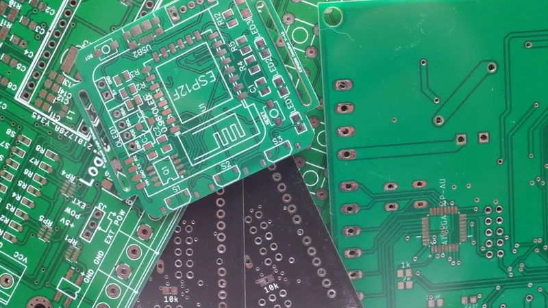
Surface Mounted Components Close up
Introduction to PCB Assembly Techniques
Printed Circuit Board (PCB) assembly is a cornerstone of the electronics manufacturing industry. It involves the intricate placement of electronic components onto a PCB to create a fully functional printed circuit assembly (PCA), also known as a printed circuit board assembly (PCBA). This intricate process requires a high degree of precision and technical expertise.
The PCB assembly journey begins with the design of the PCB layout, carefully mapping out the placement of each component. This meticulously crafted layout is then transferred onto a physical board, creating a 'printed' circuit board. The electronic components are then mounted onto the PCB using two primary methods: Surface Mount Technology (SMT) and Through-Hole Technology (THT).
Choosing the right assembly technique is crucial as it directly influences the performance, durability, and cost-effectiveness of the final product. Factors such as circuit complexity, component type, application requirements, and production volume all play a role in determining the most suitable assembly method.
In the following sections, we will delve deeper into two of the most commonly used PCB assembly techniques - Through Hole Technology (THT) and Surface Mount Technology (SMT), comparing their processes, advantages, disadvantages, and applications.
Understanding Through Hole Technology
Through Hole Technology (THT) is one of the oldest methods used in printed circuit board assembly. Despite the advent of newer technologies, THT remains a popular choice for certain applications due to its robustness and high reliability.
The Concept of Through Hole Technology
Through-hole technology involves the use of leads on the through-hole components that are inserted into holes drilled into the PCB and soldered to pads on the opposite side. These leads are either manually inserted or done by automated machines. The soldering process can be performed either manually or through a wave soldering process, which is more suitable for high-volume production.
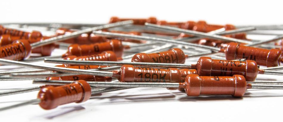
The components used in THT are generally larger than those used in Surface Mount Technology (SMT). This is due to the need for the components to have leads that can be inserted into the holes. The components used in THT include resistors, capacitors, and inductors, as well as integrated circuits (ICs).
The process of THT provides a strong mechanical bond between the component and the PCB. This is particularly beneficial in applications where the product may be subjected to physical stress, such as in military or aerospace applications. However, the robustness of THT comes at the cost of board space, as the components used are larger and the holes drilled into the PCB take up additional space.
Despite these limitations, THT remains a viable option for certain applications. It is particularly useful in prototyping stages where manual adjustments may be required, or in applications where the high mechanical strength provided by the through-hole assembly is necessary.[1]
Advantages of Through Hole Technology
Through Hole Technology, despite being one of the oldest methods of PCB assembly, still holds a significant place in the industry. Here is why:
Strong Mechanical Connections: One of the primary advantages of THT is the strong mechanical bond it forms between the components and the PCB. This is due to the components' leads being inserted into the drilled holes and then soldered, creating a robust connection. This makes THT suitable for applications where the PCB is subjected to physical stress or harsh environments, such as in aerospace, military, or automotive applications.
Ease of Prototyping and Manual Adjustments: The larger size of the components and their leads makes them easier to handle and manipulate, which can be beneficial during the prototyping stage or for small-scale production. This is particularly useful when frequent modifications are required, as components can be easily added, removed, or replaced.
High-frequency Applications: THT also offers better performance in high-frequency applications. This is because the leads in THT components can act as a short antenna, which can help in reducing the effects of radio frequency interference (RFI). This makes THT a preferred choice for high-frequency or radio frequency (RF) applications.
Better Heat Tolerance: THT components are generally more tolerant to heat compared to Surface Mount Technology (SMT) components. This is due to their larger size and the fact that they are not directly attached to the PCB surface. This makes THT a better choice for applications where the PCB is exposed to high temperatures, such as in power electronics or industrial machinery.
Easier Testing and Inspection: THT allows for easier inspection and testing of the assembled PCB. The visible connections make it easier to identify and rectify any hand-soldering defects or component misplacements. This can lead to improved product quality and high reliability, which is crucial in industries where failure is not an option.
Disadvantages of Through Hole Technology
Despite its advantages, Through Hole Technology also has its share of drawbacks. Some of these are:
Larger Components(which limit board space utilization): The need for drilled holes for each component lead consumes a considerable amount of PCB space. This not only limits the number of components that can be placed on the board but also restricts the routing of signal traces, which can impact the overall performance of the circuit. The larger size of THT components also contributes to this inefficiency. As electronic devices continue to shrink in size, the demand for smaller components and more compact PCBs is increasing. In this regard, THT often falls short compared to newer technologies like Surface Mount assembly, which allows for the placement of smaller components on both sides of the PCB.
More Labor-intensive and Slower Assembly Process: Another disadvantage of THT is the increased complexity and time consumption of the assembly process. The need to drill holes, insert leads, and solder them makes the THT process more labor-intensive and slower than SMT. This can lead to higher production costs, especially for high-volume manufacturing.
Longer Leads and Paths: THT also falls short regarding high-speed or high-frequency applications. The longer leads and paths can lead to increased inductance and capacitance, which can cause signal distortion at high frequencies. This makes THT less suitable for applications such as high-speed computing or telecommunications, where signal integrity is crucial.
Environmental Impact: The drilling process generates a significant amount of waste material, and the use of lead-based solder poses environmental and health risks. While lead-free solder options are available, they often come with their own set of challenges, such as higher melting points and potential reliability issues.
Understanding Surface Mount Technology
Surface Mount Technology (SMT) is a modern method used in the assembly of printed circuit boards. It has gained popularity over the past few decades due to its efficiency and the miniaturization it allows.
The Concept of Surface Mount Technology
Surface Mount Technology involves mounting electronic components directly onto the surface of a printed circuit board. Unlike Through-hole mounting technology, there is no need to drill holes into the PCB. Instead, surface mount components are soldered onto pads on the surface of the board. These surface mount components, known as Surface Mount Devices (SMDs), come in a variety of shapes and sizes, but they are generally much smaller than their through-hole counterparts.
The SMT process begins with the application of solder paste to the PCB. This is typically done using a stencil to ensure the paste is applied only to the designated pads. The components are then placed onto the paste-covered pads. This can be done manually for low-volume production or prototyping, but it is typically done using automated machines for high-volume production. Once all components are in place, the board is passed through a reflow oven, where the solder paste melts and forms a mechanical and electrical connection between the components and the board.
SMT has allowed for significant advancements in PCB design and complexity. It enables the placement of more components on both sides of the board, leading to higher circuit densities. It also allows for the use of smaller components, contributing to the ongoing trend of miniaturization in electronics. However, like any technology, SMT has its advantages and disadvantages, which we will explore in the following sections.[2]
Further reading: SMT Manufacturing: Everything You Need to Know
Advantages of Surface Mount Technology
Surface Mount assembly offers several advantages that have contributed to its widespread adoption in the electronics industry. Here are some:
Board Space Utilization: The absence of drilled holes and the smaller size of Surface Mount Devices (SMDs) allow for a higher component density on the PCB. This enables the design of more complex and compact circuits, which is particularly beneficial in today's era of miniaturized electronic devices.
Potential for automation: The placement of SMDs onto the solder paste-covered pads can be fully automated with pick-and-place machines, making the assembly process faster and more efficient. This is particularly beneficial for high-volume production, where speed and consistency are crucial. Automated assembly also reduces the risk of human error, leading to higher product quality and higher-reliability.
Superior Performance in High-frequency Applications: The shorter leads and paths in SMT components result in lower inductance and capacitance, reducing signal distortion at high frequencies. This makes SMT a preferred choice for applications such as high-speed computing or telecommunications, where signal integrity is crucial.
Environmentally Friendliness: The absence of drilled holes reduces waste material, and the smaller size of SMDs means less material is used in their manufacture. Additionally, the reflow soldering process used in SMT is more energy-efficient compared to the wave soldering process used in THT.
Placement of Components on Both Sides of the PCB: This doubles the available real estate for component placement, further contributing to the potential for miniaturization and complexity in PCB design. This is not typically possible with THT, as the leads of the components need to be soldered on the opposite side of the board.
Further reading: Demystifying Soldering Techniques: A Comparison of Wave Soldering and Reflow Soldering
Disadvantages of Surface Mount Technology
Despite its numerous advantages, Surface Mount Technology is not without its drawbacks. Some of them are:
Fragility of the Surface Mount Devices (SMDs): Due to their small size and the fact that they are soldered directly onto the surface of the PCB, SMDs are more susceptible to physical damage. This can be a concern in applications where the PCB is subjected to physical stress or harsh environments components
Difficulty in Manual Soldering and Rework: The small size of the SMDs and their close proximity on the PCB can make manual soldering challenging, increasing the risk of solder bridges or damage to nearby components. Similarly, rework (the process of correcting defects or making modifications after the initial assembly) can be more difficult and time-consuming with SMT compared to Through Hole Technology.
Higher Initial Setup Cost: The need for stencils for solder paste application and the use of automated placement machines can result in significant upfront costs. While these costs can be offset by the increased efficiency and speed of the SMT assembly process, they can be a barrier for small-scale production or prototyping.
Less Heat-tolerance: This is due to their smaller size and the fact that they are directly attached to the PCB surface. This can limit the use of SMT in applications where the PCB is exposed to high temperatures, such as in power electronics or industrial machinery.
Inspection and Testing Challenge: The small size of the SMD components and the fact that they are soldered directly onto the PCB surface can make it difficult to visually inspect the solder joints or probe the components for testing. This can require more sophisticated and costly inspection and testing equipment, adding to the overall cost of the SMT assembly process.
Through Hole vs Surface Mount: A Comparative Analysis
Through-hole technology and Surface Mount Technology represent two different approaches to PCB assembly, each with its strengths and weaknesses. A comparative analysis of these two technologies can provide valuable insights into their suitability for different applications.
Process Comparison
The through-hole assembly process involves drilling holes into the PCB, inserting the leads of the components into these holes, and then soldering the leads on the opposite side of the board. This process creates a strong mechanical bond between the components and the PCB, making THT suitable for applications where the PCB is subjected to physical stress. However, the need for drilled holes and the larger size of the components limit the board real estate utilization and increase the complexity and time consumption of the assembly process.
The assembly process for Surface Mount Technology involves applying solder paste to the PCB, placing the components onto the paste-covered pads, and then passing the board through a reflow oven to melt the solder paste and form the connections. This process allows for a higher component density and the placement of components on both sides of the board, contributing to the miniaturization and complexity of the circuits. However, the small size of the components and their direct attachment to the PCB surface can make them more susceptible to physical damage and less tolerant to heat.
In terms of automation, SMT has a clear advantage. The placement of components can be fully automated, making the assembly process faster and more efficient. This is particularly beneficial for high-volume production. In contrast, the THT process is more labor-intensive and slower, leading to higher production costs.
When it comes to performance in high-frequency applications, SMT is the preferred choice. The shorter leads and paths in SMT components result in lower inductance and capacitance, reducing signal distortion at high frequencies. In contrast, the longer leads and paths in THT can cause signal distortion at high frequencies.
From an environmental perspective, SMT is more favorable. The absence of drilled holes reduces waste material, and the reflow soldering process is more energy-efficient compared to the wave soldering process used in THT. However, the inspection and testing of SMT-assembled PCBs can be more challenging and require more sophisticated equipment, adding to the overall cost of the assembly process.
Component Durability
When it comes to component durability, Through-hole mounting generally has the upper hand. The mechanical bond created by inserting the leads of the components into the drilled holes and soldering them on the opposite side of the board provides a high level of durability. This makes THT components more resistant to physical stress, such as vibrations or impacts, making THT a suitable choice for applications where the PCB is subjected to harsh conditions or rough handling.
In contrast, Surface Mount Devices, due to their small size and the fact that they are soldered directly onto the surface of the PCB, are generally more fragile. They are more susceptible to damage from physical stress, which can be a concern in certain applications. However, it's worth noting that advancements in SMT component design and materials are continually improving their durability.
Another aspect to consider is thermal stress. THT components are generally more heat-tolerant compared to SMT components. This is due to their larger size and the fact that they are not directly attached to the PCB surface. This makes THT a better choice for applications where the PCB is exposed to high temperatures, such as power electronics or industrial machinery.
On the other hand, SMT components, due to their smaller size and direct attachment to the PCB surface, are generally less heat-tolerant. This can limit their use in high-temperature applications. However, like with physical durability, ongoing advancements in component design and materials are helping to improve the heat tolerance of SMT components.
Cost Implications
The cost implications of through-hole Technology and Surface Mount Technology can vary significantly depending on the specific circumstances.
In terms of initial setup costs, Surface Mount Technology generally requires a higher investment. This is due to the need for stencils for solder paste application and the use of automated placement machines. These upfront costs can be significant, particularly for small-scale production or prototyping. However, these costs can be offset by the increased efficiency and speed of the SMT assembly process in high-volume production scenarios.
On the other hand, the setup costs for through-hole Technology are generally lower. The equipment required for drilling holes and soldering components is less expensive than the equipment required for SMT. However, the assembly process for THT is more labor-intensive and slower, which can lead to higher production costs, particularly for high-volume production.
When it comes to component costs, SMT components are generally less expensive than their THT counterparts. This is due to their smaller size, which means less material is used in their manufacture. However, the smaller size of SMT components can also make them more difficult to handle and more susceptible to damage during assembly, which can lead to higher costs due to component wastage.
In terms of operational costs, SMT can offer significant savings due to its potential for automation. Automated assembly reduces labor costs and increases production speed, leading to lower per-unit costs. In contrast, the more labor-intensive THT process can result in higher operational costs.
Finally, the cost of inspection and testing can be higher for SMT. The small size of the SMD components and the fact that they are soldered directly onto the PCB surface can make it difficult to visually inspect the solder joints or probe the components for testing. This can require more sophisticated and costly inspection and testing equipment, adding to the overall cost of the SMT assembly process. In contrast, the inspection and testing of THT-assembled PCBs is generally simpler and less costly.[3]
Further reading: SMT Assembly vs. Through-Hole: What to Know
Choosing Between Through Hole and Surface Mount Technology
When deciding between through-hole Technology and Surface Mount Technology for a specific application, several factors must be taken into consideration. These factors can help guide the decision-making process and ensure the most suitable assembly method is chosen.
Factors to Consider
Component Size and Density: The size of the components and the desired component density on the PCB play a significant role in the choice between THT and SMT. If miniaturization and high component density are priorities, SMT is the more suitable option. However, if larger components or a more robust mechanical connection are required, THT may be the better choice.
Production Volume: The production volume can also influence the choice between THT and SMT. For high-volume production, the automation capabilities of SMT can lead to lower per-unit costs and faster production times. In contrast, for low-volume production or prototyping, the lower setup costs and ease of manual adjustments associated with THT may be more advantageous.
Application Requirements: The specific requirements of the intended application should also be considered. For example, if the PCB is exposed to high temperatures or physical stress, the durability of THT components may be more suitable. On the other hand, if high-frequency performance or miniaturization is a priority, SMT may be the better option.
Cost Implications: The overall cost implications of each assembly method should be taken into account. This includes not only the initial setup costs but also the ongoing operational costs, component costs, and inspection and testing costs. Balancing these factors can help determine the most cost-effective choice for a given project.
Environmental Impact: Lastly, the environmental impact of each assembly method should be considered. SMT is generally more environmentally friendly due to the absence of drilled holes, reduced material usage, and more energy-efficient soldering processes. However, the inspection and testing of SMT-assembled PCBs can be more challenging and require more sophisticated equipment, which may offset some of the environmental benefits.[4]
Application-Specific Considerations
The specific application of the PCB can greatly influence the choice between through-hole Technology and Surface Mount Technology.
In the power electronics industry, for instance, where components often need to handle high currents and voltages, the robust mechanical connections and heat tolerance of THT components can be particularly advantageous. This is because the larger size of THT components allows for greater heat dissipation, and the strong mechanical bond between the components and the PCB can withstand the physical stress caused by high currents.
In contrast, in applications such as mobile devices, laptops, or other compact electronics, the miniaturization and high component density offered by SMT are crucial. The small size of SMT components allows for more components to be placed on the PCB, enabling the creation of complex circuits within a limited real estate. Furthermore, the ability to place components on both sides of the PCB can further contribute to the compactness of the device.
In high-frequency applications, such as radio frequency (RF) communication systems or high-speed digital circuits, SMT is often the preferred choice. The shorter leads and paths in SMT components result in lower inductance and capacitance, reducing signal distortion at high frequencies.
For applications that require robustness and durability, such as industrial machinery or automotive electronics, THT may be the better choice. The strong mechanical bond between the components and the PCB in THT can withstand the vibrations and physical stress that these applications often entail.
In the end, the choice between THT and SMT will depend on a careful consideration of the specific requirements of the application, balancing factors such as component size and density, production volume, performance requirements, cost implications, and environmental impact.
Conclusion
Through-hole Technology and Surface Mount Technology each have their unique advantages and disadvantages. The choice between the two is not a matter of one being universally better than the other but rather depends on the specific requirements of the application.
THT offers robust mechanical connections and better heat tolerance, making it suitable for applications that require durability or are exposed to high temperatures. However, its assembly process is more labor-intensive and slower, and its larger components limit the board real estate utilization.
SMT, on the other hand, allows for miniaturization and high component density, making it ideal for compact electronics. Its assembly process can be fully automated, leading to increased efficiency and speed. However, its components are generally more fragile and less heat-tolerant.
The cost implications of each technology can also vary significantly, with SMT generally requiring a higher initial investment but potentially offering lower per-unit costs in high-volume production.
Frequently Asked Questions
What is the main difference between through-hole technology and Surface Mount Technology?
The main difference lies in how the components are attached to the PCB. In THT, components are inserted into drilled holes and soldered on the opposite side of the board. In SMT, components are soldered directly onto the surface of the PCB.
Which technology is more cost-effective?
The cost-effectiveness of each technology can depend on several factors, including the production volume, component costs, and operational costs. While SMT generally requires a higher initial investment, it can offer lower per-unit costs in high-volume production due to its potential for automation.
Which technology is more durable?
THT components are generally more durable due to the strong mechanical bond created by inserting the leads into the drilled holes and soldering them on the opposite side of the board. However, advancements in SMT component design and materials are continually improving their durability.
Which technology is better for high-frequency applications?
SMT is often the preferred choice for high-frequency applications. The shorter leads and paths in SMT components result in lower inductance and capacitance, reducing signal distortion at high frequencies.
Reference
Sinovoltaics, 2019. Through Hole Technology. Available at: https://sinovoltaics.com/learning-center/inverters/through-hole-technology/ (Accessed: December 3, 2023).
Abiola Ayodele(Wevolver), 2022. SMT Manufacturing: Everything You Need to Know. Available at: https://www.wevolver.com/article/smt-manufacturing-everything-you-need-to-know (Accessed: December 3, 2023).
Creative HiTech, 2020. Through-Hole Vs Surface Mount: What is The Difference? Available at: https://www.creativehitech.com/blog/throughhole-vs-surface-mount-what-is-the-difference-/ (Accessed: December 4, 2023).
Candor Circuit Boards, 2022. Surface Mount vs Through Hole. Available at: https://www.candorind.com/blog/surface-mount-vs-through-hole/ (Accessed: December 4, 2023).
in this article
1. Introduction to PCB Assembly Techniques2. Understanding Through Hole Technology3. Understanding Surface Mount Technology4. Through Hole vs Surface Mount: A Comparative Analysis5. Choosing Between Through Hole and Surface Mount Technology6. Conclusion7. Frequently Asked Questions8. Reference