Robot Joints: An In-Depth Guide to Anatomy, Physics and Challenges in Design
Robotic joints, which are sometimes known as axes, are the moveable parts of a robot that cause relative motion between adjacent links. These links refer to the rigid components that connect the joints to ensure their proper and straightforward operation.

Last updated on 06 Nov, 2023. 16 minutes read
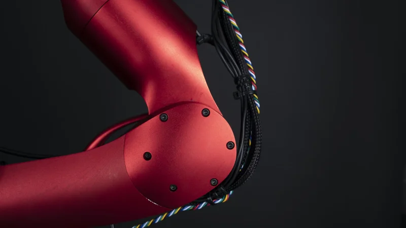
Robotic Arm
Introduction
Robotic joints are fundamental components in the field of robotics, playing a crucial role in the movement and functionality of robotic systems. They are the points of articulation that allow robots to move in specific ways, mimicking the movements of human joints like the elbow or knee. The importance of robotic joints extends beyond mere movement; they are integral to the robot's ability to interact with its environment in a precise and controlled manner.
Robotic joints are engineered to meet distinct requirements, and a design suitable for one application may not be transferable to another due to the diverse range of functionalities and operational demands within the field of robotics. They are designed and implemented based on the specific requirements of the robot and its intended function. For instance, a robotic arm used in a manufacturing assembly line may require different types of joints compared to a robot designed for complex surgical procedures.
In this article, we explore the anatomy, types, and physics of robotic joints, delving into their control systems and discussing the challenges encountered in their design and operation. Through a comprehensive analysis, we aim to provide a detailed understanding of how these fundamental components are engineered and controlled.
Further reading: What is Robotics? A Comprehensive Guide to its Engineering Principles and Applications
The Anatomy of a Robotic Joint
The anatomy of a robotic joint is orchestrated with a blend of mechanical and electrical components, each with a defined role, contributing to the joint's overall functionality and operation. These components, precisely engineered, work in unison to enable a robot to interact with its environment in a controlled and precise manner. Here’s a breakdown of these components:
Mechanical Components
The mechanical components of a robotic joint are the physical parts that facilitate movement. These include gears, linkages, and bearings, among others.
Gears: Fundamental to the functioning of a robotic joint, gears are toothed wheels engineered to mesh together, facilitating the transmission of torque and initiation of rotational motion. The intricacies in the arrangement and the genre of gears employed are pivotal as they markedly influence the joint's attributes of speed, torque, and precision. For instance, spur gears are a common choice owing to their simplistic design and adeptness in high power transmission efficiency. Conversely, in scenarios demanding a smoother and quieter operation, helical gears are favored notwithstanding their more sophisticated design and manufacturing requisites.
Linkages: In contrast, linkages are rigid entities interconnected by joints, orchestrating a system that bestows controlled motion. Within a robotic joint, linkages are the conduits for motion transfer from one segment of the robot to another. The architectural design of these linkages, inclusive of their length and configuration, bears a significant impact on the robot's ambit of motion and the intricacy of its movements.
Bearings: Bearings emerge as another indispensable mechanical component in a robotic joint, tasked with minimizing friction among moving parts and rendering support for rotational or linear movements. The breed of bearing selected is contingent on the specific operational demands of the robotic joint. For instance, ball bearings are a popular choice due to their proficiency in low friction and high rotational speed capabilities, whereas roller bearings are the go-to for applications necessitating higher load capacities.
Each of these mechanical components plays a vital role in the operation of a robotic joint. Their design and implementation can greatly influence the performance and capabilities of the robot.
Further reading: Robotic actuators: The muscle power of Industry 4.0
Electrical Components
The electrical components of a robotic joint are the elements that provide control and feedback. These primarily include motors and sensors.
Motors: Motors serve as the driving force behind the operation of a robotic joint, efficiently converting electrical energy into mechanical energy which is manifested as either rotational or linear motion within the joint. The specific type of motor utilized is contingent upon the particular requirements of the application. For example, DC motors are frequently selected due to their simplicity and ease of control. However, in scenarios demanding high precision and control, the preference often tilts towards Servo Motors or Stepper Motors. Servo motors are particularly notable for their ability to provide precise control over speed, position, and acceleration, making them an ideal choice for intricate applications such as maneuvering robotic arms or legs.
Sensors: On the other flank, sensors are pivotal in furnishing the robotic joint with the capability to interact intelligently with its environment by providing invaluable feedback to the control system. They are employed to measure critical parameters such as position, speed, and force which are essential for enhancing the control and functionality of the robotic joint. For instance, Rotary Encoders are utilized to determine the joint's position and speed by detecting the rotation of a disk affixed to the motor shaft. Similarly, Force Sensors, which include strain gauges or load cells, are used to measure the force exerted by or on the joint, supplying crucial feedback for tasks necessitating precision in object manipulation or balance control.
Further reading: Types of Sensors in Robotics
The integration of these electrical components into a robotic joint forms a closed-loop control system. This allows the robot to perform precise and controlled movements, adapt to changes in its environment, and perform complex tasks autonomously. The design and implementation of these electrical components are, therefore, crucial to the functionality and performance of a robotic joint.
Types of Robotic Joints
The design and functionality of robotic joints are pivotal in dictating the motion capabilities of robotic systems. These joints mimic human joint actions to some extent, allowing robots to perform a variety of tasks. Here’s an outline of the different types of robotic joints, primarily categorized based on their movement characteristics:
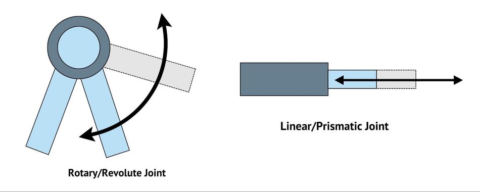
Rotary/Revolute Joints
Revolute joints, also known as rotary joints, are one of the most common types of robotic joints. They allow rotation around a single axis, similar to the way a door hinge operates. This type of joint is often used in robotic arms and legs, where it enables movements such as bending and straightening.
The design of a revolute joint typically involves a motor, which provides the rotational force, and a series of gears, which transmit this force to the joint. The motor's speed and direction of rotation determine the joint's movement. For instance, a DC motor rotating at a speed of 1000 revolutions per minute (RPM) might be used to achieve a specific joint speed, while changing the motor's direction of rotation would allow the joint to move in the opposite direction.
Revolute joints offer several advantages in robotics. They are relatively simple to design and control, making them a cost-effective choice for many applications. Furthermore, their single-axis rotation allows for precise control of the joint's position and speed, which is crucial in tasks such as object manipulation or path following.
However, revolute joints also have limitations. Their single-axis rotation restricts the range of motion compared to other joint types, such as spherical or universal joints. Additionally, the mechanical stress on the joint's components can be high, especially in applications involving heavy loads or high speeds. Therefore, careful design and material selection are essential to ensure the joint's durability and performance.
Linear/Prismatic Joints
Prismatic joints, also known as linear joints, are another type of robotic joint that allows movement along a straight line. Unlike revolute joints, which provide rotation around an axis, prismatic joints enable linear motion, similar to the way a drawer slides in and out of a cabinet. This type of joint is commonly used in robotic systems that require precise linear positioning, such as pick-and-place machines or 3D printers.
The design of a prismatic joint typically involves a linear actuator, which generates the linear force, and a set of guide rails or tracks, which constrain the motion to a straight line. The linear actuator can be an electric motor coupled with a lead screw or ball screw, a pneumatic or hydraulic cylinder, or even a piezoelectric actuator for applications requiring extremely precise positioning. The choice of actuator depends on factors such as the required speed, force, and precision of the joint.
Prismatic joints offer several advantages in robotics. Their linear motion allows for precise positioning along a straight path, which is essential in tasks such as assembly or material handling. Additionally, prismatic joints can provide high force capabilities, especially when using hydraulic or pneumatic actuators, making them suitable for applications involving heavy loads.
However, prismatic joints also have some limitations. Their linear motion restricts the range of motion compared to other joint types, such as revolute or spherical joints. Furthermore, the mechanical components of a prismatic joint, such as the guide rails and actuator, can be susceptible to wear and tear, especially in applications involving high speeds or heavy loads. As with revolute joints, careful design and material selection are crucial to ensure the joint's durability and performance.
Other commonly used types of robotic joints include:
Spherical Joints: Spherical joints provide a broader spectrum of movement by allowing rotational motion around two perpendicular axes. This kind of joint is instrumental in robotic systems that demand a high degree of flexibility, like in some advanced humanoid robots. The dual-axis rotation feature of spherical joints significantly enhances the range of motion, enabling more complex and natural movements, which is particularly beneficial in robots designed to interact with dynamic environments.
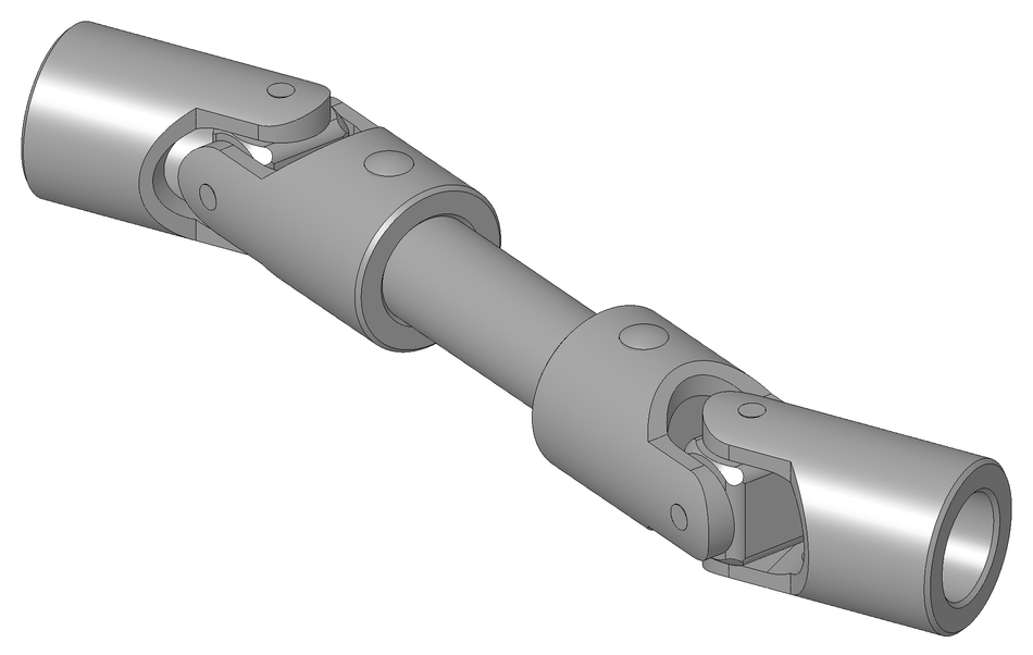
- Universal Joints: Universal joints are known for their capability to allow rotation in two different planes, thus offering more flexibility compared to revolute joints. They find their use predominantly in scenarios like drive shafts where two non-aligned axes need to be connected. The design of universal joints is slightly more complex, but their ability to connect misaligned axes makes them indispensable in certain robotic and mechanical applications.
Cylindrical Joints: Cylindrical joints are unique as they amalgamate linear and rotational movements, hence providing a broader spectrum of motion within a cylindrical coordinate system. This kind of joint is beneficial in scenarios where both types of movements are needed simultaneously. The design of cylindrical joints is inherently more complex, but their ability to provide a mix of linear and rotational movement makes them a valuable addition to certain robotic systems.
Planar Joints: Planar joints are specialized to allow movement within a plane, providing two translational degrees of freedom and one rotational degree of freedom. They are often incorporated in applications like painting or welding robots where planar motion is essential. The design of planar joints is tailored to ensure smooth movement within a plane, thus enabling robots to perform tasks with a high degree of accuracy and efficiency.
Further reading: 7 Types of Industrial Robots: Advantages, Disadvantages, Applications, and More
The Physics of Robotic Joints
Understanding the physics principles that govern the operation of robotic joints is essential for designing and controlling these components effectively. These principles can be broadly categorized into kinematics and dynamics, which together form the foundation of robotic joint operation.
Kinematics of Robotic Joints
Kinematics is the study of motion without considering the forces that cause it. In the context of robotic joints, kinematics focuses on the relationship between the joint's position, velocity, and acceleration. One key concept in kinematics is the degree of freedom (DOF), which refers to the number of independent parameters that define the motion of a system.
For robotic joints, the DOF is determined by the type of joint and its configuration. For example, a revolute joint has one DOF, as it allows rotation around a single axis. A prismatic joint also has one DOF, as it permits linear motion along a straight line. More complex joints, such as spherical or universal joints, can have multiple DOFs, allowing for a greater range of motion.
Understanding the kinematics of robotic joints is crucial for designing and controlling these components. For instance, the kinematic equations can be used to calculate the joint's position, velocity, and acceleration based on the input from the motor or actuator. This information can then be used to develop control algorithms that ensure the joint moves accurately and smoothly, following a desired trajectory or path.
In addition, kinematic analysis can help identify the workspace of a robotic system, which is the set of all possible positions the robot can reach. This information is valuable for determining the robot's capabilities and limitations, as well as for optimizing its design and configuration for specific tasks or applications.
Dynamics of Robotic Joints
While kinematics deals with the motion of robotic joints without considering the forces that cause it, dynamics takes into account these forces and the resulting torques. Dynamics is crucial for understanding how a robotic joint will respond to certain inputs and how it will interact with its environment.
The dynamics of a robotic joint are governed by Newton's second law of motion, which states that the force applied to an object is equal to its mass times its acceleration. In the context of robotic joints, this force is often the torque applied by the motor or actuator, while the mass is the inertia of the joint and the connected components, and the acceleration is the angular or linear acceleration of the joint.
One key concept in dynamics is the dynamic model of the joint, which is a mathematical representation of the joint's motion considering the applied forces or torques. This model typically includes terms related to the joint's inertia, damping (resistance to motion), and stiffness (resistance to deformation), as well as any external forces or torques acting on the joint.
Developing an accurate dynamic model is essential for controlling a robotic joint effectively. For instance, the model can be used to predict the joint's response to a given motor input, allowing the control system to adjust the input as needed to achieve a desired motion. Furthermore, the dynamic model can help identify potential issues or limitations, such as excessive vibrations or instability, and guide the design and tuning of the joint to mitigate these issues.
However, developing a dynamic model can be challenging due to the complexity of the joint's motion and the various factors that can influence it, such as friction, backlash (looseness), or non-linearities in the motor's response. Therefore, advanced techniques, such as system identification or machine learning, are often used to derive or refine the model based on experimental data.
In addition to the dynamic model, other concepts in dynamics, such as energy conservation or momentum conservation, can also be useful for understanding and controlling robotic joints. For example, these principles can be used to analyze the joint's behavior during collisions or other interactions with the environment, or to develop control strategies that minimize the joint's energy consumption.
Control Systems for Robotic Joints
Control systems play a vital role in the operation of robotic joints, ensuring that the joint moves accurately and smoothly according to the desired trajectory or path. There are two main types of control systems used in robotics: open-loop and closed-loop control systems.
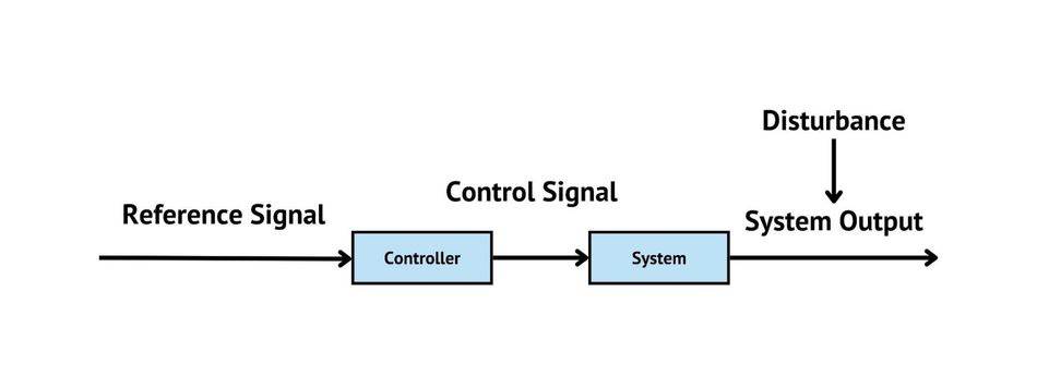
Open-Loop Control Systems
Open-loop control systems are relatively simple and straightforward, as they do not rely on feedback from the joint to adjust the control input. Instead, the control input, such as the motor voltage or current, is determined solely based on the desired joint position, velocity, or acceleration.
In an open-loop control system, the control algorithm calculates the required motor input based on the desired motion and the joint's dynamic model. This input is then applied to the motor, and the joint moves accordingly. However, since there is no feedback from the joint, the control system cannot correct for any errors or disturbances that may occur during the motion, such as friction, backlash, or external forces.
Despite their simplicity, open-loop control systems can be effective for certain applications, particularly those with low precision requirements or minimal external disturbances. For example, open-loop control may be suitable for a robotic joint used in a pick-and-place machine, where the joint's motion is relatively simple and the environment is controlled.
However, open-loop control systems have several limitations. They are highly sensitive to errors in the joint's dynamic model, as any inaccuracies in the model can result in significant deviations from the desired motion. Furthermore, open-loop control systems cannot adapt to changes in the joint's properties or the environment, such as wear and tear, temperature variations, or external disturbances. As a result, closed-loop control systems are often preferred for applications requiring higher precision and adaptability.
Closed-Loop Control Systems
Closed-loop control systems, in contrast to open-loop systems, rely on feedback from the joint to adjust the control input continuously. This feedback allows the control system to correct for errors or disturbances that may occur during the motion, resulting in more accurate and stable joint operation.
In a closed-loop control system, sensors such as encoders or force sensors are used to measure the joint's position, velocity, or force. This information is then compared to the desired motion, and the control algorithm calculates the required motor input to minimize the error between the actual and desired motion. The motor input is then adjusted accordingly, and the joint moves towards the desired position or along the desired trajectory.

Closed-loop control systems offer several advantages over open-loop systems. They are less sensitive to errors in the joint's dynamic model, as the feedback allows the control system to correct for inaccuracies in the model or changes in the joint's properties. Furthermore, closed-loop control systems can adapt to external disturbances, such as friction, backlash, or external forces, ensuring that the joint maintains its desired motion even in the presence of these disturbances.
However, closed-loop control systems are more complex than open-loop systems, as they require additional components, such as sensors and feedback controllers. This complexity can increase the cost and development time of the robotic joint. Additionally, closed-loop control systems can be susceptible to issues such as sensor noise, latency, or instability, which can affect the joint's performance and require careful tuning of the control algorithm.
Despite these challenges, closed-loop control systems are often preferred for applications requiring high precision and adaptability, such as robotic arms used in manufacturing or surgery. By leveraging feedback from the joint, closed-loop control systems can ensure accurate and stable operation, even in the presence of errors, disturbances, or changing conditions.
Challenges in Designing Robotic Joints
Designing robotic joints involves overcoming several challenges to ensure optimal performance, durability, and adaptability. Some of the main challenges include:
Friction and Wear: Friction between moving parts in a robotic joint can lead to energy loss, reduced efficiency, and increased wear and tear. Selecting appropriate materials, lubrication, and bearing types can help mitigate these issues, but finding the right balance between performance, durability, and cost can be difficult.
Material Selection: The choice of materials for constructing robotic joints significantly affects their performance, durability, and the cost. Materials need to withstand the stresses and loads encountered during operations, and their selection is critical especially in applications where weight is a concern.
Backlash: Backlash, or looseness, in the mechanical components of a robotic joint can result in reduced precision and control. Minimizing backlash is essential for applications requiring high accuracy, such as robotic surgery or assembly. This can be achieved through careful design and manufacturing, as well as the use of specialized components, such as anti-backlash gears or preloaded bearings.
Non-linearities and Uncertainties: The dynamic behavior of a robotic joint can be influenced by various non-linearities and uncertainties, such as friction, motor response, or sensor noise. Developing accurate dynamic models and control algorithms that account for these factors can be challenging, often requiring advanced techniques, such as system identification or machine learning.
Thermal Effects: Temperature variations can affect the performance and durability of a robotic joint, causing changes in material properties, thermal expansion, or reduced efficiency of electrical components. Designing joints that can withstand temperature fluctuations and maintain consistent performance is crucial, especially for applications in harsh or variable environments.
Integration, Standardization and Compatibility: Robotic joints must be designed to integrate seamlessly with the rest of the robotic system, including the control hardware, software, and other mechanical components. Ensuring compatibility and interoperability between these elements can be challenging, particularly when dealing with complex systems or off-the-shelf components.
Maintenance Requirements: Robotic joints require maintenance to ensure smooth operation over time. Designing joints that are easy to maintain or self-maintaining (e.g., self-lubricating) can significantly reduce downtime and operational costs. Incorporating real-time monitoring and diagnostic capabilities can help in early detection of issues like wear, misalignment, or other potential failures, thus preventing costly downtime and repairs.
Cost Constraints: Designing highly functional and durable robotic joints can be expensive. Balancing cost while maintaining performance and reliability is a continual challenge. This also extends to the cost of maintenance and repairs over the robot's operational life.
Scalability: The design should be scalable to meet evolving needs or to adapt to new applications. Scalable designs can prolong the usefulness of the robot and allow for more straightforward upgrades or modifications.
Addressing these challenges requires a thorough understanding of the underlying physics, materials, and control principles, as well as a systematic approach to design, testing, and optimization. By overcoming these challenges, engineers can develop robotic joints that are efficient, precise, and adaptable, enabling robots to perform a wide range of tasks and applications.
Conclusion
Robotic joints, as the fundamental building blocks of robotic systems, play a crucial role in the functionality and performance of robots. The design, control, and operation of these joints are complex tasks that require a deep understanding of various disciplines, including mechanical engineering, electrical engineering, and computer science. Despite the challenges, advancements in technology continue to push the boundaries of what is possible, leading to more efficient, reliable, and versatile robotic systems.
Frequently Asked Questions
1. What are robotic joints? And what are their primary functions?
Robotic joints are crucial components that enable movement in robots by connecting various links or segments. They facilitate precise and controlled movements, allowing robots to interact with their environment and carry out tasks like picking, placing, welding, or even surgical operations. The functionality and design of robotic joints are inspired by human anatomy to create a range of motion that can mimic or even surpass human capabilities in certain aspects.
2. What are the main types of robotic joints?
The two main types of robotic joints are revolute and prismatic. Revolute joints rotate around a single axis, while prismatic joints move along a straight line.
3. How is the performance of robotic joints measured?
The performance of robotic joints is often measured by their precision, speed, and the load they can handle. Other factors include their range of motion, backlash, and the level of control that can be exerted over them. The reliability and maintenance requirements are also crucial for assessing their performance, especially in industrial settings.
4. What roles do control systems play in the operation of robotic joints?
Control systems are pivotal in the operation of robotic joints, as they govern the movement and coordination of these joints. They ensure that the joints move accurately to the desired positions, maintain the correct speed and torque, and adapt to any changes in the task or environment. Moreover, advanced control systems can provide real-time feedback, enabling adjustments and ensuring the robot performs tasks efficiently and safely.
5. What are some challenges in designing robotic joints?
Designing robotic joints involves many challenges, including ensuring the joint's strength and durability, optimizing its power consumption, and minimizing its size and weight. Additionally, the joint must be designed to accurately and reliably perform its intended movements.
References
[1] Siciliano B, Khatib O, editors. Springer handbook of robotics. 2nd ed. Springer International Publishing, 2016. Available from: https://link.springer.com/book/10.1007/978-3-540-30301-5
[2] Proceedings of the IEEE International Conference on Robotics and Automation (ICRA), IEEE Press, Available from: https://ieeexplore.ieee.org/xpl/conhome/1000639/all-proceedings
[3] Groover, Mikell P.. "automation". Encyclopedia Britannica, 4 Oct. 2023, https://www.britannica.com/technology/automation
[4] AZoRobotics. The Development of a Revolutionary Robotics Control System. Available from: https://www.azorobotics.com/Article.aspx?ArticleID=237