Linear Actuator Motor: Choosing the Right Motor Technology for Modern Linear Actuators
This article is a complete linear actuator motor selection guide, explaining how motor topology, drive selection, transmission design, force, speed, and duty cycle define electric linear actuator performance.

04 Jun, 2026. 18 minutes read
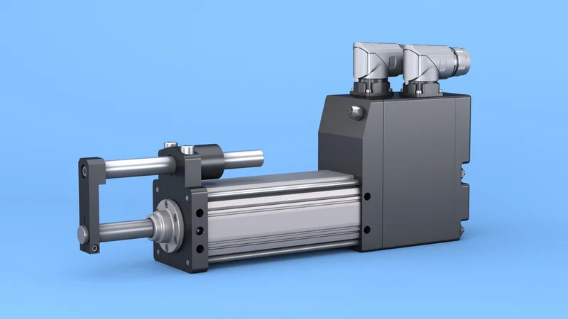
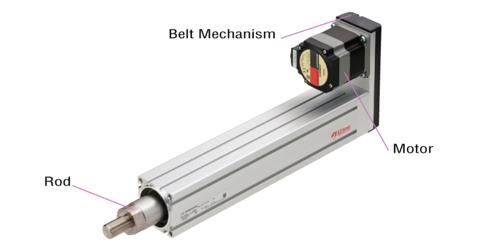
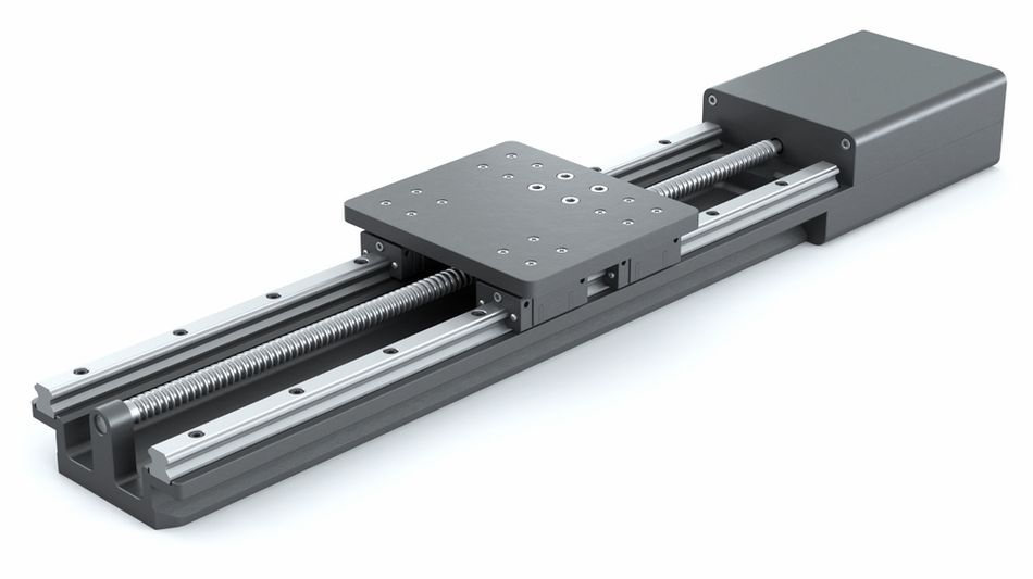
Exlar Linear Actuator
Key Takeaways
Motor Selection Impact: The motor inside a linear actuator can be a brushed DC, brushless DC (BLDC), stepper, servo, or direct-drive linear motor. LA36 brushed DC actuator delivers up to 6,800 N at 17 mm/s (no-load, 20% duty cycle), while the IMA integrated servo actuator reaches 35.8 kN at 1.33 m/s.
Force-Speed Calculations: The output force = motor torque × gear ratio × (2π / screw lead) × efficiency. Example: a 250 N horizontal load on a 10 mm lead ball screw with 85% efficiency requires ≈ 0.47 N·m of motor torque.
Transmission Mechanisms: Lead (Acme) screws are self-locking and rugged but only 30–60% efficient. Ball screws achieve 80–90% efficiency at speeds above 1 m/s. Roller screws handle thrusts above 30 kN. Belt drives suit high-speed light-load motion; direct-drive linear motors eliminate screw and gear losses entirely.
Duty Cycle and Reliability: Heavy-duty DC actuators like CAHB-22 have a 10–20% duty cycle at 42–55 mm/s. Servo-driven cylinders such as ESBF deliver 100% duty cycle, feed forces up to 17 kN, and ±0.01 mm repeatability.
Feedback and Loop Closure: Brushed DC uses limit switches; BLDC needs Hall sensors for commutation; stepper and servo actuators integrate absolute encoders or resolvers for closed-loop positioning; direct-drive linear motors rely on high-resolution linear encoders.
Ingress Protection Standards: IP65 resists dust and low-pressure water; IP66 withstands high-pressure spray; IP67 allows 1 m/30 min submersion; IP68 supports continuous immersion.
Introduction
The linear actuator motor is an electric machine within an electric linear actuator that generates rotary torque and converts it into straight-line motion via mechanisms such as screws or belts. Modern applications demand higher precision, efficiency, durability, and compact integration; selecting the right motor technology has become a key engineering decision. The linear actuator motor may use brushed DC, brushless DC, stepper, servo, or AC motor technology. Each offers different advantages in speed control, load capacity, positioning accuracy, maintenance, and cost.
Engineers must evaluate operating conditions, duty cycle, stroke length, feedback requirements, and environmental constraints before choosing the most suitable solution. The performance of a linear actuator motor directly affects system reliability, motion smoothness, energy consumption, and long-term service life. This article explores the main motor technologies used in linear actuators and explains how to choose the right linear actuator motor for modern motion-control applications.
What is a Linear Actuator Motor?
The linear actuator converts rotary motion into controlled linear motion or linear displacement using a mechanical transmission system. The linear actuator motor is a rotary electric motor that provides the input torque required to drive this motion. Separating the motor from the complete actuator system helps engineers evaluate performance, efficiency, force output, and control requirements more accurately.
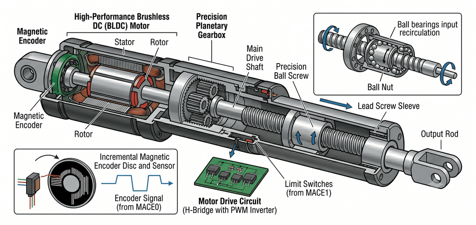
The electric actuator typically consists of:
Motor — Generates torque. Types include brushed DC, BLDC, stepper, servo (AC or DC), and direct-drive linear motors.
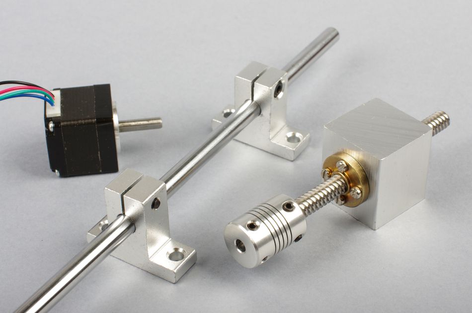
Transmission — Converts motor rotation into linear displacement. Common mechanisms include lead screws, ball screws, roller screws, belts, and rack-and-pinion. Each has its own mechanical advantage and efficiency.
Gearbox — Many actuators incorporate a gear reduction between motor and screw to increase output force at the cost of speed.
Bearings and Guides — Support axial and radial loads and maintain alignment.
Feedback Devices — Limit switches, Hall sensors, encoders, or resolvers provide position and speed information for control.
Housing, Seals and Connectors — Protect against environmental ingress and provide mounting.
Understanding the motor independently allows engineers to correctly size torque, speed, and power and to select the right transmission and feedback for the application.
Recommended Reading: What is an Actuator? Types, Principles, and Applications
Motor Topologies in Linear Actuators
This section compares the major motor types used in linear actuators, highlighting their characteristics, advantages, practical examples, and datasheet values.
Brushed DC Motors
Brushed DC motors remain popular in low-cost actuators because they are inexpensive, simple to drive, and deliver high starting torque. They commutate via mechanical brushes and a commutator, making them prone to brush wear and electrical noise. The typical efficiencies range from 75–80%. Duty cycles are limited because heat builds up at high currents.
Example — Linak LA36: This heavy-duty linear actuator uses a brushed DC motor with spur gearing and a ball screw. The 12 V datasheet lists 6,800 N thrust with a 12 mm screw lead and 1:46 gear ratio. Under these conditions, it achieves ≈ 17 mm/s no-load speed and draws ≈2.2 A at full load with a 20% duty cycle. [1] The stroke lengths range from 100 mm to 1,000 mm. This type of actuator is commonly used in agricultural machinery, off-road vehicles, industrial equipment, and solar trackers.
Example — SKF CAHB-22 E: Permanent-magnet DC motors output 55 mm/s at no load and 42 mm/s at rated load. Rated current is about 20 A for 12 V models and about 9 A for 24 V models. Duty cycle is typically 10% for 12 V versions and 20% for 24 V versions. With IP69K protection and stroke lengths from 50 mm to 700 mm, it demonstrates the typical trade-off in brushed DC actuators: strong environmental protection and useful thrust, but limited continuous-duty capability.
Example — Firgelli FA-RA-22: This compact brushed DC actuator uses a lead screw. It provides a dynamic force of about 22 lb, or 98 N, and a static load rating of 44 lb, or 195 N. No-load speed is approximately 9 in/s, or 229 mm/s, while full-load speed is about 4.5 in/s, or 114 mm/s. The current draw can reach up to 5 A, and the duty cycle is specified at 20%. [2] This example shows how lower-load DC actuators often prioritize speed and compact packaging over high force.
Brushed DC motors suit moderate forces (<10 kN), limited duty cycles, and cost-sensitive applications: adjustable furniture, hatches, agricultural equipment, solar trackers.
Brushless DC (BLDC) Motors
BLDC motors eliminate mechanical brushes via electronic commutation. They provide higher efficiency (75–90%), longer life, and lower electromagnetic noise than brushed DC motors. BLDC motors require Hall sensors or back-EMF detection for commutation and typically integrate an electronic driver.
Example — Ultra Motion A-Series Servo Cylinder: Integrates a BLDC motor with a ball screw and built-in controller. Peak force 530 lbf (2.36 kN), continuous force 270 lbf (1.20 kN), speed up to 14 in/s (356 mm/s), strokes up to 7.75 in (197 mm). Built-in absolute position sensor, CAN 2.0B / RS-485 communication, IP50–IP68 protection, −40 °C to 80 °C operating range.
Example — Maxon GP8S/GP16S Gearheads: These gearhead assemblies with ceramic screws can transmit up to 315 N of linear force. These compact motion systems are suitable for medical devices, laboratory automation, precision robotics, and small machine designs where high-quality motion, compact packaging, and long service life are important.
BLDC motors offer higher speed and continuous duty than brushed DC. These are suitable for high-precision automation, robotics, medical devices, and aerospace systems, especially when combined with ball or roller screws.
Stepper Motors
Stepper motors produce discrete stepwise motion and hold position without feedback. Once integrated with a lead screw or ball screw, the combination converts rotary motion into linear motion. Stepper actuators often include gear reductions to increase thrust and may incorporate closed-loop control to improve torque utilization.
Example — Oriental Motor EACM6E25AZMK: The Oriental Motor EACM6E25AZMK is a straight-type electric linear actuator using a closed-loop AZ series stepper motor. It uses a 6 mm lead and offers a 250 mm stroke. Maximum speed is 300 mm/s, thrust is approximately 400 N, and push force is approximately 500 N. Load capacity is about 60 kg horizontally and 30 kg vertically, with repeatability of ±0.02 mm.
Stepper-based actuators are common in low-to-medium-force applications: pick-and-place, laboratory automation, and small gantry stages where incremental positioning suffices. The closed-loop steppers (step-servo) overcome resonance and stall problems, delivering higher torque at high speeds.
AC/DC Servo Motors
Servo motors combine a high-performance electric motor (BLDC or AC synchronous) with feedback and a servo drive to provide precise torque and speed control. In linear actuators, servo motors enable high thrust, high speed, and continuous duty cycles. They operate with closed-loop current and position control, enabling accurate positioning and smooth motion.
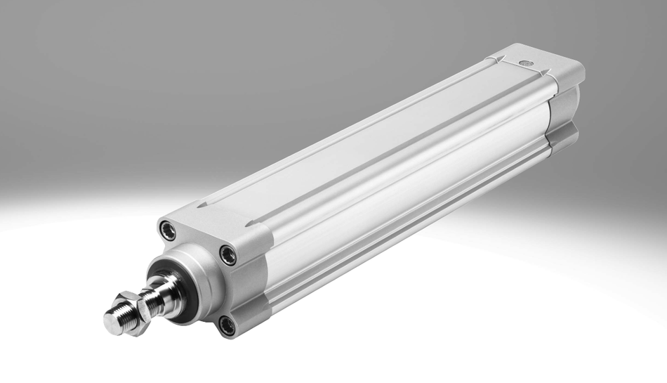
Example — Festo ESBF Electric Cylinder: This rod-style actuator is compatible with servo or stepper motors. It uses ball screw technology in most configurations, with lead screw options in smaller sizes. Feed forces range from about 1 kN to 17 kN, strokes extend up to 1.5 m, and maximum speeds range from approximately 1.1 m/s to 1.35 m/s. The actuator offers repeatability of ±0.01 mm and supports 100% duty cycle operation. It also includes options such as IP65 protection kits, guide units, and compatibility with food-safe lubricants.
Example — Parker ET Series: Uses servo motors and ball screws to provide high thrust and high speed in demanding industrial applications. Depending on the configuration, thrust can reach up to 5,300 lb (23.6 kN), while speeds can reach up to 60 in/s (1.524 m/s). High-thrust bearings support continuous operation, and the platform can be configured with microstepping or brushless servo motor options. [4]
Example — Tolomatic IMA Integrated Servo Actuators: Integrates a servo motor into a ball or roller-screw actuator, providing up to 35.8 kN thrust and 1.334 m/s speed. The stroke lengths can reach up to 457 mm (18 in.). Hygienic versions also offer IP69K protection.
Servo-driven actuators are the preferred choice when a machine requires high force, high speed, high precision, long duty cycle, and advanced motion control.
Linear Motors (Direct Drive)
The direct-drive linear motors create linear force without mechanical conversion by "unwrapping" a rotary motor. Ironless or iron-core primary coil glides over a magnet track. They provide high acceleration, zero backlash, and unlimited travel length. Because there is no screw or belt, linear motors achieve high speeds and exceptional positioning accuracy but require linear bearings to support the moving carriage.
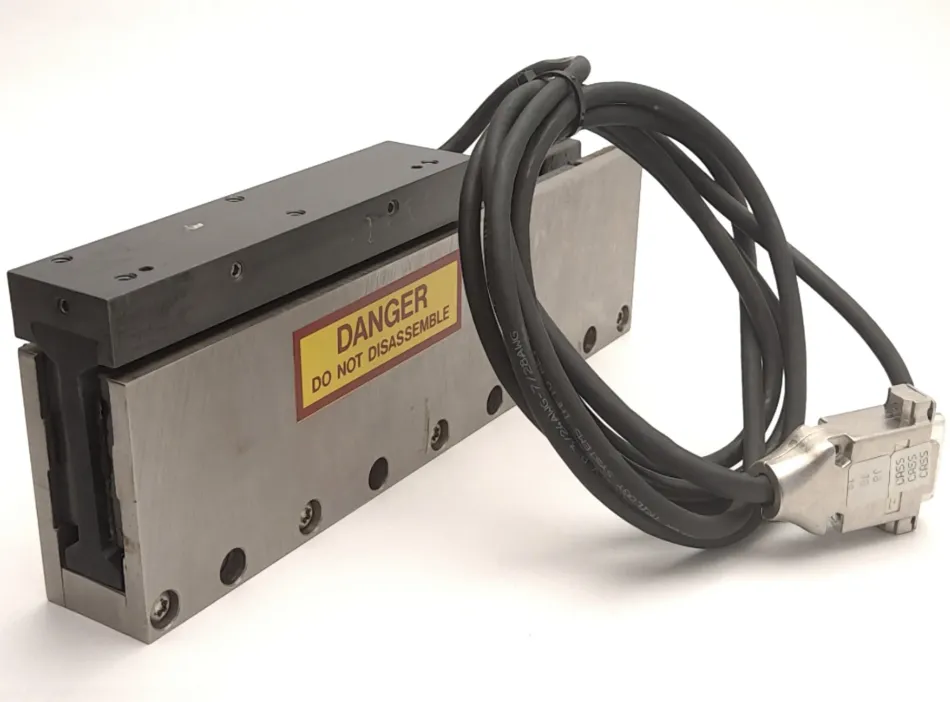
Example — Parker I-Force Ironless Linear Motors: Continuous force 12–1,614 N, peak force 42–7,261 N, unlimited track lengths, optional air or liquid cooling. They support unlimited track lengths and can include optional air or liquid cooling. The ironless construction eliminates cogging, allowing smooth motion and high acceleration.
These motors typically use external linear encoders for feedback and can achieve micron-level repeatability when integrated with precision bearings and advanced servo control. They are widely used in semiconductor manufacturing, laser machining, metrology, high-speed pick-and-place systems, and precision motion stages.
Linear motors are used in high-precision stages for semiconductor manufacturing, laser machining, pick-and-place, and metrology. They require sophisticated drives and careful thermal management but eliminate mechanical wear from screws and gears.
Recommended Reading: Actuator Motor: Differences Between Actuators and Motors, Selection, and Applications
How Motor Choice Drives Actuator Force, Speed, and Duty Cycle?
The output force and speed of the actuator are not inherent to the motor alone but result from a cascade of mechanical transformations:
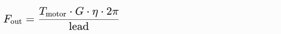
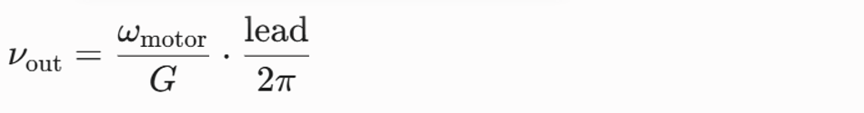
where:
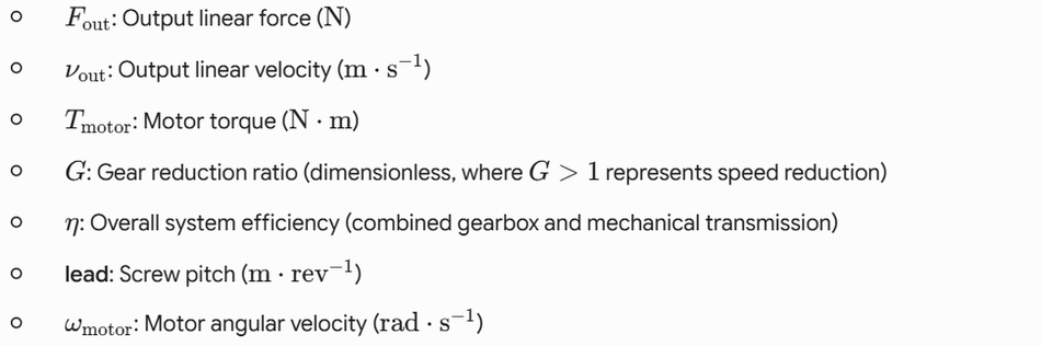
This model shows that increasing the gear ratio or decreasing the screw lead boosts force but lowers speed; the product of force and speed (mechanical power) remains constant minus losses. Efficiency depends on the transmission: ball screws: 80–90%, lead screws 30–60%, roller screws up to 90%, belt drives ≈90%. The gearboxes add further losses (1–3% per stage). [2]
Calculation Example
Move a 250 N horizontal load at 300 mm/s over a 500 mm stroke. Select a ball-screw actuator with 10 mm lead and 85% efficiency. The motor torque requirement is:
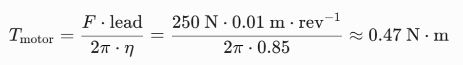
The standard NEMA 17 stepper motor, with a torque rating of around 0.5 N·m, can satisfy this requirement without gearing. To increase thrust margin or reduce current, a 2:1 gear reduction may be chosen, doubling output torque (≈0.94 N·m) and halving screw rotational speed. If the linear speed is 300 mm/s, the screw rotates at:
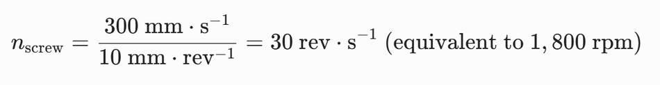
With a 2:1 reduction, the motor must rotate at twice this frequency:

Here, the duty cycle must be considered: stepper motors can operate continuously at rated current if properly cooled, but high speeds may cause resonance and require a closed-loop driver.
Duty Cycle and Motor Selection
The duty cycle, defined as the ratio of active run time to total cycle time, influences motor sizing.
Brushed DC actuators are specified with a 10–20% duty cycle because the brushes and windings cannot dissipate heat continuously. Conversely, industrial servo actuators achieve a 100% duty cycle, allowing continuous operation. Once a motor is selected, ensure that continuous torque or current is sufficient for the duty cycle. Oversizing the motor or choosing BLDC/servo technology increases duty cycle margin.
Transmission Pairing
The mechanical interface between the motor and the load significantly impacts performance. The motor type influences which screw or belt mechanism is optimal.
Lead (Acme) Screws
Lead screws feature trapezoidal threads and produce a large mechanical advantage. They are self-locking, eliminating back-driving without brakes. Frictional losses reduce efficiency to 30–60%; speeds are limited by nut wear and heat. Lead screws pair well with brushed DC motors in low-duty or static-holding applications such as adjustable furniture — the self-locking property maintains position when power is removed.
Ball Screws
Ball screws use recirculating ball bearings between screw and nut to reduce friction, achieving 80–90% efficiency. [3] They allow higher speeds and longer life. Ball screws are common with stepper, BLDC, and servo motors because their low friction reduces torque requirements and improves repeatability.
Roller Screws
Planetary roller screws replace balls with threaded rollers to handle very high thrust and life. They offer efficiencies similar to ball screws but support forces above 30 kN. Roller screws suit servo motors in heavy industrial machines, presses and injection moulding.
Belts and Rack-and-Pinion
Belt drives and rack-and-pinion mechanisms convert rotary motion through toothed belts or gears. They allow very long strokes and high speeds (often above 3 m/s) but trade off thrust capacity. Belts pair well with high-speed BLDC or AC servo motors for pick-and-place and gantry axes where loads are moderate (<1 kN). Belt-driven actuators often integrate planetary gearboxes to match motor speed.
Linear Motors
Direct-drive linear motors dispense with screw mechanisms entirely. They connect motors to the load via a carriage and magnet track, achieving zero backlash and unlimited stroke length. Because there is no mechanical reduction, linear motors need high-precision linear bearings and encoders. They pair with servo drives and are ideal for applications demanding micron-level accuracy and high acceleration, such as semiconductor handling and metrology.
Feedback and Control Architectures
Precise motion control in a linear actuator depends on the correct feedback architecture. Sensor selection is determined by motor type, positioning accuracy, duty cycle, safety requirements, and actuator controller complexity.
Below are the main feedback and control components used in modern linear actuator systems:
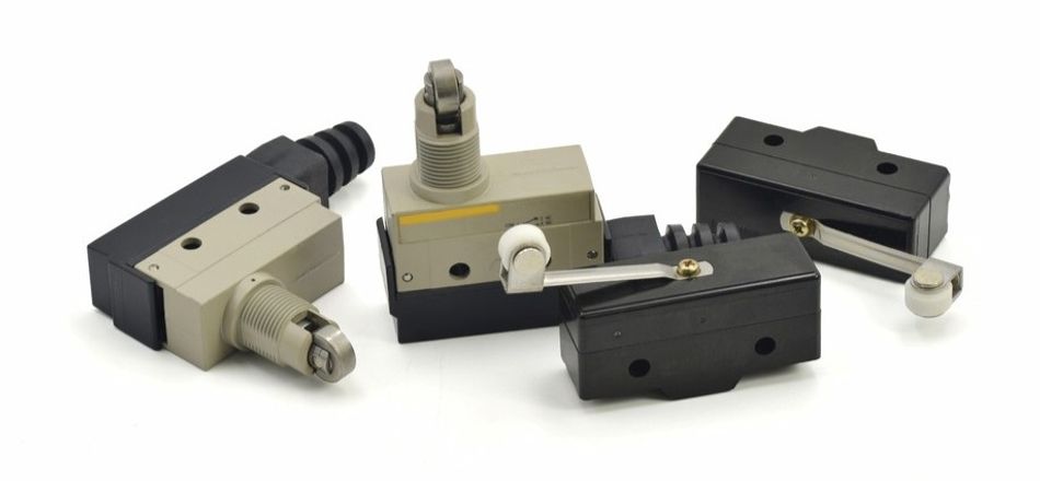
Limit Switches: Brushed DC actuators often rely on mechanical limit switches to stop motion at the end of travel. Simple end-stop detection, but no intermediate-position feedback.
Hall Sensors: BLDC motors use Hall-effect sensors for electronic commutation. In linear motors, Hall arrays can assist commutation, but high-resolution linear encoders handle positioning.
Encoders: Incremental or absolute rotary encoders mount on stepper and servo motors. Absolute encoders retain position after power loss. The Oriental Motor EAC series uses a battery-free absolute encoder integrated into the stepper for closed-loop control.
Resolvers: Some industrial servo motors employ resolvers (analog magnetic position sensors) for high reliability in harsh environments. Tolomatic offers resolver feedback options for its IMA actuators.
Linear Encoders: Direct-drive linear motors require linear encoders (optical or magnetic) with micron- or nanometre-level resolution to close the servo loop.
Integrated Electronics: Modern BLDC and servo actuators integrate drive electronics and controller into the actuator housing, simplifying wiring and enabling communication via CANopen, EtherCAT or RS-485. Integrated diagnostics monitor temperature, current, and position.
The feedback architecture affects safety and functional certification. ISO 13849-1 defines safety requirements for machine control systems. The actuators used in safety-related parts of machinery may require redundant encoders or self-test features. Similarly, the automotive actuators must meet AEC-Q100 component reliability standards.
Recommended Reading: Motor Control Design: End-to-End Methodology
Selection Criteria and Sizing Methodology
Selecting a linear actuator motor involves balancing force, speed, duty cycle, stroke length, accuracy, supply voltage, environmental rating, and cost.
Typical Performance Envelopes
| Parameter | Typical Ranges by Motor Type (Electric Rod Actuators) |
| Force / Thrust | Brushed DC: 100 N – 10 kN; Stepper: 50 N – 1 kN; BLDC/Servo: 500 N – 35 kN; Linear Motor: 10 N – 7 kN continuous |
| Speed | Brushed DC: 10–200 mm/s; Stepper: Up to 300 mm/s; BLDC/Servo: 0.5–1.5 m/s; Linear Motor: 2 m/s and above (600 m/min = 10 m/s in some stages) |
| Duty Cycle | Brushed DC: 10–40%; Stepper: 50–100% when properly cooled; BLDC/Servo: 100%; Linear Motor: 100% with proper cooling |
| Stroke | DC/Stepper/Servo: 50 mm – 1,500 mm depending on screw lead; Linear Motor: Theoretically unlimited; practical stages up to several metres |
| Positioning Accuracy | Lead Screw: ±0.05 mm typical; Ball Screw: ±0.01 mm; Linear Motor: ±micrometres |
| Environmental Ratings | IP54–IP68; IP65 resists dust and low-pressure water; IP66 high-pressure jets; IP67 allows 1 m / 30 min immersion; IP68 continuous immersion. |
Worked Sizing Example
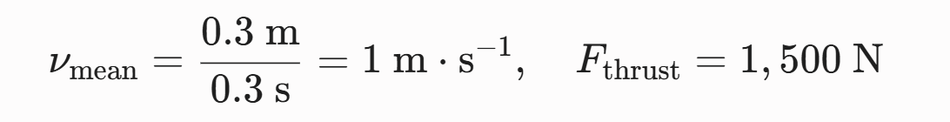
Problem: The packaging machine must push a 1,500 N load along a 300 mm stroke in 0.3 s (mean velocity 1 m/s). The mechanism repeats every second (duty cycle 30%). The design calls for a 24 V supply and minimal maintenance.
Step 1 — Mechanical Requirements:
Step 2 — Choose Transmission:
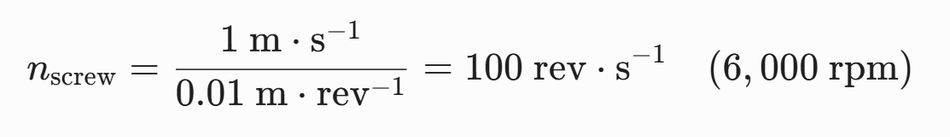
The ball screw is a right choice: high efficiency, high speed, long life. Selecting a 10 mm lead ball screw yields a mechanical rotational frequency of:
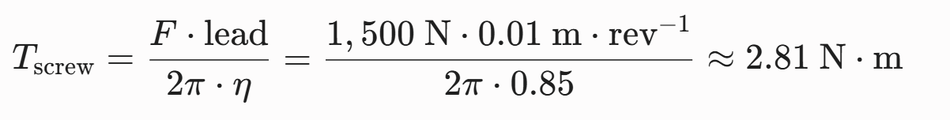
Step 3 — Estimate Torque: With 10 mm lead and 85% screw efficiency, the required input torque at the screw is:
Here, a 3:1 gear reduction means the motor must deliver 0.93 N·m at 3× the speed.
Step 4 — Select Motor Type: Because the system operates at a 30% duty cycle with rapid cycling, a brushless DC (BLDC) or AC synchronous servo motor is chosen. These technologies handle the 0.94 N.m root-mean-square (RMS) torque demand continuously without thermal saturation.
Step 5 — Check Duty Cycle and Environment: 30% duty cycle means the continuous current rating of the servo motor is used. The actuator must be IP65 or higher for possible wash-down.
Other Considerations
Voltage and Current: Match motor voltage to available supply (12/24 V DC or 120/240 V AC). Brushed DC actuators draw high peak currents; servo drives require a stable DC supply.
Feedback Resolution: High-precision applications require encoders or resolvers with sufficient resolution.
Safety and Compliance: Evaluate standards including IEC 60034-30-1 for motor efficiency classes (IE1–IE4), IEC 60529 for IP ratings, ISO 13849 for machine safety, AEC-Q100 for automotive reliability, and IEC 61508 for functional safety.
Applications
Electric linear actuators span industries from factory automation to aerospace. The motor type correlates with application requirements.
Industrial Automation
In industrial automation, linear actuators are used in packaging machines, assembly lines, material handling systems, inspection stations, and automated presses. The servo-based actuators are commonly selected where high speed, repeatable positioning, and continuous operation are required. The ball screw and roller screw mechanisms are preferred for high-force or long-life applications because they provide efficient conversion of rotary motion into linear motion. These systems often integrate with an actuator controller, a PLC, or a motion control network to enable synchronized machine operation.
Automotive and Off-Highway Equipment
In automotive, agricultural, construction, and off-highway vehicles, brushed DC actuators remain common because they are simple, rugged, and cost-effective. They are used for movable steps, hatches, engine covers, seat adjustment, tailgate lifts, and access panels. In these applications, self-locking screw mechanisms, high load capacity, shock resistance, and environmental sealing are important. Suitable IP rating is required to protect the actuator from dust, water, vibration, mud, and temperature variation.
Medical and Laboratory Equipment
Medical devices and laboratory systems use stepper, BLDC, and servo actuators where quiet operation, compact size, and precise positioning are required. Common examples include patient beds, imaging tables, diagnostic equipment, pipetting systems, dosing mechanisms, and small positioning stages. In these applications, smooth motion, low noise, high precision, and reliable feedback are more important than maximum force. Compliance with safety, hygiene, and electrical standards may also be required.
Aerospace and Defense
The aerospace and defense applications require actuators with high reliability, low weight, accurate control, and resistance to harsh environments. Electric linear actuators may be used in UAV mechanisms, aircraft interior systems, control surfaces, sensor positioning, simulation platforms, and subsea or defense equipment. BLDC and servo motors are often preferred for their high efficiency, long service life, and accurate closed-loop motion control.
Robotics and Precision Automation
In robotics, linear actuators are used for grippers, tool changers, collaborative arms, positioning slides, and compact automated mechanisms. Stepper motors are suitable for lower-force positioning, while BLDC and servo systems support faster, smoother, and more dynamic movement. The direct-drive linear motors are used when zero backlash, high acceleration, and micrometre-level positioning are required.
Renewable Energy
Solar tracking and wind turbine pitch control require high reliability in outdoor environments. Actuators for solar arrays prioritize high ingress protection (IP66/IP67) and self-locking screws to resist wind-induced back-driving. In wind turbines, high-force servo actuators with roller screws have increasingly replaced hydraulic systems to reduce maintenance and improve energy efficiency.
Entertainment and Simulation
Training platforms and entertainment simulators require high dynamic responsiveness. The servo-driven actuators provide the continuous duty cycles and high acceleration necessary to replicate realistic motion profiles.
Recommended Reading: What are Pneumatic Actuators? Principles, Types, and Applications
Maintenance and Lifetime Considerations
The choice of motor and transmission affects maintenance requirements and lifetime.
Brushed DC Motors: Brushes wear and must be replaced after tens of thousands of cycles. Duty cycle limitations accelerate the rise in winding temperature. Lubrication of the screw and gearbox is essential.
BLDC Motors: No brushes to wear, but bearings degrade over time. Integrated electronics may limit operating temperature. With proper cooling, BLDC actuators achieve tens of millions of cycles.
Stepper Motors: No brushes; lifetime limited by bearing wear and screw lubrication. Overloading causes missed steps. Closed-loop steppers reduce heat and improve reliability.
Servo Motors: Bearings and encoder components are the main wear parts. Roller screws provide higher life than ball screws but require periodic lubrication.
Linear Motors: Minimal mechanical wear; only linear bearings require maintenance. Maintain the air gap and magnet cleanliness. Cooling systems must be monitored to prevent demagnetization or coil overheating.
Environmental sealing protects against dust and water ingress. IP65 actuators resist low-pressure water jets; IP66 withstands high-pressure spray; IP67 allows 1 m/30 min immersion; IP68 permits continuous immersion. The food-processing actuators may require an NSF-H1 food-grade lubricant and a stainless-steel housing.
Recommended Reading: Stepper vs Servo Motors: Mastering Motor Selection for Precision Engineering
Standards and Trends
Efficiency and Environmental Standards
Motor efficiency and environmental protection are becoming increasingly important in linear actuator design. IEC 60034-30-1 defines efficiency classes for many low-voltage electric motors, commonly identified as IE1, IE2, IE3, and IE4. Higher classes indicate better efficiency, which can reduce heat generation, improve duty cycle, and lower energy consumption in continuous-use actuator systems.
Ingress protection is commonly specified using the IP code defined by IEC 60529. In actuator applications, IP ratings help define resistance to dust and water exposure. For example, IP65 indicates dust-tight protection and resistance to water jets; IP66 improves protection against stronger jets; IP67 allows temporary immersion; and IP68 applies to deeper or longer immersion conditions defined by the manufacturer. Washdown or hygienic environments may require higher protection levels, such as IP69K.
Safety Standards
Machine builders should evaluate actuator safety according to the function being performed. ISO 13849-1 is commonly used for safety-related parts of control systems in machinery, while IEC 61508 provides a broader functional safety framework for electrical, electronic, and programmable electronic systems. In safety-related actuator functions, designers may need redundant feedback, fault detection, braking, safe torque off, overload monitoring, or self-diagnostics.
The application-specific standards may also apply. Automotive actuators may require validation of vibration, temperature, EMC, and reliability. Aerospace systems may require environmental testing, qualified electronics, and strict software or hardware development processes. Medical devices, food-processing machines, and outdoor equipment may introduce additional hygiene, electrical safety, or sealing requirements.
Digital Integration
Modern actuators are increasingly moving from simple motor-driven devices to intelligent motion subsystems. Integrated electronics can combine a motor, actuator controller, drive, feedback sensor, and communication interface into a single compact unit. The common industrial communication options include CANopen, IO-Link, EtherCAT, EtherNet/IP, and PROFINET.
Digital integration enables better synchronization with PLCs, robots, and motion controllers. It also supports condition monitoring by tracking motor current, temperature, position, speed, vibration, and operating cycles. This data can be used for predictive maintenance, helping engineers identify wear, overload, misalignment, lubrication issues, or abnormal duty cycle before failure occurs.
Market Trends
The global linear actuator market is set to reach USD 128.66 billion by 2035. [5] Electric actuators account for 52.54% of this market and grow faster than hydraulic or pneumatic. The ball-screw drives hold 42.54% share; loads between 2–10 kN account for 33.57% of demand. Industry 4.0 adoption, energy-efficiency regulations, and the electrification of machinery and vehicles drive this growth.
Emerging Technologies
More-Electric Aircraft: Replacement of hydraulic actuators with electric reduces weight and maintenance. High-voltage BLDC or brushless AC motors paired with roller screws enable thrusts exceeding 50 kN while meeting aerospace standards.
Smart Actuators: Embedded sensors, IoT connectivity, and edge computing allow actuators to self-optimise and report health. Predictive maintenance reduces downtime.
High-Temperature and Radiation-Tolerant Motors: Nuclear facilities and space require special materials and encapsulation.
Advanced Materials: Carbon fibre-reinforced polymer screws and magnetic composites reduce weight and increase efficiency.
Recommended Reading: Electric Actuator: Comprehensive Engineering Guide
Conclusion
The motor inside a linear actuator dictates the performance envelope of the actuator system. Brushed DC motors offer simplicity and cost advantages but are limited by brush wear and duty cycle. BLDC motors improve efficiency and lifespan and often integrate controllers. Stepper motors provide cost-effective positioning with moderate forces. Servo motors deliver high thrust, speed, and precision for demanding automation. Direct-drive linear motors eliminate mechanical transmission altogether, enabling zero backlash and extreme accuracy.
Engineers must evaluate how motor torque, gear ratio, screw lead, and transmission efficiency combine to produce the required linear motion. Final selection should consider load capacity, stroke length, speed, duty cycle, feedback, IP rating, power supply, and relevant standards. Understanding the linear actuator motor is essential for designing reliable, efficient, and application-specific motion systems.
Frequently Asked Questions (FAQs)
Q. What is a linear actuator motor?
A. The linear actuator motor is the electric motor inside a linear actuator that generates rotary motion. This motion is converted into straight-line travel through a lead screw, ball screw, belt, or gear mechanism for various applications.
Q. What is the difference between DC and AC linear actuator motors?
A. DC motors are simple, compact, and common in low-duty actuator systems. AC and BLDC servo motors provide smoother control, higher efficiency, and longer service life, making them suitable for automation, industrial machinery, and precision motion systems.
Q. How do I choose a motor type for an electric linear actuator?
A. Start with force, speed, stroke length, duty cycle, accuracy, and available power supply. Brushed DC suits simple systems, stepper motors suit positioning, while BLDC and servo motors support high-performance automation and heavy-duty actuator requirements.
Q. Brushed DC versus BLDC: which is better for actuators?
A. Brushed DC motors are cheaper and easier to control, but brushes wear over time. BLDC motors offer better efficiency, durability, and speed control, making them better for long-life systems, robotics, medical devices, and high-quality actuator designs.
Q. Stepper versus servo linear actuators: when to use each?
A. Stepper actuators are best for cost-effective positioning where loads are moderate, and speeds are controlled. Servo actuators are better for high-speed, high-force, continuous-duty-cycle, and closed-loop precision in industrial automation or robotics.
Q. How long do linear actuator motors last?
A. Service life depends on motor type, load, duty cycle, lubrication, and operating environment. Brushed motors wear faster, while BLDC and servo motors last longer. Proper cooling, load control, and maintenance improve actuator durability significantly.
Q. What are smart actuators with integrated motors?
A. Smart actuators combine the motor, gearbox, feedback sensors, actuator controller, and communication electronics in one unit. They support remote control, diagnostics, position monitoring, and predictive maintenance for automation, home automation, and connected machine designs.
References
[1] Linak. LA36 — Industrial Actuator: Product datasheet [Cited 2026 May 31]; Available at: Link
[2] Firgelli Automations. How Strong Are Linear Actuators? Force & Capacity Guide [Cited 2026 May 31]; Available at: Link
[3] Firgelli Automations. Leadscrew Types: Acme vs Ball Screw vs Roller Screw [Cited 2026 May 31]; Available at: Link
[4] Analog Devices. Understanding Microstepping in Motion Control [Cited 2026 May 31]; Available at: Link
[5] Precedence Research. Linear Actuator Market Size, Share and Trends 2026 to 2035 [Cited 2026 May 28]; Available at: Link
in this article
1. Key Takeaways2. Introduction3. What is a Linear Actuator Motor?4. Motor Topologies in Linear Actuators5. How Motor Choice Drives Actuator Force, Speed, and Duty Cycle?6. Transmission Pairing7. Feedback and Control Architectures8. Selection Criteria and Sizing Methodology9. Applications10. Maintenance and Lifetime Considerations11. Standards and Trends12. Conclusion13. Frequently Asked Questions (FAQs)14. References