Electric Actuator: Comprehensive Engineering Guide
This article details electric actuators — explaining theory, construction, motor topologies, transmission trade offs, feedback architectures, selection methodology, applications, comparisons with fluid power, maintenance and standards.

01 Jun, 2026. 14 minutes read
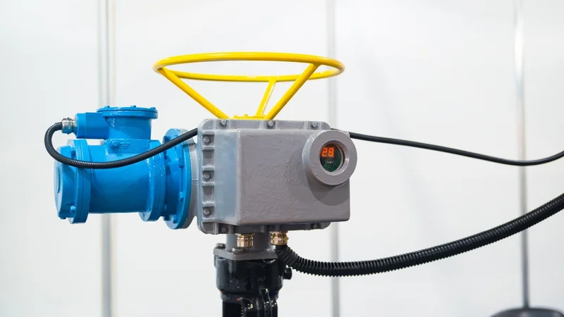
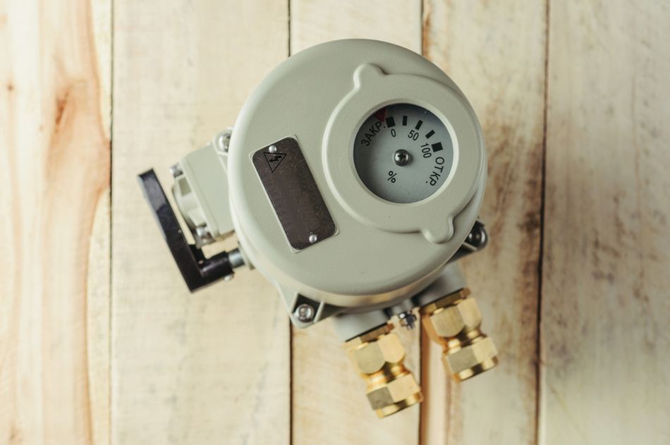
Multi-Turn Electric Actuator for Pipeline Control in Nuclear, Explosion-Proof and Industrial Versions
Key Takeaways
Definition and Core Subsystems – Electric actuators integrate a motor, transmission, and feedback into a ready‑to‑use linear or rotary drive; they provide precise motion control and eliminate fluid leaks.
Performance Envelopes – The vendors publish wide performance envelopes: compact actuators like Maxon 16 mm 24 V unit deliver 403 N force, while heavy‑duty roller‑screw units such as Tolomatic RSX achieve 222 kN continuous force.
Mechanical Efficiency – Efficiency varies with technology — ball‑screw systems reach 90%+, lead‑screws offer 20–80% with self‑locking, rack‑and‑pinion drives approach 98.5%, whereas pneumatic systems are 10–20% efficient.
Thermal and Duty Cycle Limits – Duty cycle is critical: many medical actuators have a 10% duty cycle (2 min on, 18 min off), while industrial roller‑screw actuators support a 100% duty cycle.
Environmental and Automotive Ratings – IP protection levels range from IP40 for clean environments to IP69K stainless‑steel actuators suitable for wash‑down; seat drives in cars use 12 V or 24 V motors with torques up to 45 Nm and optional Hall sensors.
Fluid Power Comparison – Electric actuators typically operate at 75–80% efficiency, whereas pneumatic cylinders are 10–20% efficient and hydraulic systems are about 50%, leading to significant energy savings when converting from fluid power.
Future Aerospace and Networking Trends – Emerging trends include more‑electric aircraft — e.g., the Boeing 787 uses electromechanical actuators (SEMA) to control two of its seven spoiler pairs — as well as network‑connected actuators using CANopen, EtherCAT, and IO‑Link for predictive maintenance.
Introduction
The electric actuators convert electrical energy into controlled mechanical motion. They integrate a motor, motion‑conversion mechanism, feedback sensors and a housing into a compact unit that can produce linear or rotary displacement. Unlike bare motors, which simply rotate a shaft, an electric actuator delivers usable force and stroke along a defined path with precision and repeatability. Their ability to precisely control position, speed and force, combined with high energy efficiency and minimal maintenance, has made them the default choice for modern automation.
Depending on the application, an electric actuator may use DC motors, stepper motors, servo motors, gearboxes, lead screws, ball screws, sensors, and control electronics to achieve controlled force, speed, stroke length, and feedback. This article details electric actuators — explaining theory, construction, motor topologies, transmission trade‑offs, feedback architectures, selection methodology, applications, comparisons with fluid power, maintenance and standards.
What Is an Electric Actuator?
The bare motor provides torque and speed, yet lacks the mechanical interface needed for useful linear motion. The electric actuator solves this by combining the motor with a transmission mechanism, such as a lead screw, ball screw, gearbox, bearings, seals, limit switches, and feedback sensors inside a compact protective housing. This integrated design converts motor rotation into precise linear motion, allowing engineers to achieve controlled force, speed, and stroke length without designing a custom motion assembly from scratch.
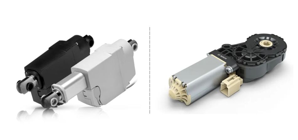
For example, the LA23 medical actuator by Linak packages a 12 V or 24 V DC motor, lead‑screw drive and limit switches into a waterproof housing that delivers up to 2.5 kN push/pull force and strokes from 20 mm to 500 mm. [1] In vehicles, the AHC2‑FL seat drive by Bosch combines a compact DC motor with planetary gears and optional Hall sensors, delivering up to 45 Nm torque from a 12 V or 24 V supply. Electric actuators therefore provide plug and play motion while hiding the complexity of mechanical conversion.
Recommended Reading: What is an Actuator? Types, Principles, and Applications
How an Electric Actuator Works?
The electric actuator works by converting electrical energy into controlled mechanical movement. In most designs, an electric motor first generates rotary motion, which is then converted into linear motion or controlled rotary motion through an internal transmission system. The actuator's performance depends on how its motor, motion converter, sensors, control electronics, and mechanical interfaces work together.
The main subsystems include:
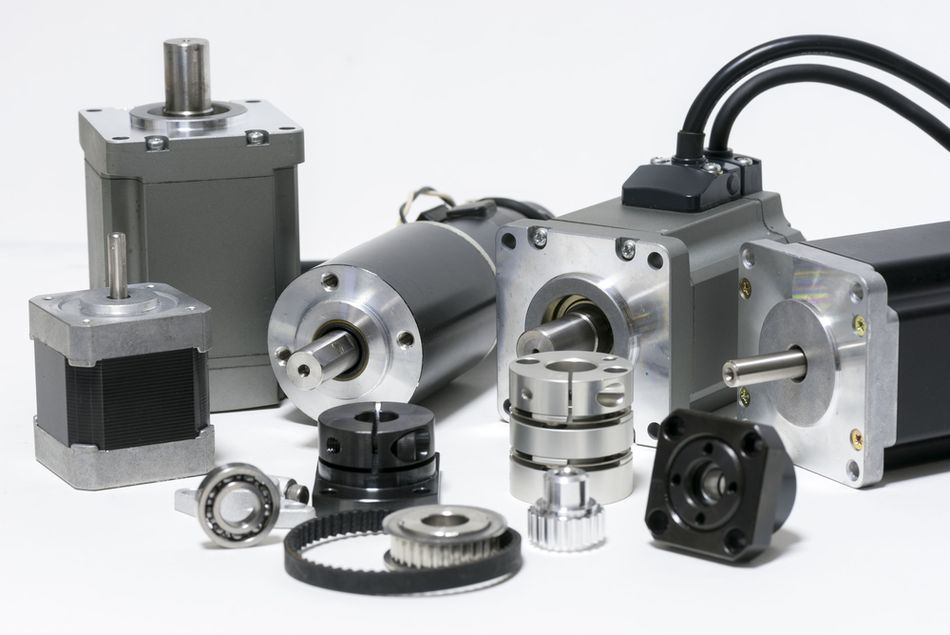
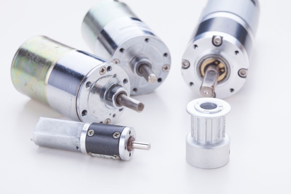
Motor — the prime mover. Options include brushed DC motors for simplicity, brushless DC (BLDC) motors for long life, steppers for open‑loop positioning, AC servo motors for high speeds, and linear motors for direct drive.
Transmission or Motion Converter — converts rotary motion into linear or rotary output through screws, belts, gears or direct electromagnetic thrust. This determines force capability, efficiency and self‑locking behaviour.
Feedback Sensors — limit switches provide end‑of‑travel stops; potentiometers or Hall sensors measure relative position; encoders (incremental or absolute) enable closed‑loop servo control. Linear encoders or LVDTs give micrometre‑level feedback.
Control Electronics — a drive or amplifier regulates current and voltage based on command signals. Integrated controllers implement trapezoidal, sinusoidal or field‑oriented control, monitor temperature and implement safety functions.
Mechanical Interface — clevises, trunnions, flanges or threaded ends connect the actuator to the load. Bearings, seals and wipers protect internal components against dust, liquids and side loading.
The typical electric actuator architecture includes the motor, transmission, feedback sensors, controller, power cables, and communication interface. [2] In networked systems, protocols such as CANopen, EtherCAT, or Modbus allow multiple actuators to operate under coordinated motion control.
Recommended Reading: Motor Control Design: End-to-End Methodology
Motor Topologies and Trade‑offs
Electric actuators use several motor types. The choice influences cost, efficiency, torque density and control complexity.
Brushed DC Motors
Simple and inexpensive, brushed DC motors use mechanical commutators and brushes. They provide high starting torque and are easy to drive with basic H‑bridge circuits. However, brush wear limits life and generates electromagnetic noise. Many low‑cost linear actuators and automotive seat drives use brushed DC motors operating at 12 V or 24 V. Duty cycles are typically below 10% in these applications.
Brushless DC (BLDC) Motors
Brushless motors employ electronic commutation via Hall sensors or encoders. They offer higher power density, longer life and improved efficiency over brushed designs. Maxon's 16 mm BLDC actuator integrates a 60 W 24 V BLDC motor with a ball screw, providing 403 N force and accelerating to 12, 000 rpm in <2 ms, with an integrated digital encoder for precise positioning. [3] BLDC actuators are common in robotics, medical devices and industrial automation.
Stepper Motors
Stepper actuators use permanent‑magnet or hybrid stepper motors. They move in discrete steps (e.g., 1.8° per step) and can hold position without feedback. Steppers excel at low‑speed positioning but lose torque at high speeds and vibrate due to the discrete stepping. Closed‑loop steppers with encoders mitigate these effects and can reach 1 kHz update rates.
AC and DC Servo Motors
Servo actuators combine high‑performance AC or DC motors with feedback and servo drives. They provide smooth motion, high speeds and continuous force. For example, Thomson's PC25 precision actuator uses a ball‑screw driven by a servo motor to achieve 1.33 m/s linear speed, 10 m/s² acceleration and repeatability of ±0.01 mm. Servo actuators are suited to machine tools, packaging and pick‑and‑place equipment.
Linear Motors
Linear motors generate thrust directly without conversion mechanisms. They can be coil‑and‑magnet assemblies (iron core or ironless) or tubular motors. Linear motors deliver very high speeds and acceleration but produce lower continuous force per unit volume. Their elimination of screws and gears removes backlash and wear, making them ideal for high‑precision stages but requiring closed‑loop control and careful thermal design.
Recommended Reading: Stepper vs Servo Motors: Mastering Motor Selection for Precision Engineering
Transmission and Motion Conversion
The transmission converts motor torque into linear or rotary movement. Selection affects efficiency, back‑drive capability and life.
Lead Screws
Lead (Acme) screws have a trapezoidal thread profile and sliding contact between the screw and nut. Friction results in efficiencies ranging from 20% to 80% depending on the helix angle. High friction produces self‑locking behaviour: when efficiency falls below ~50%, the screw will not back‑drive, allowing lead‑screw actuators to hold position without power. They are cost‑effective and provide moderate accuracy but wear faster than ball or roller screws. Linak LA23 uses a lead screw with built‑in overload clutch and offers strokes up to 500 mm.
Ball Screws
Ball screws employ recirculating ball bearings between screw and nut, reducing friction and yielding efficiencies above 90%. This high efficiency enables higher speeds and duty cycles; however, ball screws readily back‑drive and therefore require brakes or holding power. Festo EPCC electric cylinders use ball screws and provide feed forces from 75 N to 1 000 N, speeds up to 0.6 m/s, acceleration 15 m/s², repeatability ±0.02 mm, and 100% duty cycle. [4] Parker ETH actuators combine ball screws with anti‑rotation guides to achieve speeds of up to 1.7 m/s and strokes up to 1,600 mm.
Planetary Roller Screws
Roller screws replace balls with threaded rollers that engage the screw, increasing contact points and load capacity. They offer the highest force density and long life. Tolomatic RSX extreme‑force actuators use planetary roller screws to deliver forces up to 222 kN and support 100% duty cycle. Roller screws suit pressing, forming and heavy‑duty applications but are more costly.
Belts and Pulleys
Timing belts provide long strokes and high speeds at moderate cost. They are common in gantry axes and packaging machines but exhibit elastic stretch and lower stiffness. Belts cannot hold position without power and may require tensioning. Efficiency is high but less than rack‑and‑pinion.
Rack‑and‑Pinion
Rack‑and‑pinion systems combine a round pinion gear with a linear rack. Modern designs achieve up to 98.5% efficiency and backlash below 1 arc‑minute. [5] They offer unlimited stroke lengths and high load capacity. Rack drives are often servo‑driven and used in long‑travel gantries.
Worm Gears
Worm gear drives provide large reduction ratios in a compact package. Efficiency ranges from 30% to 90% depending on the lead angle and lubrication. Once the friction angle exceeds the lead angle, worm gears become self‑locking, enabling hold position without power. Lower friction increases efficiency but removes self‑locking. Worm gears are common in low‑speed rotary actuators and seat adjustment motors.
Direct‑Drive Linear Motors
Eliminating transmission components yields zero backlash and infinite resolution. Linear motors excel at high‑speed, high‑precision motion but have lower force density and require sophisticated controls. They are used in wafer steppers, pick‑and‑place machines and high‑end robotics.
Recommended Reading: Motion Control in Robotics: 4 Types of Motors for Industrial Robots
Feedback and Control Architectures
Accurate positioning requires appropriate feedback. Electric actuators use various sensing methods:
Limit Switches provide simple end‑of‑stroke signals and protect against over‑travel.
Potentiometers offer analog voltage proportional to position. They are low cost but susceptible to wear.
Hall‑Effect Sensors detect magnetic fields; they often serve commutation in BLDC motors or provide incremental position counts.
Encoders convert motion to digital pulses. Incremental encoders provide counts per revolution; absolute encoders output a unique code for each shaft angle. The resolutions range from 100 counts/rev to 20,000 counts/rev or more.
Linear Encoders or LVDTs mount directly along the travel path for micrometre accuracy; they are used in precision stages and machine tools.
Feedback signals feed into drive electronics. Modern actuators integrate CANopen, EtherCAT, IO‑Link or PROFINET interfaces, enabling plug‑and‑play network configuration, diagnosis and predictive maintenance. In high‑performance applications, real‑time fieldbus networks coordinate multi‑axis motion and enable safe torque-off (STO) functions per ISO 13849 requirements. [6]
Recommended Reading: Types of Industrial Control Systems: Examples and Applications
Selection Criteria and Sizing
Choosing the right electric actuator requires matching the device to the application's force, stroke, speed, duty cycle, environment and regulatory constraints. The key criteria include:
Force and Load
Calculate the required linear force from the load mass and desired acceleration: F = m x a + F (friction). Include static friction, incline effects and safety factors. Ball‑screw actuators like Parker ETH supply dynamic loads up to 125 kN and speeds 1.7 m/s, while roller‑screw units such as Tolomatic RSX handle 222 kN. For small loads, Festo EPCC covers 75–1 000 N.
Stroke and Speed
Define the linear travel. Screw actuators offer strokes from a few millimetres to 1,500 mm. Belt and rack systems can extend indefinitely. Ball‑screw speeds can reach 1.7 m/s; lead‑screw speeds are lower due to friction. For very high speeds, consider belt or linear motor solutions.
Duty Cycle
Duty cycle is the percentage of time the actuator is energized over a period. Many medical and consumer actuators are rated at 10% duty cycle — e.g., the Linak LA23 runs for 2 min on and 18 min off. Industrial roller‑screw actuators support 100% duty cycle. Selecting a unit with a duty cycle higher than the application prevents overheating.
Accuracy and Repeatability
Precision depends on screw pitch, backlash and feedback resolution. Thomson PC25 achieves ±0.01 mm repeatability; Festo EPCC offers ±0.02 mm; Ewellix CASM reaches ±0.01 mm. For micrometre‑level positioning, use linear encoders or direct‑drive motors.
Environment and Protection
IP ratings specify dust and water protection. IEC 60529 defines that the first digit indicates solids protection (6 means dust‑tight) and the second digit indicates water ingress (5 means protection against water jets). A typical IP65 actuator resists dust and low‑pressure water but not immersion; IP69K stainless‑steel units like Festo EPRF withstand high‑pressure washdown and deliver up to 12.5 kN force.
Voltage and Certifications
Identify supply voltage (e.g., 12 V or 24 V DC for automotive; 48–400 V for industrial). Medical actuators must comply with IEC 60601‑1; automotive electronics follow AEC‑Q100; industrial safety functions adhere to ISO 13849; aerospace actuators must meet DO‑160 environmental tests such as temperature extremes, vibration and waterproofness. Ensure the actuator's certifications match the application.
Worked Sizing Example
Suppose a machine must press a 5 kN force over a 300 mm stroke at 0.5 m/s with continuous duty. A ball‑screw actuator would require a screw pitch providing at least 5 kN thrust. Checking vendor data, Parker ETH offers an ETH125 frame capable of up to 56 kN and speeds above 1 m/s, making it suitable. A roller‑screw could be selected for higher cycle life. Provide a 20–30% safety margin and verify that the duty cycle rating is 100%. Select an IP65 version if wash‑down is needed. Choose a servo motor and drive that deliver at least 5 kN × 0.5 m/s = 2.5 kW mechanical power, then add gear ratio and motor speed margin.
Recommended Reading: Actuator Motor: Differences Between Actuators and Motors, Selection, and Applications
Applications across Industries
Electric actuators are useful; the following examples illustrate their diversity.
Industrial Automation
In factories, electric actuators position parts, tools and sensors with millimetre precision. Thomson PC25 actuators provide ±0.01 mm repeatability, 1.33 m/s speed and 1 250 N dynamic load, making them ideal for packaging and pick‑and‑place. Tolomatic RSX roller‑screw units deliver forces up to 222 kN for pressing, metal forming and injection moulding. Festo's EPCC and EPRF cylinders cover precise handling and hygienic food processing, with feed forces from 75 N to 12.5 kN and IP69K protection.
Automotive
Modern vehicles employ dozens of electric actuators for seats, steering and powertrain functions. Bosch's AHC2‑FL seat drive integrates a 12/24 V motor, planetary gear, and optional Hall sensors; it delivers up to 45 Nm of torque and compact packaging for seat forward/back, height, and recliner adjustments. Electric throttle valves, electronic parking brakes and active aerodynamic flaps use similar actuators. Europe's automotive electric actuator market is growing at ≈5.3 % CAGR as vehicles adopt power‑by‑wire systems for energy efficiency and autonomous features.
Medical and Healthcare
Hospital beds, patient lifts and surgical equipment rely on quiet, hygienic actuators. Linak LA23 medical actuators provide up to 2.5 kN of force, strokes of 20–500 mm, IPX4/IPX6/IPX6W protection, and IEC 60601‑1 approvals. They integrate limit switches and an optional potentiometer and have a 10% duty cycle to prevent overheating. Stainless‑steel actuators like Festo EPRF with IP69K rating are used in cleanrooms and operating theatres.
Aerospace
Electromechanical actuators are key enablers of more‑electric aircraft. On the Boeing 787, spoiler electromechanical actuators (SEMAs) control two of the seven spoiler pairs, providing roll control, speedbrake and droop functions; this marks the first use of an electromechanical actuator on a primary flight control surface of a civil transport aircraft. Curtiss‑Wright Exlar actuators are used in commercial engines and control surfaces, offering energy savings — electric servo systems are ~80% efficient compared with 50% for hydraulic systems. Spacecraft use radiation‑hardened linear actuators for solar array deployment and antenna pointing.
Robotics and Automation
Cobots and industrial robots require compact, high‑precision actuators. BLDC and servo actuators with harmonic gears deliver high torque density and back‑driveability. Linear actuators with ball screws power grippers and z‑axes in pick‑and‑place robots. Integrated servo actuators with EtherCAT or PROFINET interfaces enable coordinated multi‑axis motion for assembly lines.
Renewable Energy
Solar trackers and wind turbines employ electric actuators to position photovoltaic panels and blade pitch. Ball‑screw actuators with IP66 protection provide reliability in outdoor environments. Some solar actuators incorporate self‑locking lead screws to hold panels against wind loads without continuous power. The adjustable pitch actuators in wind turbines reduce yaw misalignment and optimize output.
Recommended Reading: Robot Actuators: A Comprehensive Guide to Types, Design, and Emerging Trends
Maintenance and Lifetime
Electric actuators require minimal maintenance compared with fluid power systems.
But they still need attention to ensure long life:
Cycle Life — High‑quality actuators achieve 10,000–50,000 cycles when operated within the rated load and duty cycle; operating at 50% of rated load can extend life beyond 100,000 cycles. Operating near maximum capacity may reduce life to a few thousand cycles.
Lubrication — The ball and roller‑screw units require periodic lubrication via grease fittings. Festo and Parker actuators integrate lubrication ports for convenient servicing.
Alignment and Side Loading — Avoid misalignment and side loads; these cause premature wear on seals, screws and bearings. Electric actuators often include anti‑rotation guides to handle minor side loads.
Environmental Protection — Ensure seals and wipers remain intact. For wash‑down areas, use IP65 or IP69K units. Inspect cable glands and connectors for damage.
Electronics — Monitor temperature and current to prevent overheating. Many actuators integrate thermal sensors and over‑current protection.
The common failure modes include screw or nut wear, bearing failure, motor winding overheating and sensor failure. Scheduled inspections and adherence to duty cycle ratings minimize unplanned downtime.
Standards and Compliance
Electric actuators must comply with multiple standards depending on their application:
IEC 60034‑30‑1 — This standard defines energy efficiency classes for AC motors, typically from IE1 to IE4. For actuator systems using AC motors, higher-efficiency motor classes can reduce electrical losses, improve energy efficiency, and support long-term sustainability goals in industrial automation.
IEC 60529 — This standard defines IP ingress protection ratings for electrical enclosures. For example, IP65 indicates dust-tight protection and resistance to water jets, while IP69K is suitable for high-pressure washdown environments. This is important for outdoor, food-processing, medical, and heavy-duty actuator applications.
ISO 13849 — This standard addresses the safety of machinery control systems. Performance Levels from PLa to PLe define the reliability of safety-related control functions. In actuator systems, functions such as emergency stop, overload protection, safe direction control, or Safe Torque Off may need to meet the required performance level based on machine risk assessment.
IEC 60601‑1 — This standard governs the basic safety and essential performance of medical electrical equipment. Electric linear actuators used in hospital beds, patient lifts, treatment chairs, and rehabilitation systems must meet strict requirements for electrical safety, mechanical reliability, leakage current, and patient protection.
AEC‑Q100 — This automotive qualification standard applies to integrated circuits used in vehicle electronics. Actuator control circuits, position feedback electronics, Hall sensors, and embedded drivers used in automotive seat adjustment, throttle control, mirrors, and active aerodynamic systems may require AEC-Q100-qualified components.
DO‑160 — RTCA environmental tests for airborne equipment. Sections cover temperature, altitude, humidity, shock, vibration, waterproofness, sand/dust, fungus, salt spray, magnetic effects and power input; aerospace actuators must demonstrate resilience under these conditions.
Understanding and applying these standards ensures actuators meet safety, environmental and regulatory requirements across industries.
Conclusion
Electric actuators combine motors, mechanical conversion systems, feedback sensors, and control electronics into compact assemblies that deliver precise linear or rotary motion. With advances in ball screw technology, BLDC motors, and smart actuator controls, modern designs can achieve high force, long stroke lengths, high-speed movement, and reliable position feedback. The applications include industrial automation, robotics, automotive, and material-handling.
Compared with pneumatic and hydraulic systems, electric actuators generally offer better energy efficiency, cleaner operation, easier integration, and improved sustainability. Proper selection requires balancing load capacity, speed, duty cycle, precision, mounting conditions, and environmental protection. The electric actuators will remain essential for efficient, programmable, and connected electromechanical movement.
Frequently Asked Questions (FAQs)
Q. What is an electric actuator?
A. The electric actuator is an electromechanical device that converts electrical energy into controlled linear or rotary motion. It combines a motor, transmission, housing, sensors, and controls to deliver precise movement without hydraulic fluid, compressed air, or complex external mechanics.
Q. How does an electric actuator work?
A. The electric actuator uses an electric motor to generate rotation. A lead screw, ball screw, gearbox, or belt then converts this energy into straight line movement or rotary motion, while sensors and controllers regulate position, speed, and force.
Q. How do electric actuators compare with hydraulic and pneumatic actuators?
A. Electric actuators provide cleaner operation, better positioning accuracy, and higher energy efficiency than many hydraulic or pneumatic systems. Pneumatic actuators depend on compressed air and flow control, while hydraulic units provide high force but require fluid maintenance.
Q. Can electric actuators hold position without power?
A. Some electric actuators can hold position without power if they use self-locking lead screws or worm gears. Ball screw and belt-driven actuators may back-drive, so they often need brakes, advanced control, or holding current.
Q. What is the typical lifetime of an electric actuator?
A. The lifetime of an electric actuator depends on load capacity, duty cycle, alignment, contamination, and operating environment. A heavy duty linear actuator usually lasts longer when properly mounted, lubricated, and operated below its maximum rated force.
Q. How do I choose the right IP rating for an electric actuator?
A. Choose the IP rating based on dust, water, cleaning, and outdoor exposure. Indoor systems may need basic protection, while washdown, automotive, or heavy-duty environments often require sealed housings, corrosion-resistant materials, and secure mounting brackets.
Q. What are the advantages of AC versus DC electric actuators?
A. DC actuators, including 12V and 24V DC models, are compact and common in mobile, automotive, and battery-powered systems. AC actuators suit higher-power industrial applications, especially where continuous operation, advanced control, and longer cable runs are required.
References
[1] Linak. Linear Actuator LA23 Data Sheet [Cited 2026 May 28]; Available at: Link
[2] IQS Directory. Types, Applications, and Benefits for Electric Actuators [Cited 2026 May 28]; Available at: Link
[3] Maxon Group. BLDC Motors with Ironless or Iron Core Winding [Cited 2026 May 28]; Available at: Link
[4] Festo. Electric cylinder EPCC [Cited 2026 May 28]; Available at: Link
[5] Tech Rxiv. Bi-directionally Efficient, Backdrivable Gearbox with Low Backlash for Robot Actuators [Cited 2026 May 28]; Available at: Link
[6] ISO. ISO 13849-1:2015 - Safety of Machinery [Cited 2026 May 28]; Available at: Link
in this article
1. Key Takeaways2. Introduction3. What Is an Electric Actuator?4. How an Electric Actuator Works?5. Motor Topologies and Trade‑offs6. Transmission and Motion Conversion7. Feedback and Control Architectures8. Selection Criteria and Sizing9. Applications across Industries10. Maintenance and Lifetime11. Standards and Compliance12. Conclusion13. Frequently Asked Questions (FAQs)14. References