NTC Thermistor: How It Works, Key Specs, and Circuit Design
NTC thermistor is a ceramic resistor whose resistance falls sharply as it warms. This guide covers what sets its curve, how to read R25, B value, and dissipation constant on a datasheet, how to design a sensing divider with real numbers, and how to size an NTC inrush current limiter.

30 Dec, 2024. 14 minutes read
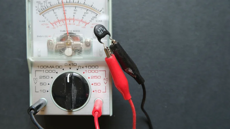
The Value of a NTC Thermistor Being Measured with an Ohmmeter
Key Takeaways
Negative Temperature Coefficient Behavior – NTC thermistor is a thermally sensitive semiconductor resistor whose resistance decreases as temperature rises, typically by 2%/K to 6%/K.
Specifications Beyond Nominal Resistance – Selecting an NTC thermistor requires matching nominal resistance, beta value, tolerances, and thermal characteristics to the intended application and accuracy requirements.
Voltage Divider Linearization – For a divider, setting the series resistor to the geometric mean of the minimum and maximum resistance linearizes output, while powering the circuit from the ADC reference ensures a ratiometric measurement.
Ratiometric Sensing Circuits – Powering the thermistor divider from the ADC reference reduces sensitivity to shared voltage variations, while resistor selection determines the available measurement span.
Managing Sensor Self-Heating – Measurement current generates heat that can distort temperature readings; limiting excitation power and considering dissipation characteristics helps maintain accuracy under operating conditions.
Inrush Current Limiting – Select power thermistors according to capacitance capability, continuous current, ambient temperature, and initial resistance, allowing sufficient cooling between starts to restore protection.
Introduction
In many applications, the NTC thermistor (negative temperature coefficient thermistor) is the most widely used thermistor type, known for low cost and versatility. It handles temperature measurement and thermal protection and also serves as an inrush current limiter in power supply circuits. NTC thermistors are thermally sensitive semiconductor resistors that decrease resistance as temperature increases.
Selecting an NTC thermistor involves more than choosing a nominal resistance. Resistance tolerance, beta value, operating temperature range, thermal response time, and dissipation characteristics all influence measurement accuracy and circuit performance. Practical considerations such as component placement, excitation current, and self-heating compensation are equally important.
This article explains how NTC thermistors operate, what shapes their curves, how to read R25, B value, and dissipation constant on a datasheet, how to design a sensing divider with real numbers, and how to size an NTC inrush current limiter.
What Is an NTC Thermistor?
NTC thermistor changes resistance for two reasons: a change in ambient temperature, or self-heating from its own current. Temperature sensors operate at low current, where only ambient temperature matters; inrush current limiters and liquid level sensors operate in the self-heated region. [1] The opposite device, the PTC thermistor, has a positive temperature coefficient: its resistance rises with temperature. [3]
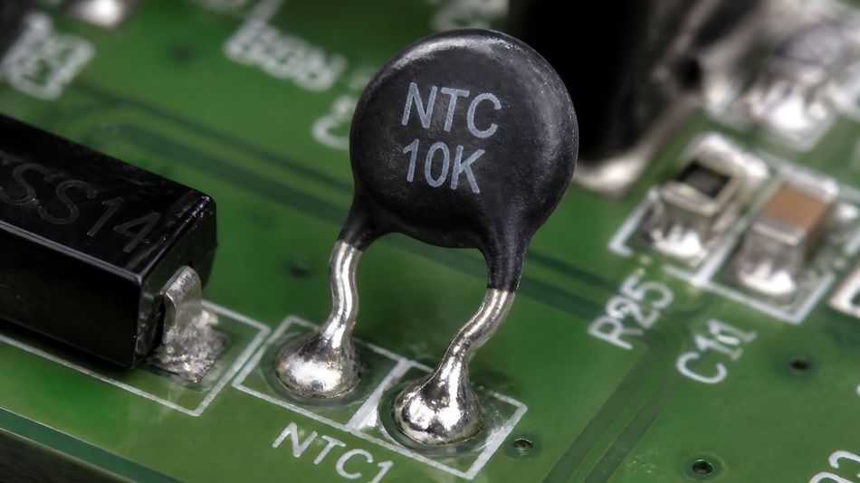
Directly heated NTC thermistors are standardized in IEC 60539-1:2022, which covers parts "typically made from transition metal oxide materials with semiconducting properties" and defines their terms, inspection procedures, and test methods. [2]
Recommended Reading: Thermistor: How It Works, Types, Equations and Uses
How an NTC Thermistor Works?
Spinel Ceramics and Hopping Conduction
NTC thermistor operates on the principle that its electrical resistance decreases as its temperature rises. A widely used material is spinel-type nickel manganite, such as NiMn₂O₄, a semiconducting ceramic in which electrical conduction occurs through thermally activated charge transport.
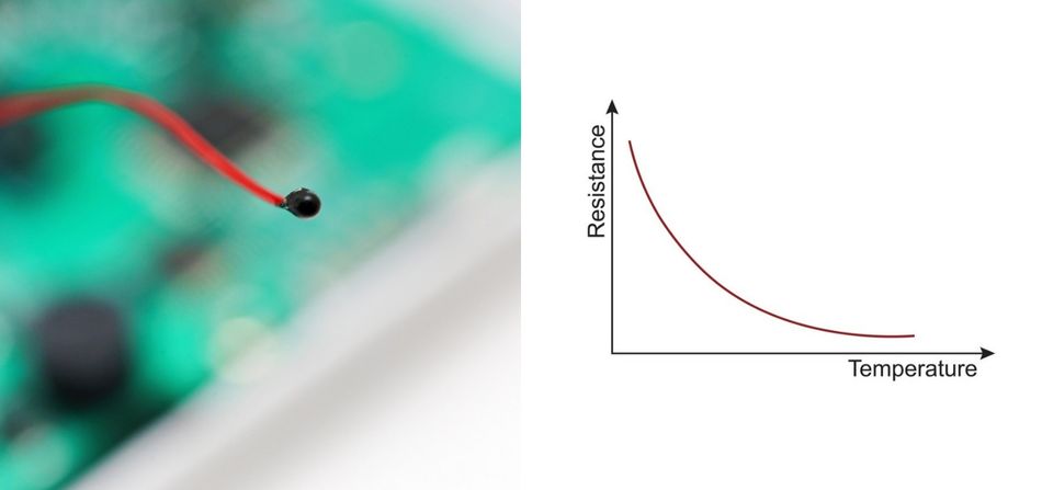
In these materials, small-polaron hopping allows charge carriers to move between neighbouring ions with different oxidation states. Increasing temperature supplies the thermal energy needed for this movement, increasing conductivity and reducing resistance.
Over a limited temperature range, this behaviour can be approximated by an exponential relationship:

where E(A) is the activation energy, and k(B) is Boltzmann's constant; the ratio EA/kB is the B constant.
The oxides of manganese, iron, cobalt, nickel, copper and zinc are used as starting materials, formed into disks, chips or multilayer surface-mount parts and sintered at 1000 °C to 1400 °C. Most thermistor ceramics change resistance over time and under thermal stress, usually upward, and TDK ages its parts after manufacture, so their electrical values stay stable. [1]
Construction Types
The package sets the temperature response of NTC thermistor resistors, how much heat they shed, and how hot they can run.
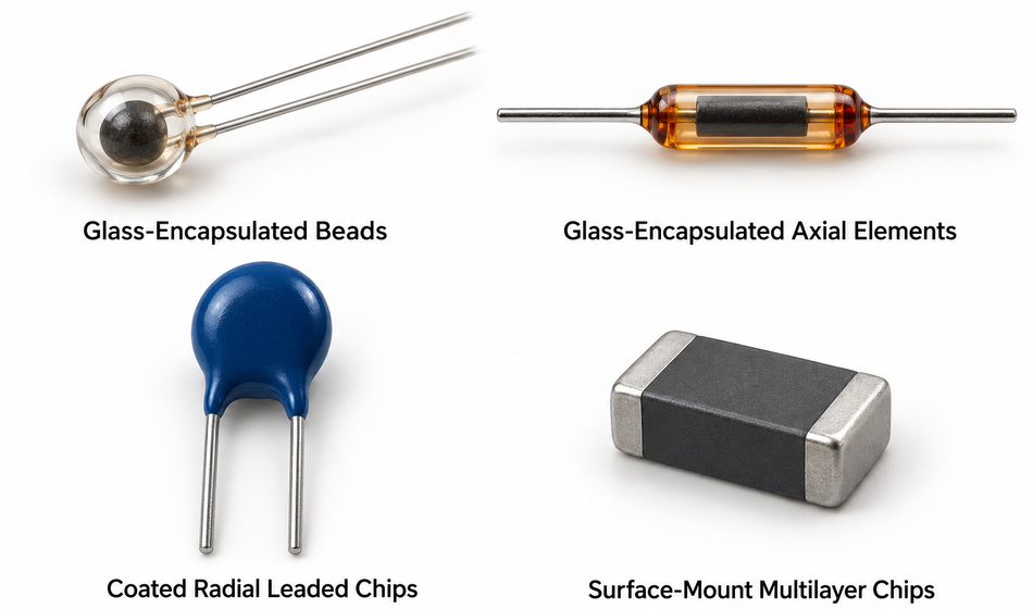
Glass-Encapsulated Beads: These provide high stability and suit precision temperature measurement. The measurement-grade beads cover approximately −80 °C to 300 °C, depending on the device. [5]
Glass-Encapsulated Axial Elements: These combine environmental protection with leads extending from opposite ends. The TDK NTCD series operates from −40 °C to 250 °C, with tin-plated versions limited to 160 °C. Specified dissipation constants are 1–2 mW/°C, with maximum thermal time constants of 10–20 seconds in still air, depending on the variant. [6]
Coated Radial Leaded Chips: These offer a practical construction for general temperature sensing. The Vishay NTCLE100E3 operates from −40 °C to 125 °C, with exposure to 150 °C permitted for limited periods. Its stated dissipation constant is 7 mW/K, and its thermal time constant is 15 seconds. [7]
Surface-Mount Multilayer Chips: These compact devices integrate directly onto PCBs. Their operating limits depend on the individual part, while their thermal behaviour also depends on board layout and mounting conditions. [1]
Glass encapsulation is particularly useful in demanding thermal and humid environments. Epoxy-encapsulated devices generally have lower temperature limits, typically around 150 °C. Always compare thermal specifications under equivalent test conditions, since airflow, mounting, and the surrounding medium affect both dissipation and response time. [5][6]
Recommended Reading: How are Semiconductors Made? Comprehensive Guide to Semiconductor Manufacturing
Key NTC Thermistor Specifications
Selecting an NTC thermistor requires evaluating both its electrical characteristics and thermal behaviour. The following specifications determine its suitability for temperature sensing or current-limiting applications.
Resistance at 25 °C (R₂₅) and Resistance Tolerance: R₂₅ is the zero-power resistance at 25 °C, measured with negligible self-heating. The stated resistance tolerance applies at this reference temperature. For example, the Vishay NTCLE100E3 series offers values from 3.3 Ω to 470 kΩ, with tolerances of ±2%, ±3%, or ±5%, depending on the part. [1]
Beta Value (B₂₅/₈₅ or B₂₅/₁₀₀): The beta value characterizes the resistance–temperature relationship between two specified temperatures. It is expressed in kelvin and depends on the ceramic composition. The Vishay NTCLE100E3 series includes beta values from 2880 K to 4570 K, with tolerances ranging from ±0.5% to ±3%. [7]
Dissipation Constant (δₜₕ): Also called the dissipation factor, this is the power required to raise the thermistor’s body temperature by 1 K above its surroundings at steady state. Typical examples are 1 mW/K for a small glass element in still air and 7 mW/K for a coated radial part. This parameter depends on mounting and environmental conditions. [6]
Thermal Time Constant (τ): This is the time required to complete 63.2% of the total temperature change following a temperature step. Examples include 10 seconds maximum for a small glass element in still air and 15 seconds for a coated radial part. The latter also specifies an approximately 1.2-second response in oil, illustrating the influence of the surrounding medium. Response-time values should only be compared when their definitions and test conditions match.
Heat capacity (Cₜₕ): This is the heat required to raise the thermistor’s mean temperature by 1 K. Under a first-order thermal model, heat capacity equals the dissipation constant multiplied by the cooling time constant:

For example, the TDK S236 inrush current limiter specifies approximately 10 mW/K dissipation in air and a 70-second cooling time constant. This matches its specified heat capacity of about 700 mJ/K. [1]
Why "10k" Is Not a Complete Specification?
10k NTC thermistor only tells you the resistance at 25 °C. The B value decides the rest of the curve.
TDK NTCDS3HG103HC3NB: This glass-encapsulated thermistor has a B₂₅/₈₅ of 3400 K ±2% and a resistance of 27.18 kΩ at 0 °C. [6]
BIPM Example Thermistor: With β = 3600 K, its resistance is 30.196 kΩ at 0 °C. [5]
Vishay NTCLE100E3103: With a B₂₅/₈₅ of 3977 K ±0.75%, its resistance is 32.554 kΩ at 0 °C. [7]
The TDK and Vishay parts differ by almost 20% at 0 °C. If you read the TDK part through Vishay's table, it is 27.18 kω and lands between the 0 °C (32 554 Ω) and 5 °C (25 339 Ω) rows, at about 3.6 °C: a 3.6 °C error from the conversion table alone. [6][7]
B values also depend on the temperature pair: a B0/100 value gives an adequate fit over 0 °C to 100 °C, while a B25/85 value fits 25 °C to 85 °C better and the rest worse, so compare like with like. 100k ohm part needs the same check: TDK's NTCDS3SG104HC3NB, with B25/85 = 3850 K, reads 311.5 kΩ at 0 °C and 7.378 kΩ at 100 °C. [6]
Calculating NTC Thermistor Resistance and Temperature
The B-Value Equation
Over a moderate range, the resistance follows:

with T in kelvin. [8]
Example: Texas Instruments designs a −25 °C to 100 °C sensor around a 100k ohm NTC thermistor (100 kΩ at 25 °C) with B25/85 = 3977 K.
The equation at 100 °C (373.15 K) becomes:

and at −25 °C (248.15 K), it gives:

That is a 215:1 resistance span across a 125 °C range, which is why the choice of series resistor matters.
TDK warns that this exponential model is only accurate in a restricted range around the rated temperature. [1] Over wider ranges, use the Steinhart-Hart equation, which you can calibrate from three measured points, or the manufacturer's own fit: Vishay gives four-coefficient "extended Steinhart and Hart" equations per material, one for resistance from temperature and one for temperature from resistance, and states that the two are interchangeable within 0.005 °C from 25 °C to 125 °C and 0.015 °C from −40 °C to 25 °C.
From Resistance Tolerance to Temperature Error
Resistance tolerance is usually specified at 25 °C; away from it, the B-value tolerance adds to the spread. [1] Vishay combines the two as:


where X is the R25 tolerance, Y is the resistance deviation caused by B tolerance, and it is converted to temperature with ΔT = Z/TCR. [7]
Example: For the NTCLE100E3103 at 0 °C, with X = 5%, Y = 0.92% and TCR = 5.09 %/K, Z = 5.966% and ΔT ≈ 1.17 °C. 10 kΩ part therefore reads 32.55 kΩ somewhere between −1.17 °C and +1.17 °C. If that error budget is too wide, buy a tighter tolerance or calibrate.
Recommended Reading: Thermistor vs Thermocouple: Which Temperature Sensor Suits Your Engineering Needs?
Designing an NTC Temperature Sensing Circuit
NTC thermistor resistors are commonly used in a voltage divider that feeds an ADC or a comparator. [3] The fixed resistor connects the supply to the measurement node, while the thermistor connects that node to ground.
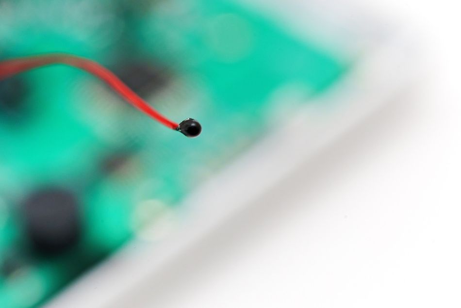
Once temperature rises, the thermistor’s resistance decreases, lowering the output voltage.
Choose the Thermistor: Choose a nominal resistance, beta value, and operating range suitable for the application. This example uses a 100 kΩ thermistor with B₂₅/₈₅ = 3977 K to measure temperatures from −25 °C to 100 °C.
Calculate the Resistance Limits: The beta equation gives approximately 1469.744 kΩ at −25 °C and 6.849 kΩ at 100 °C. These values define the resistance span that the divider must accommodate.
Size the Series Resistor: Set R1 to the geometric mean, √(6.849 kΩ × 1,469.744 kΩ) = 100.333 kΩ, and round to a standard 100 kΩ; this makes the voltage-versus-temperature relation more linear.
Use a Ratiometric Measurement: Power the divider from the same voltage used as the ADC reference. Ideally, variations in this shared voltage cancel during conversion, leaving the ADC result dependent on the resistance ratio. [3][8]
Check Resistor Tolerance and ADC Settling: Include the tolerance of a fixed resistor in the overall error budget; the example design uses 1%. Ensure that the source impedance of the divider allows the ADC input to settle within its acquisition time. A capacitor at the measurement node can help, but its value must suit the ADC and sampling rate. The reference design uses 100 pF for its 10 kHz implementation.
The result swings from 3.09 V at −25 °C to 210 mV at 100 °C on a 3.3 V supply, using 87% of the full-scale range in the ADC. [8]
Converting ADC Counts to Temperature
Ratiometric measurement reduces sensitivity to variations in the shared excitation and reference voltage, but it does not compensate for the nonlinear response in a thermistor. Accurate temperature measurement still requires a suitable conversion method.
Common approaches include a lookup table with interpolation, a polynomial fit, or the Steinhart–Hart equation. Lookup tables trade memory for computational simplicity, while equation-based methods require more arithmetic. On fixed-point microcontrollers, the logarithmic calculations used by Steinhart–Hart may require particular attention to execution time and numerical precision. [3]
Over a wide temperature range, conversion error can become a significant part of the measurement error budget. Use resistance tables or coefficients for the selected thermistor, and verify the conversion across the intended operating range. A narrower range generally makes approximation easier.
Keeping Self-Heating Effects Small
Current passing through the thermistor generates heat, raising its temperature above that of the surrounding medium. Keeping measurement power low helps minimise this error. In a constant-voltage divider, thermistor dissipation reaches its maximum when its resistance equals the fixed resistance. [1] In another design, that happens at 25 °C: 3.3 V across 200 kΩ drives 16.5 µA, so the thermistor dissipates about 27 µW. On a small glass element rated 1 mW/°C in still air, that would be a self-heating error of roughly 0.03 °C. [6]
NTC Thermistors as Inrush Current Limiters
Switch-mode power supplies, electric motors and transformers draw excessive inrush current at turn-on, which can damage components or trip fuses. [10]
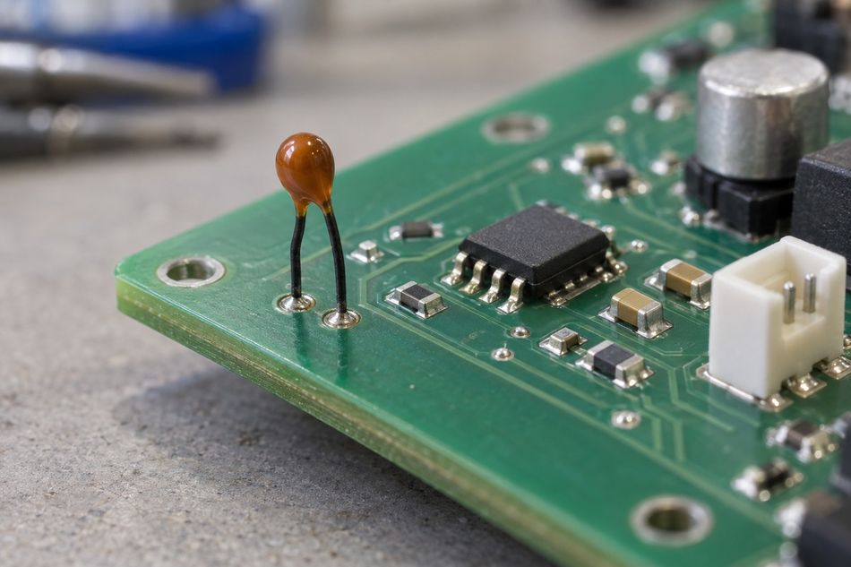
NTC thermistor resistor in series with the load limits the surge with its relatively high cold resistance. The current then heats it, and its resistance drops by a factor of 10 to 50.
How to Select an Inrush Current Limiter?
The selection method includes three inputs:
Check the Capacitive Load: In capacitor-input power supplies, charging the bulk capacitor is a major source of inrush current. Select a device whose maximum permissible capacitance covers the application capacitance, including tolerance, at the applicable supply voltage and specified test conditions. Capacitance rating should not be used independently of its associated voltage.
Check Continuous Current and Temperature Derating: The thermistor must carry the maximum steady-state current at the highest expected ambient temperature. Derating requirements vary between families: the S236 series maintains its full current rating from 0 °C to 65 °C, whereas several other families require derating above 25 °C. Allow additional margin for operating conditions such as line-voltage variation. [10]
Select the Initial Resistance: Among devices that satisfy the surge and continuous-current requirements, a higher R₂₅ generally provides greater inrush suppression. However, you must also consider resistance tolerance and the actual start-up temperature. A warm thermistor provides less protection than one starting at 25 °C.
Example: Consider a 230 V AC supply with 220 µF of bulk capacitance, drawing 2 A RMS in a 50 °C enclosure. Using the S236 series as an example:
Step 1: Every S236 part from 3 Ω up allows at least 300 µF at 230 V AC, which covers 220 µF.
Step 2: At 50 °C, the S236 needs no derating. The 25 Ω part is rated for 2.5 A, and the 40 Ω part for exactly 2.0 A, so 25 Ω is the highest resistance that leaves headroom.
Step 3: From a 25 °C start, the 25 Ω cold resistance limits the first peak to roughly 13 A (the mains peak of about 325 V divided by 25 Ω), before counting any other resistance in the circuit. Treat that as a best case: the part's tolerance is ±20 %, so a 20 Ω sample allows about 16 A, and in a 50 °C enclosure the thermistor starts warmer, so its cold resistance is lower still.
The resistance drops substantially during operation. For example, the 8 Ω device has a stated resistance of 0.152 Ω at 3.7 A. Its resulting dissipation is approximately 2.08 W, close to the stated 2.1 W maximum in series. Low hot resistance therefore does not eliminate the need to manage heat.
Three rules keep an NTC inrush current limiter healthy:
Series Only: Never connect ICLs in parallel: the part carrying the most current heats up until it takes the whole current, while the others stay cold.
Expect Heat: In extreme cases, the body reaches a mean temperature of up to 250 °C, and the contact areas can get quite hot at maximum load.
Plan Restarts: Full cold resistance returns only after 1 to 2 minutes, depending on the type, so bypass the thermistor after start-up when restarts must be fast.
NTC Thermistor Applications
Home Appliances and Automotive Applications: NTC thermistors monitor temperatures in refrigerators, air conditioners, vehicle intake systems, and transmission oil. Their feedback supports temperature regulation and thermal protection. Glass-encapsulated elements suit demanding thermal and humid environments, with automotive-qualified options available for vehicle applications. [6]
Battery Packs: NTC thermistors provide battery-temperature feedback so charging circuits can adjust or suspend charging outside permitted limits. For example, the BQ25176J uses a 10 kΩ thermistor to support normal charging from approximately 10 °C to 45 °C, reduced charging in adjacent temperature regions, and suspension below 0 °C or above 55 °C. The thermistor characteristic and charging profile must match the charger and battery requirements.
3D Printers: Many filament-based printers use 100 kΩ NTC thermistors to monitor the hot end and heated bed. Their readings allow the controller to regulate heater power and maintain printing temperatures. Correct firmware configuration and secure thermal contact are essential for dependable measurement.
Power Supplies and Inrush Protection: Power NTC thermistors limit the initial current surge when bulk capacitors charge at switch-on. Their relatively high initial resistance restricts the surge, then decreases as current heats the device, reducing its voltage drop during normal operation. [10]
Industrial Motors and Drives: NTC sensors monitor temperature in motors and associated drive equipment. Their feedback can support cooling control, load reduction, or shutdown when temperatures exceed configured limits. Sensor placement, electrical insulation, and thermal response must suit the monitored component.
Power Converters and Inverters: NTC thermistors provide temperature feedback in converters, inverters, and uninterruptible power supplies. Monitoring critical thermal locations helps control cooling and identify excessive heating. The measured temperature depends on the sensor’s proximity and thermal coupling to the heat source.
Heating and Cooking Appliances: NTC sensor assemblies are used in washing machines, dryers, coffee machines, and other heating appliances. Temperature feedback enables the controller to regulate heating through the operating cycle. Probe construction must match the environment, particularly where moisture, liquids, or elevated temperatures are present.
Recommended Reading: What is 3D Printer Thermal Runaway and How to Prevent It?
How to Test an NTC Thermistor With a Multimeter?
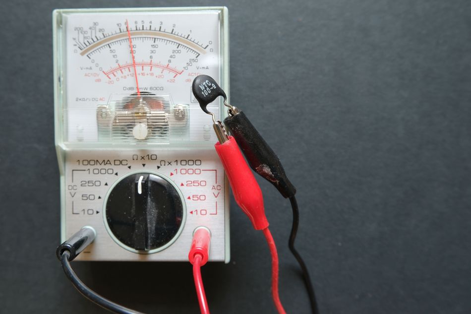
Follow the steps below:
Isolate It: Disconnect at least one lead, so other parts of the circuit do not load the reading.
Measure at Room Temperature: Compare the reading with the rated resistance: much lower suggests a short, much higher suggests an open circuit.
Allow for Tolerance and Temperature: Room temperature is rarely exactly 25 °C, and a ±5 % part can read more than 1 °C off even when healthy. [7] Use the R/T table in the datasheet at the actual temperature.
Check a Second Point: Ice water gives a convenient 0 °C, with the sensor wrapped to stay dry. [9] The TDK 10 kΩ part from the table above should read about 27.18 kΩ there, and the Vishay part about 32.55 kΩ. [6][7]
Confirm the Type: If the resistance falls as you warm the part, it is an NTC type; a PTC thermistor's resistance rises instead. [1][3]
In a live system, the same failures show up as out-of-range readings. Marlin 3D printer firmware reports an open thermistor as a MINTEMP error and, usually, shorted sensor wires as a MAXTEMP error, and shuts down in both cases. Slow ageing is harder to spot: it usually raises the resistance, which makes an NTC read low, so it takes a check against a known temperature to reveal it. [4]
Conclusion
NTC thermistor provides a compact, cost-effective solution for temperature sensing and inrush current limiting, but reliable performance depends on careful selection and integration. For temperature measurement, nominal resistance alone is insufficient: the beta value, resistance tolerance, thermal response, and conversion method all influence accuracy. Ratiometric measurement and controlled excitation help reduce supply-related errors and self-heating.
For inrush protection, selection must account for surge energy, continuous current, ambient temperature, and initial resistance, alongside cooling time between starts. Matching these electrical and thermal characteristics to the application allows engineers to achieve dependable operation while avoiding measurement errors, excessive heating, and inadequate protection during repeated power cycles.
Frequently Asked Questions
Q. What is the difference between NTC and PTC thermistors?
A. The resistance of an NTC thermistor falls as temperature rises, while the resistance of a PTC thermistor rises. Most NTC thermistors are ceramic, while PTC types are made from silicon, metal, ceramic, or polymer.
Q. How do you calculate the resistance of an NTC thermistor at a given temperature?
A. Use R(T) = R25 × exp[B × (1/T − 1/298.15 K)] with T in kelvin and the B value from the datasheet. For wide ranges, use the manufacturer's R/T table or Steinhart-Hart coefficients.
Q. What is the difference between NTC temperature sensors and RTDs?
A. NTC sensors are about ten times more sensitive than platinum resistance temperature detectors (RTDs) but far less linear, and measurement-grade types cover about −80 °C to 300 °C. Industrial platinum RTDs to IEC 60751 cover −200 °C to 850 °C.
Q. Is an NTC thermistor the same as a thermostat?
A. No. Thermostat is a device that detects temperature changes and switches a heating or cooling system to hold a space at an essentially constant temperature. NTC thermistor is a sensing component that a thermostat or controller can use to measure temperature.
References
[1] TDK. NTC Thermistors: General Technical Information [Cited 2026 October 20] Available at: Link
[2] IEC. IEC 60539-1:2022, Directly Heated Negative Temperature Coefficient Thermistors [Cited 2026 October 20] Available at: Link
[3] Texas Instruments. Methods to Reduce Thermistor Linearization Error, Memory, and Power Requirements Over Wide Operating Temperature Ranges [Cited 2026 October 20] Available at: Link
[4] MDPI. NTC Thermistors: General Technical Information [Cited 2026 October 20] Available at: Link
[5] TDK. Thermal Treatment of Aerosol Deposited NiMn2O4 NTC Thermistors for Improved Aging Stability [Cited 2026 October 20] Available at: Link
[6] BIPM. Guide on Secondary Thermometry: Thermistor Thermometry [Cited 2026 October 20] Available at: Link
[7] TDK. Temperature sensor (NTC), NTC elements, NTCD Series Catalog [Cited 2026 October 20] Available at: Link
[8] Texas Instruments. Monitoring NTC Thermistor Circuit With Single-Ended ADC (SBAA338A) [Cited 2026 October 20] Available at: Link
[9] Stanford Research Systems. Calibrate Steinhart-Hart Coefficients for Thermistors [Cited 2026 October 20] Available at: Link
[10] TDK. NTC Inrush Current Limiters: Application Notes [Cited 2026 October 20] Available at: Link
in this article
1. Key Takeaways2. Introduction3. What Is an NTC Thermistor?4. How an NTC Thermistor Works?5. Key NTC Thermistor Specifications6. Calculating NTC Thermistor Resistance and Temperature7. Designing an NTC Temperature Sensing Circuit8. NTC Thermistors as Inrush Current Limiters9. NTC Thermistor Applications10. How to Test an NTC Thermistor With a Multimeter?11. Conclusion12. Frequently Asked Questions13. References