Understanding Potentiometers: A Comprehensive Guide
An in-depth resource on potentiometer types, wiring, and applications.

21 Aug, 2025. 19 minutes read
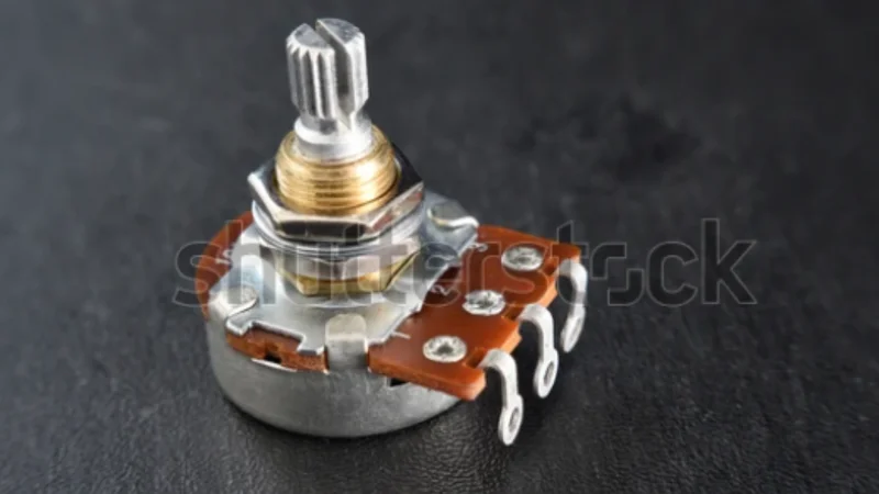
Rotary potentiometer, a common PCB component
<html><head></head><body><h2>Key Takeaways</h2><ul><li><p>Potentiometer Basics: A potentiometer (or “pot”) is a three-terminal variable resistor functioning as an adjustable voltage divider. Moving its wiper along a resistive element changes the output voltage and resistance, enabling precise control of electronic signals.</p></li><li><p>Types of Potentiometers: Potentiometers come in rotary (knob) and linear/slider formats, as well as small trimmers for calibration and digital potentiometers (digipots) for microcontroller control.</p></li><li><p>Wiring and Connections: Correct wiring is critical – typically one end to power, the other to ground, and the wiper as output. Understanding the 3-pin configuration (pin 1, 2, 3) and proper grounding ensures stable operation. </p></li><li><p>Applications and Integration: Potentiometers are used for volume control, dimmer switches, sensor adjustments, and more. Modern designs also use digital potentiometers interfaced via Arduino/Raspberry Pi (SPI/I²C) to adjust resistance in software for audio control or LED dimming applications.</p></li><li><p>Optimal Use and Troubleshooting: For best performance, choose appropriate resistance value, taper (linear vs log), and tolerance. Keep output impedance in mind – a pot’s output has max ~1/4 of its total resistance at mid-position. </p></li></ul><h2>Introduction</h2><p>In the world of electronics design, understanding potentiometers is essential for anyone working with adjustable controls or sensor calibration. Potentiometers are common components with applications ranging from the volume knob on an audio amplifier to the slider that dims your desk lamp. This comprehensive guide demystifies potentiometers by explaining what they are, how they work, and how to wire a potentiometer correctly for reliable operation. </p><p>We’ll explore the various types of potentiometers (rotary, linear/slide, trimmer, and digital), delve into the essential wiring of potentiometers (including diagrams and best practices for wiring a potentiometer into a circuit), and examine advanced integrations, such as digital potentiometers with microcontrollers. Short, focused sections with clear headings, step-by-step instructions, and illustrative diagrams will make these concepts accessible. </p><h2>What is a Potentiometer?</h2><h3>Definition and Basic Functionality</h3><p>A potentiometer (often abbreviated pot) is a three-terminal adjustable resistor that can provide a variable voltage output. In essence, it’s a resistor with a sliding or rotating contact (the wiper) that divides the resistor into two parts. By moving the wiper, you change the resistance between it and each end terminal, thereby adjusting the voltage or signal in a circuit. The main components of a potentiometer include:</p><ul><li><p>Resistive Element: A fixed resistor body (made of carbon composition, cermet, wirewound, or conductive plastic) forming a track or strip. This element has a certain total resistance (e.g. 1 kΩ, 10 kΩ, 100 kΩ, etc.).</p></li><li><p>Wiper: A movable contact that slides along the resistive element. The wiper effectively taps at some point between the two ends of the <a href="https://www.wevolver.com/article/resistor-chart-comprehensive-guide-to-resistor-values-e-series-and-color-codes" target="_blank">resistor</a>, splitting it into two resistances.</p></li><li><p>Terminals: Three terminals (pins). Two outer terminals (often called Terminal 1 and Terminal 3) connect to the ends of the resistive element, and the middle terminal (Terminal 2) connects to the wiper. </p></li></ul><p><span><span><span class="fr-img-caption fr-fic fr-dib"><span class="fr-img-wrap"><img src="https://images.wevolver.com/eyJidWNrZXQiOiJ3ZXZvbHZlci1wcm9qZWN0LWltYWdlcyIsImtleSI6ImZyb2FsYS8xNzU1NzczNjY0MDE3LWNpcmN1bGFyLXBvdGVudGlvbWV0ZXItcmVzaXN0YW5jZS1zY2FsZS5qcGciLCJlZGl0cyI6eyJyZXNpemUiOnsid2lkdGgiOjk1MCwiZml0IjoiY292ZXIifX19" class="fr-fic fr-dib" alt="Internal structure of a potentiometer: The wiper moves across the resistive arc for resistance change" /><span class="fr-inner">Fig 1: Internal structure of a potentiometer: The wiper moves across the resistive arc for resistance change</span></span></span><br /></span></span>In operation, a potentiometer can act as an adjustable voltage divider or a variable resistor depending on how it’s wired (more on that soon). Turn the knob or slide the lever, and the wiper moves along the resistive element. This physical motion translates to an electrical change: the resistance between the wiper and each end terminal increases or decreases inversely. </p><p><strong><em>Suggested Reading: <a href="https://www.wevolver.com/article/pcb-components-a-comprehensive-technical-guide-to-passive-active-and-electromechanical-parts" target="_blank">PCB Components: A Comprehensive Technical Guide to Passive, Active, and Electromechanical Parts</a></em></strong></p><h3>Voltage Divider Principle</h3><p>When used with all three terminals, a potentiometer serves as a voltage divider – a fundamental circuit configuration that outputs a fraction of an input voltage. In this configuration, the two end terminals are connected across a voltage source (for example, one end to a supply voltage VCC and the other to ground). The output is taken from the wiper. As the wiper moves, it divides the input voltage into two parts across the resistive element. The <a href="https://www.wevolver.com/article/what-causes-voltage-drop" target="_blank">output voltage</a> at the wiper is proportional to the ratio of the resistances on each side of the wiper.</p><p><span><span><span class="fr-img-caption fr-fic fr-dib"><span class="fr-img-wrap"><img src="https://images.wevolver.com/eyJidWNrZXQiOiJ3ZXZvbHZlci1wcm9qZWN0LWltYWdlcyIsImtleSI6ImZyb2FsYS8xNzUzNDI1NDU0OTc3LTE3NTM0MjU0NTQ5NzcucG5nIiwiZWRpdHMiOnsicmVzaXplIjp7IndpZHRoIjo5NTAsImZpdCI6ImNvdmVyIn19fQ==" class="fr-fic fr-dib" alt="Potentiometer as a voltage divider" /><span class="fr-inner">Fig 2: Potentiometer as a voltage divider</span></span></span><br /></span></span></p><p>For example, imagine a 1 kΩ potentiometer with 5 V applied across its end terminals. If the wiper is positioned exactly in the middle, it splits the 1 kΩ into two 500Ω halves. The wiper then sees an output of about 2.5 V, exactly half of the input. More generally, if the wiper is at 30% of the track (meaning one side is 30% of the total resistance and the other is 70%), the output will be ~30% of the input voltage. In fact, at extreme positions, the output approaches the supply voltage or ground. </p><h3>Common Applications</h3><p>Because they allow easy, continuous adjustment of voltage or signal levels, potentiometers show up in a myriad of applications:</p><ul><li><p>Volume Control: Potentiometers are classic audio volume knobs, acting as voltage dividers to attenuate signals, often with a logarithmic taper for smooth perception.</p></li><li><p>Lighting Dimmers: They are used in dimmer switches to adjust light brightness, either by directly varying resistance or controlling digital circuits.</p></li><li><p>Calibration and Sensors: Potentiometers serve as calibration adjustments in instruments and sensors, or as position sensors translating movement into proportional voltage.</p></li><li><p>Other Examples: Potentiometers are found in motor speed controllers, voltage regulators, and as user input knobs for various tunable settings in analog and hybrid systems.</p></li></ul><h2>Types of Potentiometers</h2><p>Not all potentiometers are created equal – they come in different designs optimized for various tasks. We can categorize potentiometers by their form factor, construction, and even by their adjustment curve (taper). </p><h3>Rotary Potentiometers</h3><p>These are the most common type, recognized as familiar round knobs you twist. A rotary pot features a circular resistive element, with a wiper connected to a rotating shaft that sweeps along this element to vary resistance.</p><h3>Linear Potentiometers</h3><p>Also known as slider potentiometers, these have a straight resistive element with a wiper that moves linearly back and forth. They typically feature a sliding handle for adjustment, offering intuitive visual feedback of the setting.</p><h3>Slide Potentiometers</h3><p>Slide potentiometers are a specific category of linear potentiometers optimized for user interface, featuring a lever or knob on a track for sliding adjustment. They are designed for smooth, frequent human interaction, especially in audio and lighting equipment.</p><h3>Trimmer Potentiometers (Trimpots)</h3><p>Trimmer potentiometers are small, often multi-turn, <a href="https://www.wevolver.com/article/smt-pcb-assembly-a-comprehensive-guide-to-surface-mount-technology-in-electronics" target="_blank">devices mounted directly on a PCB</a> for infrequent, precise adjustments. They usually require a screwdriver or small tool for "set-and-forget" calibration during circuit installation or service.</p><h3>Digital Potentiometers</h3><p>Digital potentiometers (digipots) are integrated circuits that electronically replicate a potentiometer's function, controlled by digital signals. They use internal resistor strings and solid-state switches to adjust resistance programmatically.</p><p>The following table summarizes the operations and applications of each pot type:</p><div id="isPasted"><table><tbody><tr><td><p>Pot Type</p></td><td><p>Operations</p></td><td><p>Applications</p></td></tr><tr><td><p>Rotary Pot</p></td><td><p>Features a circular arc inside and a wiper attached to the shaft. Turning the shaft causes the arc to move along the resistive material, causing resistance change.</p></td><td><ul><li><p>Audio volume control</p></li><li><p>Appliance control</p></li></ul></td></tr><tr><td><p>Linear Pot</p></td><td><p>Resistive element is laid out in a straight line and the slider moves along it, causing resistance change.</p></td><td><ul><li><p>Position sensing</p></li><li><p>Graphic equlizers</p></li></ul></td></tr><tr><td><p>Slide Pots</p></td><td><p>Similar to linear pots, but feature a knob or slider for distinct operations.</p></td><td><ul><li><p>Lighting dimmer panels</p></li><li><p>Studio mixers</p></li></ul></td></tr><tr><td><p>Trimpots</p></td><td><p>Feature a multiturn or single turn design, often mounted directly on a PCB. Used for infrequent settings in electrical circuits </p></td><td><ul><li><p>Calibration</p></li><li><p>Control systems</p></li></ul></td></tr><tr><td><p>Digital Pots</p></td><td><p>It’s an integrated chip featuring electronic switches that mimic an actual potentiometer. They come with serial communication interfaces for microcontrollers and development board integration. They are programmable and provide highly repeatable results.</p></td><td><ul><li><p>Remote automated adjustments</p></li><li><p>Multiplying DACs</p></li></ul></td></tr></tbody></table></div><h2>Potentiometer Wiring Essentials</h2><p>Wiring a potentiometer correctly is crucial to get the desired behavior. A potentiometer has three pins and can be wired in different configurations depending on whether you want a variable voltage output or a variable resistance. </p><p>A typical potentiometer will have the terminals arranged in a row or circle. Usually: </p><ul><li><p>Terminal 1 is one end of the resistive element</p></li><li><p>Terminal 2 is the wiper (middle pin)</p></li><li><p>Terminal 3 is the other end of the resistive element. </p></li></ul><h3>Voltage Divider Configuration</h3><p>In a voltage divider wiring (the most common), you connect Terminal 1 to your input voltage (VCC) and Terminal 3 to ground (0 V). The wiper (Terminal 2) will then provide an output voltage that ranges between 0 V and VCC as you turn the knob. </p><p>This is the configuration for using the pot as a variable voltage source (e.g., volume control knob providing a fraction of an audio signal, or a sensor providing an adjustable reference).</p><h3>Variable Resistor (Rheostat)</h3><p>If you want to use the potentiometer as a variable resistor (rheostat), you effectively use only two connections: one end and the wiper. For example, connect Terminal 1 and Terminal 2 (wiper) into the circuit and leave Terminal 3 unconnected (or tied to the wiper as well). Then, as you move the wiper, the resistance between the two used terminals varies from 0 Ω up to the full potentiometer value. </p><p><span><span><span class="fr-img-caption fr-fic fr-dib"><span class="fr-img-wrap"><img src="https://images.wevolver.com/eyJidWNrZXQiOiJ3ZXZvbHZlci1wcm9qZWN0LWltYWdlcyIsImtleSI6ImZyb2FsYS8xNzU1NzczNzE2MTM1LXdoZWF0c3RvbmUtYnJpZGdlLXJlc2lzdG9yLW5ldHdvcmsuanBnIiwiZWRpdHMiOnsicmVzaXplIjp7IndpZHRoIjo5NTAsImZpdCI6ImNvdmVyIn19fQ==" class="fr-fic fr-dib" alt="Example of rehostate in a wheatstone bridge (the wiper is short with on of the ends)" /><span class="fr-inner">Fig 3: Example of rehostate in a wheatstone bridge (the wiper is short with on of the ends)</span></span></span><br /></span></span></p><h3>Step-by-Step: How to Wire a Potentiometer (Breadboard/PCB Tutorial)</h3><p>Wiring a potentiometer into a circuit can be done in a few straightforward steps. Here we’ll outline a general procedure, whether you’re hooking it up on a breadboard for prototyping or soldering it onto a PCB or wires for a more permanent setup. </p><ol><li><p>Identify Terminals: Use a multimeter to find the fixed end terminals and the variable wiper (middle pin); note which end is which.</p></li><li><p>Disconnect Power: Always turn off circuit power before wiring to prevent damage.</p></li><li><p>Place Potentiometer: Mount the pot securely on a breadboard, PCB, or panel, ensuring correct pin orientation.</p></li><li><p>Wire Ground: Connect one end terminal (e.g., pin 3) to circuit ground (0V), typically with a black wire.</p></li><li><p>Wire Supply/Input: Connect the other end terminal (e.g., pin 1) to your supply voltage or signal input, typically with a red wire.</p></li><li><p>Wire Wiper (Output): Connect the middle wiper terminal (e.g., pin 2) to the component or input you wish to control.</p></li><li><p>(Optional Rheostat Safeguard): For two-terminal rheostat use, connect the unused end terminal to the wiper.</p></li><li><p>Double-Check Connections: Verify all connections, especially ground and supply, and confirm wiper voltage varies correctly with rotation.</p></li><li><p>Power Up and Test: Apply power and test the pot's smooth voltage variation and circuit function.</p></li></ol><p><strong><em>Further Reading: <a href="https://www.wevolver.com/article/how-to-wire-a-potentiometer" target="_blank">How to Wire a Potentiometer: A Comprehensive Guide for Engineers</a></em></strong></p><h3>Correct Soldering Techniques </h3><p>When permanently wiring a potentiometer (especially panel-mounted types or those that aren’t directly on a PCB), using proper soldering techniques is important to ensure a reliable connection and to avoid damaging the potentiometer. </p><ul><li><p>Use the Right Iron Temperature: Avoid excessive heat on the pot’s terminals. A good rule is to use a moderate iron temperature (around ard 350–370 °C or ~660–700 °F) and limit contact time to a few seconds per joint. For example, tests have shown that hand-soldering at 370 °C for no more than 5 seconds on a terminal gives a solid joint without damaging the pot. </p></li><li><p>Pre-tin and Quick Solder: It helps to pre-tin the wire and the pot’s lug. Apply a small amount of solder to the wire end and pot terminal separately, then join and heat briefly to fuse them. This way, you spend less time with the iron on the pot. Also use a clean iron tip with a bit of fresh solder for good thermal transfer. </p></li></ul><p><span><span><span class="fr-img-caption fr-fic fr-dib"><span class="fr-img-wrap"><img src="https://images.wevolver.com/eyJidWNrZXQiOiJ3ZXZvbHZlci1wcm9qZWN0LWltYWdlcyIsImtleSI6ImZyb2FsYS8xNzU1NzczNzQ5Mjk4LXNvbGRlcmluZy1jaXJjdWl0LWJvYXJkLXJlcGFpci5qcGciLCJlZGl0cyI6eyJyZXNpemUiOnsid2lkdGgiOjk1MCwiZml0IjoiY292ZXIifX19" class="fr-fic fr-dib" alt="A typical soldering setup for potentiometers" /><span class="fr-inner"><br />Fig 4: A typical soldering setup for potentiometers</span></span></span></span></span></p><ul><li>Support the Pot and Avoid Mechanical Strain: When soldering, pots can get hot and the terminals might move. Use a fixture or a third-hand tool to hold the pot steady. After soldering, ensure that moving the wires does not twist the pot’s terminals (this could crack the element inside). </li><li><p>Avoid Solder Bridges: The three lugs are often close together. Make sure solder doesn’t blob and short between terminals. If solder accidentally bridges between adjacent lugs, use <a href="https://www.wevolver.com/article/how-to-remove-solder-from-a-circuit-board" target="_blank">solder wick or a desolder pump</a> to remove it. </p></li><li><p>Soldering to Metal Casing: In some applications (like guitar electronics), people solder a ground wire to the metal casing of the pot to serve as a common ground. This requires heating the casing sufficiently to get the solder to flow on it. Be very careful here: the pot casing can act as a heatsink, and overheating it can damage the pot’s internal connections or even melt plastic inside. </p></li><li><p>Cleaning: After soldering, clean off flux residue (especially if it’s a rosin core solder) around the terminals. <a href="https://www.wevolver.com/article/a-practical-guide-to-solder-flux" target="_blank">Solder Flux</a> can cause corrosion over time. Use isopropyl alcohol and a brush. </p></li></ul><p><strong><em>Further Reading: <a href="https://www.wevolver.com/article/demystifying-soldering-techniques-a-comparison-of-wave-soldering-and-reflow-soldering" target="_blank">Demystifying Soldering Techniques: A Comparison of Wave Soldering and Reflow Soldering</a></em></strong></p><h3>Testing Soldered Potentiometers</h3><p>After wiring and soldering, using a multimeter is the best way to test that everything is connected correctly and the pot itself is functioning:</p><ul><li><p>Resistance Test: With the circuit power off, use a multimeter in resistance (Ω) mode. Measure between the two end terminals – you should see the fixed total resistance. Then measure between one end and the wiper. Rotate the pot slowly through its range and <a href="https://www.wevolver.com/article/circuit-board-testing-methods-what-you-need-to-know" target="_blank">verify</a> that the resistance reading changes smoothly from near 0 Ω up to the total value. Then measure between the wiper and the other end and do the same. </p></li><li><p>Continuity Test: If you suspect a pin isn’t connected (e.g., a cold solder joint or broken internal connection), use the multimeter’s continuity or low-ohm mode. Check that each soldered connection from the pot to the next point in the circuit is indeed connected. </p></li><li><p>Output Voltage Test: If the pot is wired as a voltage divider and the circuit can be powered safely, measure the output (wiper) voltage relative to ground while adjusting the pot. It should vary between 0 V and the supply smoothly. For instance, if using a 5 V supply, check that you can dial somewhere in between, say 2 V or 3 V, easily. If the output seems “stuck” at one voltage or jumps, recheck wiring and the pot’s operation.</p></li></ul><p><strong><em>Suggested Reading: <a href="https://www.wevolver.com/article/what-is-in-circuit-testing" target="_blank">What Is In-Circuit Testing? An Essential Guide for Engineers</a></em></strong></p><h2>Potentiometer Connections</h2><p>This section delves deeper into the specifics of the three-pin connections on a potentiometer and the best voltage and grounding practices.</p><h3>Understanding the 3 Pins </h3><p>A standard potentiometer has three pins, which we’ve labeled as pin 1, pin 2, and pin 3 (though remember, different datasheets might label them A, W, B or 1, 2, 3, etc.). The functionality of these pins is as follows:</p><ul><li><p>Pin 1 (End 1, often “CCW” end): This is one end of the resistive element. Frequently, this end is connected to the lower potential in the circuit (like ground) if we assume clockwise rotation makes the wiper move from pin 1 towards pin 3. </p></li><li><p>Pin 2 (Wiper, middle pin): This is the adjustable terminal. It has a variable resistance to pin 1 and pin 3. In a voltage divider use case, this is the output that gives a scaled voltage. Pin 2 will be electrically closer to pin 1 or pin 3, depending on the knob position. </p></li><li><p>Pin 3 (End 2, often “CW” end): This is the other end of the resistive element. Often connected to the higher potential (e.g., VCC). In many physical pots, pin 3 corresponds to the clockwise end – i.e., when you turn the knob fully clockwise, the wiper (pin 2) is touching pin 3, meaning the wiper is effectively at the same voltage as whatever pin 3 is connected to. </p></li></ul><p>Sometimes schematics explicitly label pot pins as CW (clockwise) and CCW (counter-clockwise), plus the wiper. This helps designers ensure the user experience matches expectations. </p><h3>Voltage and Grounding Best Practices</h3><p>Proper grounding and referencing are critical when connecting potentiometers to avoid noise and unexpected behavior:</p><ul><li><p>Always ground one end: It might sound obvious now, but it’s worth reiterating – if you want a stable reference, one end of the pot should typically be at ground (or a defined reference voltage). A floating end will make the output unpredictable. </p></li><li><p>Decouple High Impedance Nodes: The wiper node can be a <a href="https://www.wevolver.com/article/controlled-impedance" target="_blank">high impedance source</a> (especially mid position as discussed, output ~R/4). If this is feeding an analog-to-digital converter (ADC) or a sensitive input, consider adding a small capacitor from wiper to ground to stabilize the voltage. </p></li><li><p>Star Grounding: If the potentiometer is part of an analog signal path, ensure that the ground it’s tied to is low-noise. Ground loops or sharing ground with a noisy digital return path can inject hum or interference into the pot’s output. </p></li><li><p>Orientation for Safety: Sometimes you have a choice which end of the pot goes to ground vs. supply. If the pot is being used to limit current or as a rheostat in something like a dimmer, a good practice is to have the wiper go to the load and one end to ground, the other end to supply. If the wiper loses contact, tying it to ground through the other end or making sure the default is safe is important. </p></li><li><p>Use a Grounded Case (if metal): Many panel potentiometers have a metal bushing and shaft. Often, the metal case is internally connected to the counter-clockwise end . In audio, the metal case is usually grounded to act as a shield. If you mount the pot on a metal panel that is grounded, its case is automatically grounded. If not, you might consider connecting the case to ground (there may be a tab or you can use a toothed washer). </p></li></ul><p><strong><em>Suggested Reading: <a href="https://www.wevolver.com/article/what-is-gnd-in-a-circuit-the-complete-guide-for-digital-design-and-hardware-engineers" target="_blank">What is GND in a Circuit: The Complete Guide for Digital Design and Hardware Engineers</a></em></strong></p><h2>Advanced Applications</h2><p>Potentiometers aren’t just simple volume knobs; they also find roles in more advanced and modern electronics scenarios. This section will focus on some advanced uses and integrations.</p><h3>Digital Potentiometers in Modern Electronics</h3><p>A typical digital potentiometer comes in an IC package and might have specifications like “256 steps, 100 kΩ total, +5 V max, <a href="https://www.wevolver.com/article/i3c-vs-i2c" target="_blank">I²C interface</a>”. These are widely used in modern consumer and industrial electronics. Here are some use case examples of digital potentiometers:</p><div id="isPasted"><table><tbody><tr><td><p>Use Case</p></td><td><p>Description</p></td></tr><tr><td><p>Calibration and Tuning</p></td><td><ul><li><p>Enable automatic or software-based calibration, replacing manual adjustments. </p></li><li><p>Allow remote tuning of instruments and industrial controls, eliminating the need for on-site technician intervention.</p></li></ul></td></tr><tr><td><p>Programmable Gain Amplifiers</p></td><td><ul><li><p>Serve as variable resistors in op-amp circuits, creating programmable gain amplifiers. </p></li><li><p>Allows systems to adapt to changing conditions or perform self-tests by adjusting gain ranges dynamically.</p></li></ul></td></tr><tr><td><p>Digital Audio Control</p></td><td><ul><li><p>Provide digital control for audio volume and tone in mixers and amplifiers. </p></li><li><p>Offer click-less, precise, and channel-matched adjustments, ideal for remote-controlled stereo volume.</p></li></ul></td></tr><tr><td><p>Communication Systems</p></td><td><ul><li><p>Enable software-controlled tuning of filters or bias points in RF circuits.</p></li><li><p>Microcontrollers can adjust them to compensate for frequency drift or component aging, ensuring system stability.</p></li></ul></td></tr></tbody></table></div><h3>The Downside of Digipots</h3><p>Despite their benefits, digital potentiometers have some limitations, such as:</p><ul><li><p>Digipots typically handle lower voltages (e.g., 0-5V) and currents (milliamps), often limited by digital supply rails.</p></li><li><p>They offer discrete steps (e.g., 256 for 8-bit), which can be coarser than analog resolution, though often sufficient.</p></li><li><p>Digipots can introduce minor noise when changing resistance steps and may have temperature-dependent resistance.</p></li><li><p>Replacing a mechanical pot is simple: connect high to high reference, low to low reference, and wiper to the circuit.</p></li><li><p>The digital pins connect to a microcontroller, and it requires its own power and ground connections</p></li></ul><h2>Integration with Arduino, Raspberry Pi, STM32 (Microcontroller Examples)</h2><p>Microcontrollers and single-board computers have made it easy to integrate potentiometers both in the analog sense and via digital potentiometers. Let’s break it into two parts: </p><ul><li><p>Using a mechanical potentiometer as input to a microcontroller </p></li><li><p>Using a microcontroller to control a digital potentiometer</p></li></ul><h3>Using a Potentiometer with Microcontrollers (Analog Input)</h3><p>One of the simplest inputs to, say, an Arduino is a potentiometer. You wire a pot as a 3-wire voltage divider (5 V–wiper–GND) and connect the wiper to an analog input pin. In Arduino code, an analogRead() will give you a value corresponding to the knob position. This can then be used to control something else in code (e.g., the brightness of an LED via PWM, the angle of a servo, etc.). </p><p><span><span><span class="fr-img-caption fr-fic fr-dib"><span class="fr-img-wrap"><img src="https://images.wevolver.com/eyJidWNrZXQiOiJ3ZXZvbHZlci1wcm9qZWN0LWltYWdlcyIsImtleSI6ImZyb2FsYS8xNzU1NzczNzg0NDMzLXJlZC1lbGVjdHJvbmljcy1jb250cm9sLWJvYXJkLXdpdGgta25vYnMuanBnIiwiZWRpdHMiOnsicmVzaXplIjp7IndpZHRoIjo5NTAsImZpdCI6ImNvdmVyIn19fQ==" class="fr-fic fr-dib" alt="Smart shield with potentiometer interfaced with a microcontroller" /><span class="fr-inner">Fig 5: Smart shield with potentiometer interfaced with a microcontroller</span></span></span><br /></span></span></p><p>This is a fundamental lesson in many Arduino starter guides. Similarly, on an STM32 or other MCU with ADC, you’d do the same – read the analog value from the pot to get user input. </p><h3>Controlling a Digital Potentiometer with a Microcontroller</h3><p>This flips it around: instead of the pot feeding the microcontroller, the microcontroller sets the pot value. As described, digital pots typically use serial communication. For instance, using Arduino again, libraries or simple SPI routines can be used to send commands to a digital pot chip. Let’s say we have a Microchip MCP41100 (100 kΩ single digital pot, SPI). </p><p>We connect MCP41100’s P0A pin to 5 V, P0B to ground, and P0W (wiper) to some circuit (like an LED’s series resistor node or an op-amp input). Then from Arduino, we connect MOSI, SCK, and a Chip Select pin to the MCP41100’s CS, SDI, and CLK pins, and also power the MCP41100 at 5 V and ground. </p><h3>Raspberry Pi integration </h3><p>It often goes via I²C or SPI as well, since Raspberry Pi is a 3.3 V logic computer with those buses. One might use a digital pot in a Raspberry Pi hat to control analog audio output volume, for example, commanded by the Pi.</p><p>One more neat integration: some microcontrollers (or companion chips) have built-in digital potentiometer functionality. For example, certain DSP or codec chips have integrated volume controls or filters that mimic digipot behavior. But if not, an external digipot is the straightforward way.</p><p><strong><em>Suggested Reading: <a href="https://www.wevolver.com/article/i2c-vs-spi-protocols-differences-pros-cons-use-cases" target="_blank">I2C vs SPI: A Comprehensive Comparison and Analysis</a></em></strong></p><h2>Tips for Optimal Performance</h2><p>Getting the most out of a potentiometer in your design involves more than just wiring it correctly. You must consider the component’s characteristics (impedance, tolerance, etc.), how it interacts with the rest of your circuit, and your reliability plan. In this section, we’ll provide tips on ensuring optimal performance, covering impedance and accuracy considerations as well as troubleshooting common issues that can arise with potentiometer use.</p><h3>Impedance and Resistance Accuracy Considerations</h3><p>The following table summarizes the resistance and accuracy considerations for potentiometers:</p><div id="isPasted"><table><tbody><tr><td><p>Aspect</p></td><td><p>Issue/Consideration</p></td><td><p>Details/Implications</p></td><td><p>Recommendations/Solutions</p></td></tr><tr><td><p>Impedance Matching</p></td><td><p>Pot output impedance can be significant</p></td><td><p>At mid-point, output impedance ≈ R/4 (e.g., 100 kΩ pot → 25 kΩ impedance)</p></td><td><p>Use load impedance ≥10× pot impedance or buffer with op-amp</p></td></tr><tr><td><p>ADC Compatibility</p></td><td><p>High impedance affects ADC accuracy</p></td><td><p>Microcontroller ADCs (like Arduino) may misread signals if source impedance >10 kΩ</p></td><td><p>Use 10 kΩ pots or add op-amp buffer</p></td></tr><tr><td><p>Driving Loads</p></td><td><p>Pot may be connected to multiple inputs or cables</p></td><td><p>Creates loading or tone distortion (especially in audio systems)</p></td><td><p>Use op-amp voltage follower to isolate pot output</p></td></tr><tr><td><p>Resistance Tolerance</p></td><td><p>Pots have manufacturing tolerance</p></td><td><p>Carbon pots ±20%, better pots ±10%, ±5%, ±1% → mismatched channels possible</p></td><td><p>Use precision/matched pots, or calibrate</p></td></tr><tr><td><p>Linearity</p></td><td><p>Linear pots may not be perfectly linear</p></td><td><p>Cheap pots may deviate 5%+ from ideal resistance vs. rotation behavior</p></td><td><p>Use better quality pots, digital pots, or software calibration</p></td></tr><tr><td><p>Temperature Coefficient</p></td><td><p>Resistance changes with temperature</p></td><td><p>Carbon has high tempco (hundreds of ppm/°C); may drift in warm environments</p></td><td><p>Use wirewound or cermet pots for stability</p></td></tr><tr><td><p>Noise</p></td><td><p>Wiper contact can cause fluctuating signals</p></td><td><p>Especially problematic in audio or analog circuits (“scratchy” sound or signal dropouts)</p></td><td><p>Use conductive plastic pots; prefer sealed models to avoid dust</p></td></tr><tr><td><p>Power Handling</p></td><td><p>Exceeding power rating damages pot</p></td><td><p>Small pots handle 0.1–0.5 W; overuse causes overheating and lifespan reduction</p></td><td><p>Derate power (use pot with 2× expected dissipation); avoid power use unless specified</p></td></tr><tr><td><p>End-Point Stress</p></td><td><p>Running full current at one end of pot</p></td><td><p>Resistive track has non-zero "end resistance"; full current can burn the pot or affect calibration</p></td><td><p>Add fixed resistor in series to limit current; avoid using pot as near-short without protection</p></td></tr><tr><td><p>Build Quality & Brand</p></td><td><p>Poor quality pots degrade quickly</p></td><td><p>Generic pots may fail early, produce noise, or lose contact</p></td><td><p>Use reputable brands (e.g., Bourns, Vishay); check datasheets for life cycle, torque, electrical limits</p></td></tr></tbody></table></div><h3>Troubleshooting Common Wiring and Performance Issues</h3><p>Even with the best practices, things can go wrong. Here are common issues that arise with potentiometers and how to address them:</p><div><table><tbody><tr><td><p>Symptom</p></td><td><p>Possible Causes</p></td><td><p>Diagnosis Tips</p></td><td><p>Recommended Fix</p></td></tr><tr><td><p>Erratic or Jumping Output</p></td><td><p>- Loose wiring or bad solder joint- Dirt/dust/oxidation on wiper- Worn-out pot</p></td><td><p>- Flickering or jumpy readings- Resistance changes abruptly while rotating</p></td><td><p>- Reflow solder joints- Rapidly rotate knob back/forth 10–20 times- Use contact cleaner- Replace pot if needed</p></td></tr><tr><td><p>No Output / Only Full or Zero Output</p></td><td><p>- Broken/miswired pin- Wiper shorted/open- Incorrect wiring</p></td><td><p>- Output stuck high/low regardless of knob- Use continuity mode to verify wiring</p></td><td><p>- Check all 3 pins are correctly connected- Ensure no solder shorts- Rewire/fix connections as needed</p></td></tr><tr><td><p>Output Stuck at Half (or Fixed Value)</p></td><td><p>- Wiper disconnected- Missing ground connection</p></td><td><p>- Output stays around mid-supply- Input (like ADC) reads mid-value even when knob turns</p></td><td><p>- Check and fix wiper and ground wiring- Ensure all three terminals are properly connected</p></td></tr><tr><td><p>Crackling / Scratchy Noise (Audio)</p></td><td><p>- Dirty/worn tracks- Grounding/shielding issues- DC current through pot</p></td><td><p>- Crackles during or after turning- Worse with vibration or EMI- Multimeter shows no resistance smoothness</p></td><td><p>- Clean pot- Replace worn pot- Add shielding/grounding- Redesign to avoid DC across pot (use AC coupling)</p></td></tr><tr><td><p>Stereo Channel Mismatch</p></td><td><p>- Pot resistance/taper mismatch- Poor tracking in dual-gang pots</p></td><td><p>- One audio channel louder than other- Volume imbalance at same knob position</p></td><td><p>- Use precision/matched pots- Add trim pot or software balance adjustment</p></td></tr><tr><td><p>Mechanical Issues</p></td><td><p>- Loose or stiff shaft- Worn internal components- Damaged stops or wrong component (e.g., encoder used instead of pot)</p></td><td><p>- Hard/loose turn- Knob rotates endlessly- No change in signal when turning</p></td><td><p>- Replace worn pots- Verify part type (pot vs. encoder)- Use component with correct mechanical specs</p></td></tr></tbody></table></div><h2>Conclusion</h2><p>Potentiometers are simple yet versatile components, widely used in electronics for adjustable voltage control. They function as variable voltage dividers and come in many forms, including rotary, slider, trimmer, and digital types. This guide covered their fundamental operation, correct wiring methods, and practical applications such as audio volume control, light dimming, and sensor calibration. We also explored how they integrate with microcontrollers, and shared tips on selecting the right impedance and tolerance, along with troubleshooting advice for common issues like erratic output or noise.</p><p>As electronics evolve, potentiometers remain essential. While digital versions and microcontroller-controlled digipots offer new capabilities like remote adjustment and automated calibration, traditional pots still play a key role in prototyping and product design—offering tactile control that buttons can’t replicate. Understanding both their theory and real-world usage equips you to confidently include them in your circuits. With good wiring practices, attention to specifications, and thoughtful integration, potentiometers can enhance both functionality and user experience in analog and hybrid systems.</p><h2>FAQs</h2><ol><li><h3><em>What is the difference between a potentiometer and a rheostat?</em></h3></li></ol><p><em>A potentiometer is a three-terminal device used as an adjustable voltage divider, whereas a rheostat is a two-terminal variable resistor used to control current. In practice, they can be the same physical component wired differently. When you use all three terminals (two ends and wiper) to tap a fraction of a voltage, it’s a potentiometer. If you use just two terminals (wiper and one end) to vary resistance in series with a load, it’s acting as a rheostat. Rheostats are often larger and designed to handle higher power (e.g., for lamp dimming or motor speed control in old designs), while potentiometers are typically for low-power signal adjustments.</em></p><ol><li><h3><em>How do I wire a 3-terminal potentiometer correctly?</em></h3></li></ol><p><em>Connect one outer terminal of the potentiometer to your voltage source (e.g., VCC) and the other outer terminal to ground. Then connect the middle terminal (wiper) to the input of whatever you’re controlling (or output measurement point). This forms a voltage divider. If wired this way, the wiper will output a variable voltage between 0 V and VCC as you turn the knob. If you find the control is “reversed” (e.g., clockwise rotation lowers the value), simply swap the two outer wires. Always ensure the ground side of the pot is actually connected to the circuit ground; a common mistake is leaving one end floating, which will prevent the pot from working properly.</em></p><ol><li><h3><em>What does “linear taper” vs “logarithmic taper” mean for potentiometers?</em></h3></li></ol><p><em>“Taper” describes how the resistance changes relative to the movement of the wiper. A linear taper potentiometer changes resistance in direct proportion to the knob position – 50% rotation gives ~50% of the resistance (and output voltage). A logarithmic taper (also called audio taper) changes resistance exponentially with rotation, which is useful for volume controls because the human ear perceives loudness on a logarithmic scale. With a log taper pot, at 50% rotation the resistance might be around 10% or 90% (depending on design) such that the output in a volume circuit corresponds to about half perceived volume. Log taper pots are typically marked with an “A” (in some regions) or specifically noted as audio taper, whereas linear are marked “B” (in some conventions). </em></p><ol><li><h3><em>How can I tell if my potentiometer is bad or needs replacement?</em></h3></li></ol><p><em>Signs of a bad potentiometer include: dead spots (no change in output over part of the rotation), scratchy or crackling noise that cleaning doesn’t fix, erratic jumping of values despite secure wiring, or inability to reach 0 or max values even at the ends. To test, use a multimeter: measure the resistance between the wiper and each end while turning the shaft slowly. The resistance should change smoothly (either increase on one side while decreasing on the other). If you observe sudden opens (infinite resistance) or large jumps not corresponding to movement, the track or wiper might be damaged. </em></p><ol><li><h3><em>What are digital potentiometers and when should I use one?</em></h3></li></ol><p><em>A digital potentiometer is an electronic component that replicates a potentiometer’s function (variable resistor/voltage divider) using a digital interface (controlled by I²C, SPI, or up/down pulses). Use a digital pot when you need to adjust resistance electronically rather than by a user’s hand. For example, if you want to allow a microcontroller or computer to adjust a volume level, calibration setting, or bias in a circuit, a digital pot is ideal. They are commonly used in applications requiring frequent or remote adjustments – automated test equipment, digitally controlled audio mixers, programmable gain amplifiers, etc. They eliminate mechanical wear and can be more precise/repeatable in setting values. However, they have limitations (voltage, current, resolution) so they’re generally for signal-level or control uses, not high power. If your design already has a microcontroller and you find yourself thinking “I wish I could turn that analog knob automatically,” a digital potentiometer is likely the solution.</em></p><ol><li><h3><em>Can I use a potentiometer to directly control a large LED or motor?</em></h3></li></ol><p><em>Not directly in most cases. While a potentiometer can vary resistance, standard pots are low-power devices (often rated <1 W). For an LED: If it’s a single low-current LED, you could use a pot in series to limit current and thus dim it. But for power LEDs (high-brightness LEDs with hundreds of mA) or LED strips, a pot would overheat or not handle the current. It’s better to use the pot to control a driver (e.g., a PWM dimmer or a transistor circuit) which then adjusts the LED brightness. For a motor: A small toy motor might be dimmed with a pot as a rheostat, but anything that draws substantial current will either burn the pot or result in poor control (also inefficient, as the pot will dissipate heat). </em></p><h2>References</h2><ol><li><p>"Potentiometer as a Voltage Divider - GeeksforGeeks." [Online]. Available: <a href="https://www.geeksforgeeks.org/physics/potentiometer-as-a-voltage-divider/" target="_blank">https://www.geeksforgeeks.org/physics/potentiometer-as-a-voltage-divider/</a></p></li><li><p>"Potentiometer Voltage Divider," All About Circuits. [Online]. Available: <a href="https://www.allaboutcircuits.com/textbook/experiments/chpt-3/potentiometer-voltage-divider/" target="_blank">https://www.allaboutcircuits.com/textbook/experiments/chpt-3/potentiometer-voltage-divider/</a></p></li><li><p>"The Potentiometer: Pinout, Wiring, and How It Works," Build Electronic Circuits. [Online]. Available: <a href="https://www.build-electronic-circuits.com/potentiometer/" target="_blank">https://www.build-electronic-circuits.com/potentiometer/</a></p></li><li><p>"Different Types Of Potentiometers And How To Use Them In Your Designs," Components101. [Online]. Available: <a href="https://components101.com/articles/different-types-of-potentiometers-and-how-to-use-them" target="_blank">https://components101.com/articles/different-types-of-potentiometers-and-how-to-use-them</a></p></li><li><p>"Potentiometers – The Complete Guide | DigiKey," Digi-Key Electronics. [Online]. Available: <a href="https://www.digikey.com/en/articles/the-complete-guide-to-potentiometers?msockid=08eb888217e1655e0bb5999916646492" target="_blank">https://www.digikey.com/en/articles/the-complete-guide-to-potentiometers?msockid=08eb888217e1655e0bb5999916646492</a></p></li><li><p>"Potentiometer: Working Principle and Basics." [Online]. Available: <a href="https://www.electronics-tutorials.ws/resistor/potentiometer.html" target="_blank">https://www.electronics-tutorials.ws/resistor/potentiometer.html</a></p></li><li><p>"How to Wire a Potentiometer: 10 Steps." [Online]. Available: <a href="https://www.wikihow.com/Wire-a-Potentiometer" target="_blank">https://www.wikihow.com/Wire-a-Potentiometer</a></p></li></ol></body></html>