Terminal Block Selection: Types, Ratings, and Wiring
A terminal block provides a secure electrical and mechanical connection between conductors. This guide explains how to select terminal blocks based on connection technology, current and voltage ratings, conductor size, mounting method, environmental conditions, and potential failure modes.

18 Sep, 2026. 25 minutes read
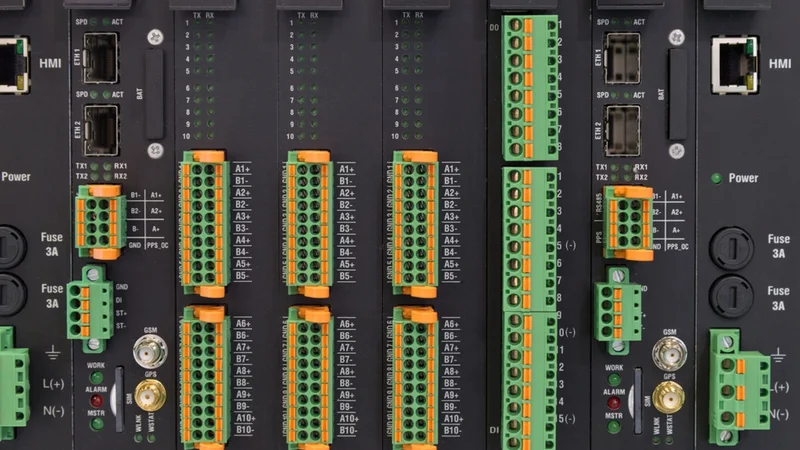
Terminal blocks provide organized connection points for wiring in industrial electrical and control systems.
Key Takeaways
Connection technology determines installation and service behavior. Screw clamp, spring clamp, push-in, and insulation displacement connections differ in conductor preparation, vibration performance, installation time, and whether controlled tightening is required. Select the connection method before comparing part numbers.
Ratings depend on the applicable standard. IEC 60947-7-1 and UL 1059 use different test and rating frameworks for terminal blocks. A single component may therefore carry different IEC and UL current or voltage ratings; the applicable rating must match the installation standard and conditions.
Terminal block types are application-specific. Feed-through, ground, fused, disconnect, multi-level, barrier, pluggable, and PCB-mounted designs address different requirements for circuit routing, protection, isolation, space, and serviceability.
Termination quality affects thermal performance. An inadequate or loose connection can increase contact resistance and generate localized heating. Over time, thermal cycling can accelerate conductor, insulation, and terminal degradation, making correct conductor preparation, tightening, and inspection essential.
Terminal blocks and power distribution blocks serve different functions. A terminal block primarily provides conductor termination and circuit interconnection, while a power distribution block is designed to distribute power among multiple conductors. Their construction, ratings, and applicable certification requirements are not interchangeable.
Introduction
A terminal block is a small component with a disproportionately important role in an electrical system. It sits at the point where conductors are terminated, circuits are interconnected, and electrical continuity must be maintained over the life of the installation.
That makes terminal block selection a question of connection integrity rather than simply connector compatibility. The design of the clamping mechanism, conductor interface, insulation body, and mounting system determines how the connection behaves during installation and under electrical, mechanical, and environmental stress.
The engineering challenge is to match the terminal block to the circuit, conductor, installation method, and operating conditions without adding unnecessary complexity or compromising serviceability.
What a Terminal Block Is and Why the Choice Matters
IEC 60947-7-1:2025 defines terminal blocks as devices with screw-type or screwless-type clamping units, primarily intended for industrial or similar applications, that are fixed to a support and provide an electrical and mechanical connection between copper conductors. The support may be a DIN rail, mounting plate, or printed circuit board (PCB), depending on the terminal block design.
The definition highlights two functions that are easy to overlook. A terminal block must establish a low-resistance electrical path while mechanically securing the conductor against movement, pullout, and other installation stresses. The clamping system therefore becomes a critical part of the connection rather than simply a means of holding the wire in place.
The current IEC 60947-7-1:2025 standard covers round copper conductors from 0.05 mm² (30 AWG) to 300 mm² (600 kcmil) for circuits rated up to 1,000 V AC at frequencies up to 1,000 Hz or 1,500 V DC. The unusually broad range illustrates why terminal blocks cannot be selected by appearance or conductor size alone. A small PCB terminal handling sensor signals and a high-current DIN rail terminal serving a feeder circuit may both be called terminal blocks while having fundamentally different electrical, mechanical, and thermal requirements.
In North America, UL 1059, Standard for Terminal Blocks, provides another important evaluation framework. Its sixth edition, published December 11, 2024, covers terminal blocks rated at 1,500 V or less and also addresses protective conductor terminal blocks. UL 1059 explicitly distinguishes terminal blocks from field-installed power distribution blocks, which are evaluated under a separate standard.
The choice therefore affects more than whether a wire can be connected. The terminal's conductor range, clamping technology, current and voltage ratings, insulation system, mounting method, environmental requirements, and certification all determine whether the connection is suitable for the application.
A connection can also degrade after installation. Insufficient clamping force, improper conductor preparation, damaged strands, or incorrect tightening can increase contact resistance. The resulting localized heating can accelerate thermal degradation and further compromise the connection. For this reason, wire termination is part of the electrical design, not merely an assembly task.
For engineers designing a control panel, the terminal block is therefore part of the circuit's interface between conductors, equipment, and maintenance personnel. Its selection influences electrical performance, wiring density, serviceability, and the long-term reliability of the installation.
Connection Technology: The First Decision
The connection mechanism determines how a conductor is retained, how contact force is generated, and how the joint responds to vibration, thermal cycling, installation error, and repeated servicing. It should therefore be selected before comparing individual terminal blocks.
Four connection technologies dominate industrial wiring: screw clamp, spring clamp, push-in, and insulation displacement. Bolt connections extend the same principle of mechanically generated contact force into higher-current applications, while quick-connect arrangements prioritize rapid mating and demating.
Screw Clamp
A screw clamp uses a threaded fastener to apply mechanical force to the conductor, typically through a clamp plate, cage, or other current-carrying element. The electrical objective is to maintain sufficient normal force at the conductor-contact interface to keep contact resistance low.
The main engineering variable is installation torque. Too little torque can reduce contact pressure and increase resistance; excessive torque can damage the conductor, terminal, or clamping mechanism. For this reason, a screw terminal should be installed according to the manufacturer's specified torque rather than tightened by feel.
Screw connections remain widely used because they accommodate a broad range of conductor sizes and can provide high clamping forces. Some designs incorporate mechanical locking features that compensate for the effects of vibration and thermal cycling. These features reduce the tendency for the threaded assembly to lose preload during service.
Spring Clamp
A spring clamp uses a preloaded spring element to maintain contact pressure on the conductor. Unlike a screw connection, the contact force is generated by the terminal rather than being established primarily by installer-applied torque.
This distinction matters in applications exposed to vibration or repeated temperature changes. As the conductor and terminal expand and contract at different rates, the spring can accommodate small changes in position while maintaining contact pressure. It also reduces the dependence of connection quality on individual installer technique.
Spring-cage designs generally require a tool to open the clamping point, after which the spring retains the conductor. Their suitability depends on the terminal's specified conductor range, conductor type, ferrule compatibility, and environmental requirements.
Push-In
A push-in terminal block uses a spring contact that allows a suitable conductor to be inserted directly into the clamping point. Rigid conductors and properly prepared stranded conductors can often be inserted without a screwdriver, while some designs use a release tool or pusher for removal and for inserting smaller conductors.
The primary advantage is assembly speed. Eliminating the tightening step reduces the number of operations required for each electrical connection, which becomes significant in high-volume control panel wiring. The spring also establishes the contact force independently of manual tightening.
Push-in does not mean that every conductor can simply be inserted without preparation. The terminal manufacturer's specifications determine acceptable conductor types, cross-sectional area, ferrule requirements, insertion method, and removal procedure. A ferrule, where specified for stranded conductors, can also improve conductor handling by consolidating the strands before insertion.
Insulation Displacement (IDC)
An insulation displacement connector (IDC) establishes contact by penetrating the conductor insulation with a shaped contact element. The conductor does not require conventional stripping before termination, reducing the number of preparation steps.
IDC is most useful where large numbers of relatively small conductors must be terminated quickly and consistently. Its application is therefore more common in control and signal wiring than in high-current circuits. The allowable conductor construction, insulation diameter, cross-sectional area, and contact geometry must match the manufacturer's specification.
IDC should not be confused with conventional screw terminal blocks or spring connections. The contact is established through a controlled displacement of insulation, making conductor compatibility a critical selection parameter.
Bolt Connection and Quick Connect
Bolt connections extend mechanically fastened termination into higher-current applications. They typically accept ring or fork cable lugs and use a threaded fastener to generate the required contact force. The large contact interface and high mechanical retention make this approach suitable for conductors that are too large for conventional clamp-style terminals.
Quick-connect arrangements take the opposite approach. A male blade or tab mates with a corresponding female connector, allowing rapid assembly and removal without a screw or spring-clamp operation. They are useful where service speed is important, but the electrical and mechanical ratings of the mating pair must be considered together.
Recommended reading: Enhancing Assembly Efficiency with Aratas's XW4M/XW4N Push-In Terminal Block PCB Connectors
Comparing Connection Technologies
Connection technology | How contact force is generated | Main installation consideration | Typical advantage | Key limitation |
Screw clamp | Installer-applied screw torque | Correct torque and conductor preparation | High clamping force and broad conductor compatibility | Installation quality depends on correct tightening. |
Spring clamp | Preloaded spring | Correct conductor insertion and preparation | Consistent contact force and good tolerance of movement | Conductor range and preparation requirements vary. |
Push-in | Spring activated by conductor insertion | Correct conductor type and insertion depth | Fast, repeatable wiring | Not all conductors can be inserted directly. |
IDC | Contact penetrates insulation. | Correct conductor size and insulation geometry | No conventional stripping step | More limited conductor and application range |
Bolt connection | Bolt torque acting through a lug | Lug selection and controlled tightening | High-current termination | Larger footprint and slower assembly |
Quick connect | Mating force between blade and receptacle | Correct mating geometry and retention | Rapid connection and disconnection | Requires compatible mating hardware |
The important distinction is not which technology is inherently superior. Each establishes and maintains contact force differently. The selection should therefore follow the circuit's current, conductor construction, vibration exposure, temperature range, assembly process, maintenance requirements, and available termination tools.
Recommended reading: Understanding the Connector Landscape: Types and Design Trade-offs
Terminal Block Types: The Functional Taxonomy
Connection technology and terminal block function are two different selection criteria. A screw clamp, spring clamp, or push-in mechanism describes how the conductor is secured. The terminal's function describes what the connection does in the circuit. The same function can therefore be implemented with different connection technologies.
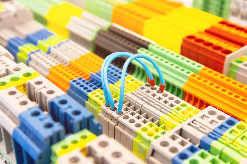
Feed-Through Terminal Blocks
Feed-through terminal blocks provide a direct connection between two conductors through a common current path. They are the basic building block of many DIN rail terminal blocks and are used for routing power, control, and signal conductors through a panel.
Their simplicity makes them a useful reference for understanding other terminal block types. The selection still depends on conductor cross-section, rated current and voltage, insulation requirements, mounting system, and the required wire termination method.
Ground Terminal Blocks
A ground terminal block provides a connection between a protective conductor and the grounding system. DIN rail versions typically establish electrical continuity to the mounting rail or another designated grounding conductor while maintaining mechanical retention.
Protective-conductor terminals are subject to specific short-circuit and mechanical requirements because the connection may have to carry fault current for the duration required to operate the protective device. This makes the grounding function fundamentally different from an ordinary signal or feed-through connection.
Fused Connection Terminal Blocks
Fused connection terminal blocks combine conductor termination with a replaceable fuse in a single assembly. This places overcurrent protection close to the circuit being protected and can reduce panel space compared with separate terminal and fuse-holder arrangements.
The fuse rating must be coordinated with the conductor, load, and upstream protection. Some designs also incorporate visual indicators that identify an open fuse, which can reduce troubleshooting time in densely wired panels.
For circuits requiring resettable protection, circuit breakers may be installed alongside the terminal strip rather than incorporating a fuse into the terminal itself.
Disconnect Terminal Blocks
Disconnect terminal blocks allow a circuit to be opened without removing the conductor from its termination point. Depending on the design, isolation may be achieved with a sliding link, lever, removable plug, or other disconnect mechanism.
This is useful for instrumentation and control circuits where technicians may need to isolate a field device, perform measurements, or inject a test signal. The key advantage is serviceability: the conductor remains terminated while the circuit is interrupted.
Multi-Level Terminal Blocks
Multi-level terminal blocks place two or more electrically isolated connection levels within a single mounting position. They increase wiring density when several conductors associated with the same device must be terminated within limited panel space.
A two-level terminal can, for example, accommodate separate signal and return conductors, while a three-level configuration can provide additional connections without consuming three conventional terminal positions. The practical trade-off is reduced access compared with single-level terminals, making labeling and test access important during selection.
Barrier Terminal Blocks
Barrier terminal blocks, also called barrier strips or barrier terminal strips, use individual terminal positions separated by insulating barriers. Many designs use a screw clamp and accept ring or fork terminals.
The barrier geometry provides physical separation between adjacent circuits and can be useful where larger conductors, lugged terminations, or greater spacing are required. Unlike a DIN rail terminal assembly, a barrier strip is typically mounted directly to a panel or enclosure rather than clipped onto a DIN rail.
For high-current wiring, the ability to accept a specified ring or fork terminal can be an important selection criterion. The terminal's rated conductor range and the lug dimensions must both be compatible with the installation.
Pluggable Terminal Blocks
A pluggable terminal block separates the fixed connection point from the removable wiring section. A header remains mounted to the equipment, while a plug carries the conductors and can be removed as a unit.
This arrangement is valuable when equipment must be replaced or serviced without individually disconnecting every conductor. It also supports modular equipment construction, provided the plug and header have compatible current, voltage, mating cycle, and environmental ratings.
PCB Terminal Blocks
PCB terminal blocks provide a field-wiring interface directly to a printed circuit board (PCB). The wire-side connection may use a screw clamp, spring clamp, or another termination method, while the board-side connection uses pins that are mechanically and electrically connected to the PCB.
The interface therefore has two distinct requirements: the wire connection must meet the electrical and mechanical requirements of the field conductor, while the PCB connection must withstand soldering, mechanical loading, thermal cycling, and the electrical current carried through the board traces and terminal pins.
Recommended reading: Types of PCB Connectors: An In-Depth Guide.
Thermocouple Blocks
Thermocouple blocks require a different approach because the terminal itself can become part of the measurement circuit. A thermocouple generates a voltage based on the temperature difference between its measurement junction and reference junction. Introducing dissimilar metals at the termination point can therefore create additional thermoelectric junctions.
For accurate thermocouple lead connections, the terminal materials and temperature distribution around the connection must be controlled. Isothermal terminal designs minimize temperature gradients between adjacent connections, while a cold-junction sensor provides the reference temperature required for compensation.
This is why a conventional terminal block cannot automatically be treated as electrically neutral in a thermocouple circuit. The termination hardware, conductor materials, and thermal environment can all contribute to measurement error.
Functional Comparison
Terminal block type | Primary function | Typical application | Key selection consideration |
Feed-through | Direct conductor-to-conductor connection | Power and control wiring | Current, voltage, conductor size |
Ground | Protective conductor connection | Protective grounding | Fault-current withstand and grounding continuity |
Fused | Connection plus circuit protection | Instrument and control circuits | Fuse type, rating, and accessibility |
Disconnect | Circuit isolation without wire removal | Instrumentation and testing | Isolation method and test access |
Multi-level | Increase wiring density. | High-density control panels | Accessibility and labeling |
Barrier | Separated screw termination points | Panel and equipment wiring | Spacing, lugs, current rating |
Pluggable | Removable wiring interface | Modular equipment | Mating rating and serviceability |
PCB | Wire-to-board connection | Electronic and control equipment | PCB mounting and board-current capacity |
Thermocouple | Temperature-signal termination | Temperature measurement | Thermoelectric compatibility and thermal gradients |
Recommended reading: Thermistor vs Thermocouple: Which Temperature Sensor Suits Your Engineering Needs?
Reading the Ratings: UL 1059 versus IEC 60947-7-1
A terminal block can carry different current and voltage ratings under UL and IEC standards. These values should not be treated as competing specifications for the same test. Each rating belongs to a different evaluation framework, so the applicable standard must be identified before a rating is used for design.
Voltage Rating
Voltage rating is closely tied to the terminal's insulation system and the distances between conductive parts. Two dimensions are important:
Clearance is the shortest distance through air between conductive parts.
Creepage is the shortest distance along the surface of an insulating material.
These distances, together with the insulation system and required dielectric withstand, determine the voltage for which the terminal can be used under the applicable standard. Pollution degree and overvoltage category also affect the insulation requirements in IEC-based applications.
Current Rating
The current rating is primarily a thermal limitation. Current flowing through the terminal produces heat according to:
P = I²R
where P is power dissipated as heat, I is current, and R is the electrical resistance of the connection.
The terminal's conductive materials, contact resistance, geometry, conductor size, and heat dissipation therefore affect its allowable current. UL and IEC evaluation methods use different rating criteria and test conditions, so the resulting values can differ even for the same physical terminal.
A Practical Example
The Phoenix Contact UT 2,5 illustrates why the distinction matters. The standard version is a 2.5 mm² feed-through terminal block with a nominal IEC rating of 24 A at 1,000 V. Its specified conductor range is 0.14 to 4 mm², and the manufacturer lists 32 A as the maximum load current when a 4 mm² conductor is used.
For the same product, the cULus Recognized rating is 20 A at 600 V for 26–12 AWG conductors. The VDE and IECEE entries retain the 24 A, 1,000 V rating under their respective approval information.
Parameter | UL 1059 / North American approval | IEC-based rating | Example: Phoenix Contact UT 2,5 |
Voltage | Determined within the applicable UL evaluation and approval conditions | Influenced by clearance, creepage, insulation system, pollution degree, and overvoltage category | 600 V cULus vs. 1,000 V IEC/VDE |
Current | Determined from the applicable thermal test conditions | Determined from the applicable thermal and power-dissipation requirements | 20 A cULus vs. 24 A IEC/VDE |
Conductor range | Specified in the approval entry | Specified by the terminal's IEC connection data | 26–12 AWG / 0.14–4 mm² |
Approval | Use the rating associated with the applicable North American certification. | Use the rating associated with the applicable IEC/VDE/other approval. | Multiple ratings for the same physical block |
The important point is that the highest number on the datasheet is not automatically the usable rating. A terminal installed in a North American application must be evaluated against the applicable UL or CSA approval data, while an IEC-based installation must use the relevant IEC rating and installation conditions. The UT 2,5 example demonstrates why selecting a component solely from its headline voltage or current value can produce an incorrect design basis.
Insulation and Installation Conditions
IEC selection requires more than reading the nominal voltage. Pollution degree describes the expected contamination of the insulation environment, while overvoltage category establishes the transient overvoltage conditions the insulation system must withstand. The terminal's creepage and clearance must be adequate for those conditions.
For example, the UT 2,5 is specified for pollution degree 3 and overvoltage category III, with an 8 kV rated surge voltage. Its manufacturer also specifies an insulating material group and other insulation characteristics as part of the product data.
These parameters become important when terminal blocks are used in industrial environments where dust, moisture, condensation, or switching transients can reduce the effective insulation margin.
Recommended reading: PCB Layers: Everything You Need to Know
Short-Circuit Withstand
Short-circuit withstand is a separate consideration from the continuous current rating. A terminal may carry a specified continuous current without being capable of withstanding the prospective short-circuit current of the installation.
The relevant question is therefore not simply
Can the terminal carry the normal load current?
It is also
Can the terminal withstand the fault current for the time required by the protective device?
Manufacturers may publish short-time withstand values based on standardized tests and specific conductor configurations. These values must be evaluated together with the upstream circuit breakers, fuses, conductor size, and fault-clearing time rather than treated as a standalone terminal rating.
The selection process should therefore establish four separate limits: continuous current, working voltage, insulation withstand, and short-circuit withstand. A terminal block is suitable only when its ratings satisfy the conditions of the actual installation.
Mechanical Selection: Pitch, Wire Gauge, and Mounting
Once the connection technology and electrical ratings are established, the terminal must physically fit the conductor, mounting system, and available installation space. Three parameters dominate this part of the selection: pitch, conductor range, and mounting configuration.
Pitch
Pitch is the center-to-center distance between adjacent terminal positions. It determines the physical density of the assembly and contributes to the available creepage and clearance between conductive parts.
Smaller pitch allows more circuits to occupy a given length of terminal strip, but the reduction in spacing can constrain insulation distances, conductor size, and voltage rating. Larger pitch generally provides more space around each connection and may accommodate larger conductors or higher electrical ratings.
For PCB terminal blocks, common pitches include 3.50, 3.81, 5.00, 5.08, 7.50, 7.62, 10.00, and 10.16 mm. The correct pitch is ultimately determined by the PCB footprint and the terminal's electrical and mechanical requirements; similar nominal ratings do not make different pitches interchangeable.
Wire Gauge and Conductor Range
The specified wire gauge range is both a minimum and a maximum. The conductor must be large enough for the clamping mechanism to establish the specified contact and small enough to fit securely within the terminal.
Conductor preparation can further change the allowable range. A terminal may accept a larger bare stranded conductor than it accepts with a ferrule or permit a smaller cross-section when two conductors share the same connection point. These limitations are product-specific and must be taken from the manufacturer's connection data.
The number of conductors per terminal also matters. A terminal rated for one conductor of a particular cross-section cannot automatically be assumed suitable for two conductors of the same size. Multiple conductors can alter clamping geometry, contact pressure, current distribution, and heat dissipation.
For that reason, selection should verify all applicable combinations:
conductor material and construction;
solid or stranded conductor;
conductor cross-section or AWG;
ferruled or unferruled termination;
number of conductors per connection;
allowable insulation diameter; and
applicable current rating for that configuration.
DIN Rail Mounting
For modular panel installations, DIN rail terminal blocks are commonly mounted on standardized rails. IEC 60715 defines dimensional and functional requirements for rails used to mount switchgear, controlgear, and accessories.
The 35 mm rail is widely used in industrial control equipment, including common TS35 profiles. Rail selection still matters because the terminal must have a compatible mounting foot, and the rail assembly must provide adequate mechanical support.
Rail dimensions can also affect the overall installed height of the terminal. This becomes relevant when enclosure depth, wire duct placement, or adjacent equipment limits the available space.
Terminal Width and Wiring Density
Terminal width determines how much mounting space a group of connections consumes. For a uniform terminal assembly:
Rail length ≈ (Number of positions × terminal width) + accessory allowance
End covers, separators, markers, jumpers, and other accessories must be included in the actual layout rather than treating the nominal terminal width as the complete footprint.
For example, 100 terminal positions at 5.2 mm each require:
100 × 5.2 mm = 520 mm
before accounting for end covers and other accessories. This is more than half a meter of mounting space, which illustrates why terminal width becomes significant in high-density marshalling applications.
Protection Against Electric Shock
Mechanical selection also includes protection against accidental contact with energized conductive parts. The terminal's enclosure and geometry should provide the required degree of finger and back-of-hand protection for the installation.
Where terminals may be accessible during operation or maintenance, additional covers or barriers may be required. Protection should be evaluated as part of the complete installation rather than assumed from the presence of an insulating housing alone.
The final mechanical check is therefore straightforward: the terminal must fit the conductor, mounting system, enclosure, wiring space, and required access conditions simultaneously.
Terminal Block Mechanical Selection Checklist
Parameter | Selection check |
Pitch | Match the PCB footprint and required creepage/clearance spacing. |
Terminal width | Fit the available DIN rail or panel space. |
Wire gauge | Stay within the specified conductor range. |
Conductor type | Verify compatibility with solid, stranded, or flexible conductors. |
Ferrule | Confirm the allowable ferrule size and termination configuration. |
Multiple conductors | Verify the permitted number and cross-section per connection point. |
Mounting | Confirm compatibility with DIN rail, panel, PCB, or other support. |
Enclosure clearance | Allow sufficient height, depth, and wiring space for installation and service. |
Touch protection | Confirm the required level of protection against accidental contact. |
Wiring a Terminal Block Correctly
Even a correctly selected terminal block can fail if you prepare or terminate the conductor improperly. The exact procedure depends on the connection technology, but the following sequence applies to screw-clamp terminal blocks. Spring-clamp and push-in designs eliminate the screw-torque step but still require correct conductor preparation and insertion.
Strip the conductor to the specified length. Use the terminal block manufacturer's specified stripping length rather than estimating by eye. For example, the Phoenix Contact UT 2,5 specifies a 9 mm stripping length. Excessive stripping can leave bare conductor exposed beyond the clamping area, increasing the risk of contact with adjacent terminals or conductive surfaces. National Instruments specifies a maximum 7 mm strip length for its SCXI-1303 and warns against leaving bare wire exposed beyond the screw terminal.
Determine whether a ferrule is appropriate. A ferrule is a crimped metal sleeve that consolidates the strands of a flexible conductor before insertion into the terminal. It can simplify insertion and prevent strand spread, but its use depends on the terminal design, conductor type, and applicable requirements. Some push-in terminal blocks specify ferrules for small or flexible conductors, while other applications permit direct termination without one. Always verify the manufacturer's allowable conductor and ferrule combinations.
Use the correct ferrule and crimping method. Ferrules are not interchangeable simply because they fit over the conductor. DIN 46228 defines ferrule requirements, including versions with and without plastic collars. Crimp geometry also needs to match the terminal's conductor entry. Trapezoidal, square, and hexagonal crimps produce different cross-sectional shapes and are suited to different connection compartments. The crimp should fully capture the conductor strands without damaging the ferrule or leaving loose strands exposed.
Insert the conductor fully into the clamping unit. The conductor should reach the intended contact position without insulation entering the electrical contact area. Unless the terminal block is specifically designed for multiple conductors, use one conductor per clamping unit. Where multiple conductors are permitted, verify the manufacturer's limits for conductor size, type, and quantity.
Apply the specified torque where required. For screw terminal blocks, use the manufacturer's specified torque and a suitable torque-controlled tool. The Phoenix Contact UT 2,5, for example, specifies 0.5–0.6 N·m for its M3 screw connection. Torque that is too low can produce inadequate contact pressure and increased resistance; excessive torque can damage the conductor, terminal, or clamping mechanism. In installations governed by the NEC, 110.14(D) requires torque-controlled installation where the equipment manufacturer provides a numerical torque value.
Inspect the completed termination. Check that the conductor is fully inserted, insulation is not clamped where it should not be, no strands are exposed, and the terminal shows no visible damage or deformation. Verification should occur before energizing the circuit.
Do not routinely retorque a correctly installed connection. Correct initial torque is the objective, not repeated tightening as preventive maintenance. NEMA guidance recommends using visual inspection and infrared scanning to identify abnormal heating or connection problems rather than routinely re-torquing energized equipment. If a connection must be checked, follow the applicable manufacturer's procedure and work on a de-energized circuit where required.
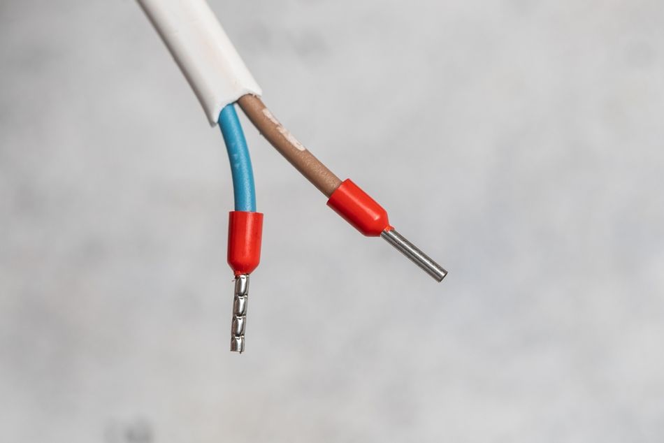
A reliable wire termination therefore depends on more than tightening a screw. Strip length, conductor preparation, ferrule selection, insertion depth, clamping force, and final inspection all contribute to the integrity of the electrical connection.
Recommended Reading: How to Solder Wires: Comprehensive Guide for Engineers
Failure Modes, Limitations, and Troubleshooting
Terminal block failures rarely begin as sudden events. Many develop from poor termination, mechanical stress, environmental exposure, or operation outside the specified electrical limits. Understanding the failure mechanism makes troubleshooting more effective.
Loose terminations increase resistance and heat. An improperly torqued connection can develop higher contact resistance over time. As current passes through the connection, the resulting heat follows:
P = I²R
As resistance increases, more heat is generated at the connection. Sustained heating can degrade the terminal, conductor insulation, and surrounding components. Oxidation at an inadequately compressed joint can increase resistance further, creating a reinforcing cycle of resistance and heating. A high-resistance connection can also produce an unwanted voltage drop that affects equipment operation.
Vibration and thermal cycling can reduce connection integrity. Repeated mechanical movement and temperature changes can challenge the clamping system. Screw-clamp designs may use mechanical locking features or conductor protection elements, while spring-clamp designs maintain contact force through a preloaded spring. The appropriate solution depends on the terminal block design and the application's vibration and temperature environment. Qualification data such as vibration and shock testing should be reviewed when selecting terminal blocks for mobile, industrial, or high-vibration equipment.
Fine-stranded conductors require appropriate termination. Tightening a screw directly onto a flexible conductor can spread or damage individual strands if the terminal is not designed for that termination method. A wire guard, suitable ferrule, or other approved conductor-preparation method can prevent strand damage. The correct approach depends on the terminal's connection technology and manufacturer's specifications.
Corrosion can increase contact resistance. Moisture, contaminants, and unsuitable material combinations can degrade the contact interface. Terminal designs may address this through contact geometry, plating, spring force, and materials selected to maintain a stable interface under the expected environmental conditions. For corrosive environments, the terminal's environmental ratings and material compatibility should be evaluated rather than relying on the appearance of the connection alone.
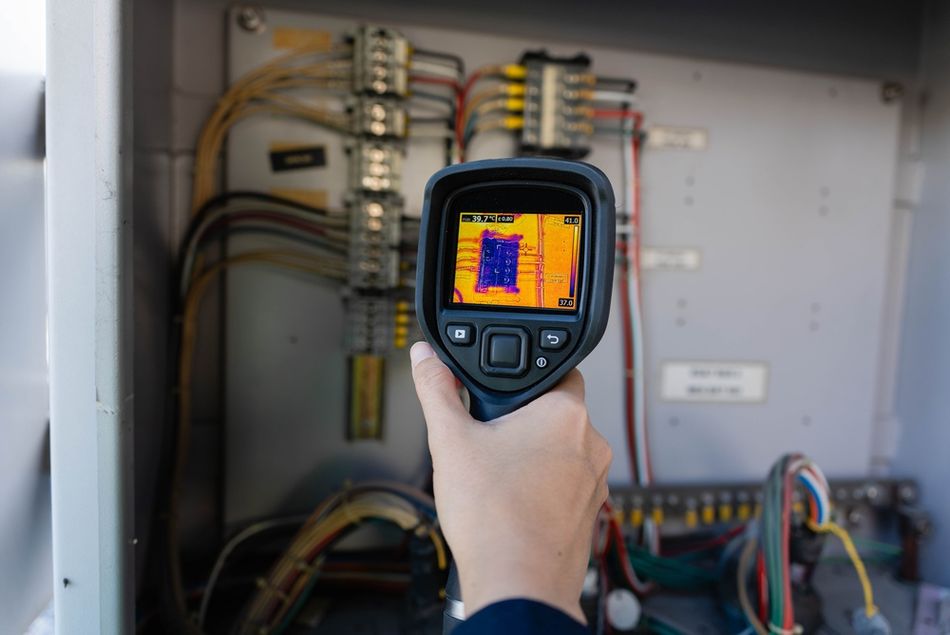
Troubleshoot using measurable evidence. A loose or degraded connection should not be diagnosed by touch alone. A voltage-drop measurement can identify excessive resistance across a connection, while infrared inspection can reveal localized heating under load. Visual inspection can also identify discoloration, damaged insulation, loose hardware, corrosion, or other signs of deterioration. Measurements should be made using procedures appropriate to the equipment's voltage, energy level, and applicable safety requirements.
Failure mode | Typical mechanism | Diagnostic indication | Selection or maintenance response |
Loose termination | Insufficient or incorrect clamping force | Localized heating, voltage drop | Apply specified termination torque. |
Vibration | Mechanical movement or loss of contact force | Intermittent operation, resistance change | Select an appropriate locking or spring-clamp design. |
Thermal cycling | Repeated expansion and contraction | Connection degradation over time | Verify temperature rating and connection technology. |
Strand damage | Improper termination of flexible conductor | Broken or displaced strands | Use an approved termination method or ferrule. |
Corrosion | Moisture, contaminants, or material incompatibility | Oxidation, increased resistance | Verify environmental rating and material compatibility. |
Overheating | Excess current or high contact resistance | Discoloration, insulation damage | Verify current rating, conductor size, and termination quality. |
Recommended reading: Step-by-Step Guide To Troubleshooting Electrical Motors
Terminal Block, Bus Bar, Power Distribution Block, or Wire Nut
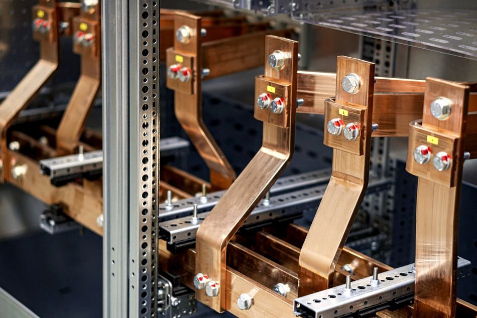
Terminal blocks, bus bars, power distribution blocks, and wire connectors can all connect or distribute conductors, but they are not interchangeable. The differences are in their construction, insulation, connection capacity, mounting, protection, and applicable product standards.
A bus bar is a conductive bar used to distribute a common electrical potential to multiple connections. It may be bare or insulated and is often used where high current or compact power distribution is required. A terminal block can also distribute a common potential when multiple clamping units are electrically connected through a shared current bar. The terminal block provides an insulated housing and can accommodate accessories such as jumpers, markers, test points, and covers.
A power distribution block is designed specifically to divide an incoming conductor or conductors into multiple outgoing circuits. In North America, UL 1953 covers power distribution blocks rated up to 1,000 V. The standard addresses devices with connectors mounted on an insulating base, with provisions for incoming conductors and multiple tap-off conductors.
This distinction matters in applications where the installation standard requires specific spacing, enclosure, or listing conditions. A terminal block recognized under UL 1059 is not automatically equivalent to a power distribution block evaluated under UL 1953. The applicable product marking, use group, voltage, current, conductor configuration, and installation requirements must be verified for the intended application.
A wire connector, such as a twist-on connector, serves a different purpose. UL 486C covers splicing wire connectors, including twist-on, spring-action, insulation-piercing or displacement, crimp, and mechanical set-screw types within its applicable scope. These devices are intended primarily to join or splice conductors rather than provide a structured termination interface for a control panel.
The practical distinction is serviceability. Terminal blocks can provide standardized identification, test access, bridging, disconnect functions, and organized conductor routing. A wire connector can make a reliable splice, but it generally does not provide the same modular interface for testing, isolation, labeling, and maintenance.
Device | Primary function | Typical installation | Key advantage | Main limitation |
Terminal block | Terminate, join, or distribute conductors. | Control panels, machinery, DIN rail assemblies | Modular, serviceable, configurable | Requires appropriate mounting and accessories |
Bus bar | Distribute a common electrical potential. | Power distribution assemblies, switchgear | High-current distribution and compact layout | Requires appropriate insulation/guarding and mounting |
Power distribution block | Split incoming power into multiple outgoing circuits. | Panels and power distribution equipment | Organized multi-conductor distribution | Must meet applicable listing, spacing, and rating requirements |
Wire connector | Splice or join conductors. | Junctions, equipment wiring, field connections | Simple and compact | Limited test, disconnect, and identification capability |
For power distribution, the correct choice depends on more than the number of conductors. Evaluate current and voltage ratings, conductor size, short-circuit withstand, spacing, insulation, mounting method, applicable certification, and the installation standard. A device that can electrically connect the conductors is not necessarily suitable for the installation.
Common Mistakes
Several selection and installation errors can undermine an otherwise suitable terminal block. The most common are:
Using the IEC rating for a UL application. A terminal block can carry different ratings under different approval systems. For example, the Phoenix Contact UT 2,5 is rated 24 A at 1,000 V under its IEC data but 20 A at 600 V under its UL Recognized data. The applicable certification and installation requirements determine which rating governs.
Ignoring multi-conductor derating. The allowable conductor size can change when multiple conductors share one clamping unit. For UT 2,5, the permitted configuration for two conductors differs from the single-conductor configuration. Always verify the manufacturer's connection data for the actual number and size of conductors being installed.
Treating a UL Recognized terminal block as a listed power distribution block. Recognition under UL 1059 does not automatically make a terminal block suitable for every power-distribution or field-wiring application. Spacing, use groups, enclosure requirements, and conditions of acceptability can differ from those applicable to products evaluated for the intended installation.
Retorquing connections as routine maintenance. A correctly installed connection should not be routinely tightened simply because it is on a maintenance schedule. Follow the manufacturer's maintenance instructions and use visual inspection, thermal imaging, or electrical measurements where appropriate to identify developing connection problems.
Using a standard feed-through block for thermocouple connections. A thermocouple circuit depends on controlled thermoelectric junctions. An unsuitable terminal block can introduce unintended junctions and temperature gradients, creating measurement errors. Thermocouple terminal blocks should maintain appropriate material compatibility and the conditions required for the measurement system's cold-junction compensation.
Ignoring inrush and transient conditions. A terminal block selected only from the steady-state current may not be suitable for circuits with high inrush current or recurring transient overvoltage. Evaluate the expected duration, magnitude, repetition, and source of the transient against the terminal block's electrical and thermal ratings rather than simply selecting a larger physical size.
Conclusion
Terminal block selection is ultimately a matter of matching the connection, circuit, rating, and installation environment.
Start with the connection technology: screw clamp, spring clamp, push-in, IDC, or another mechanism suited to the installation's conductor type, vibration exposure, wiring volume, and service requirements. Next, select the functional type required by the circuit, whether feed-through, ground, fused, disconnect, multi-level, barrier, pluggable, or PCB-mounted.
Then verify the applicable rating basis. UL and IEC ratings are not interchangeable numbers; the applicable standard, voltage, current, conductor configuration, insulation requirements, and short-circuit conditions determine which ratings govern the installation.
Finally, confirm the mechanical fit. Pitch, wire gauge, conductor preparation, mounting system, terminal width, enclosure clearance, and touch protection all need to work together.
The part number should be the result of that process, not the starting point. For critical applications, validate the selected terminal block under conditions representative of the complete assembly, including the expected electrical load, conductor configuration, temperature, vibration, and available heat dissipation.
Frequently Asked Questions
What is a terminal block used for?
A terminal block provides a fixed point for connecting and mechanically securing conductors. IEC 60947-7-1 defines terminal blocks as devices that provide electrical and mechanical connections between copper conductors while being fixed to a support.
What is the difference between a terminal block and a bus bar?
A bus bar is a conductive bar used to distribute a common electrical potential. A terminal block can perform a similar distribution function when multiple clamping units share a common current bar, but it also provides an insulated housing and can accommodate accessories such as markers, jumpers, covers, and test points.
Are screw terminals better than push-in terminals?
Neither is universally better; they address different installation requirements. Screw terminals rely on applied torque to generate clamping force, while push-in designs use a spring contact to secure the conductor. The appropriate choice depends on conductor type, installation speed, vibration, service requirements, conductor preparation, and the manufacturer's specified connection range.
Are terminal blocks better than wire nuts?
They serve different purposes. A twist-on wire connector is primarily a conductor-splicing device covered by UL 486C within its applicable scope. A terminal block provides a structured termination interface that can be mounted to a DIN rail, panel, or PCB and can incorporate labeling, testing, bridging, and disconnect functions. The appropriate choice depends on the installation and applicable requirements.
What is the difference between a spring-loaded terminal and a screw terminal?
The main difference is how clamping force is generated. A spring terminal uses a preloaded spring to maintain contact force, while a screw terminal relies on the torque applied to its clamping mechanism. This makes correct torque and conductor preparation important for screw connections.
How do I know which terminal block to use?
Start with the circuit's voltage, continuous current, conductor size, number of circuits, and environmental conditions. Then select the required terminal block function, connection technology, mounting method, and conductor configuration. Finally, verify the applicable UL, IEC, or other certification and the ratings for the actual installation conditions.
How do you wire a terminal block?
Strip the conductor to the specified length, prepare the conductor as required, insert it fully into the clamping unit, and apply the manufacturer's specified termination method. For screw-clamp connections, use the specified torque. Inspect the completed connection to confirm that no strands or excessive bare conductor are exposed.
Do terminal blocks need ferrules?
Not always. Ferrule requirements depend on the terminal design, conductor type, and applicable installation requirements. Some push-in terminal blocks specify ferrules for small or flexible conductors, while other designs accept stranded conductors directly. Always verify the manufacturer's approved conductor and ferrule combinations.
What size wire fits a terminal block?
There is no single wire size for all terminal blocks. IEC 60947-7-1 covers terminal blocks across a broad conductor range, but each terminal block has its own specified minimum and maximum conductor size. For example, a 2.5 mm² feed-through terminal block may accept approximately 0.14–4 mm² conductors. Always use the manufacturer's connection data for the specific part.
What is a fused terminal block for?
A fused terminal block combines conductor termination with overcurrent protection. The fuse is integrated into the terminal assembly, allowing an individual circuit to be protected and, depending on the design, disconnected or visually monitored from the same location. Fuse type, voltage, current, interrupt rating, and accessibility must match the application.
What certifications should a terminal block carry?
The required certification depends on the market, installation, and application. In North America, UL 1059 recognition or listing may apply, depending on how the terminal block is used. IEC-based installations may require compliance with IEC 60947-7-1. Additional approvals may apply to railway, marine, hazardous-area, or other specialized environments. The marking and rating must correspond to the actual installation requirements.
References
[1] International Electrotechnical Commission, IEC 60947-7-1:2025, Low-Voltage Switchgear and Controlgear—Part 7-1: Ancillary Equipment—Terminal Blocks for Copper Conductors, 4th ed. Geneva, Switzerland: IEC, 2025. https://webstore.iec.ch/en/publication/72949
[2] Underwriters Laboratories, UL 1059, Standard for Terminal Blocks, 6th ed. Northbrook, IL, USA: UL Standards & Engagement, 2024.
[3] N. Hadziefendic, J. Trifunovic, and M. Kostic, “Effects of a reduced torque on heating of electrical contacts in plugs and receptacles,” IEEE Trans. Compon., Packag. Manuf. Technol., vol. 8, no. 11, pp. 1905–1913, Nov. 2018, doi: 10.1109/TCPMT.2018.2827080.
[4] E. Fjeld, W. G. J. Rondeel, G. K. Sønsteby, F. W. Bekken, and T. R. Eriksen, “Contact resistance and temperature rise of cable connections in cable distribution cabinets,” in Proc. 66th IEEE Holm Conf. Electr. Contacts (HLM), 2020, doi: 10.1109/HLM49214.2020.9307905.
[5] P. Roccato, L. Bellavia, P. P. Capra, L. Cinnirella, et al., “Influence of crimped connections in temperature rise tests,” Meas. Sci. Technol., vol. 31, no. 4, 2020, doi: 10.1088/1361-6501/ab5824.
[6] M. Zhou, F. Lan, and Z. Kong, “The influencing factors of contact resistance of busbar connectors,” in Proc. 16th IET Int. Conf. AC and DC Power Transmission (ACDC), 2020, doi: 10.1049/icp.2020.0329. https://ieeexplore.ieee.org/document/9537992
[7] Y. [et al.], “Electrical contact resistance of connector response to mechanical vibration environment,” IEEE Trans. Compon., Packag. Manuf. Technol., 2019. https://ieeexplore.ieee.org/document/8801871
[8] J. Bian, W. Wang, and Z. He, “Insertion-withdrawal, contact behavior, and temperature rise of a cantilevered reed-type electrical connector,” IEEE Access, vol. 14, pp. 60907–60921, 2026, doi: 10.1109/ACCESS.2026.3684887. IEEE Xplore/DOI record
in this article
1. Key Takeaways2. Introduction3. What a Terminal Block Is and Why the Choice Matters4. Connection Technology: The First Decision5. Terminal Block Types: The Functional Taxonomy6. Reading the Ratings: UL 1059 versus IEC 60947-7-17. Mechanical Selection: Pitch, Wire Gauge, and Mounting8. Wiring a Terminal Block Correctly9. Failure Modes, Limitations, and Troubleshooting10. Terminal Block, Bus Bar, Power Distribution Block, or Wire Nut11. Common Mistakes12. Conclusion13. Frequently Asked Questions14. References