Motor Control Circuit Guide: Contactors and Wiring
Design, wire, protect, and troubleshoot motor starting systems.

10 Jul, 2026. 11 minutes read
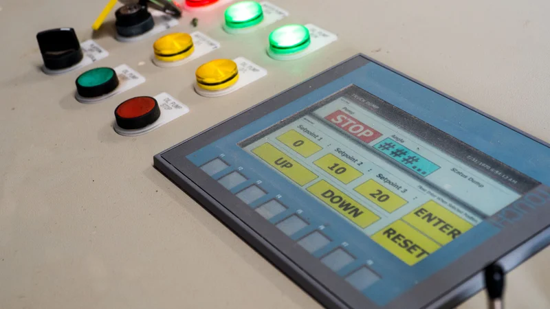
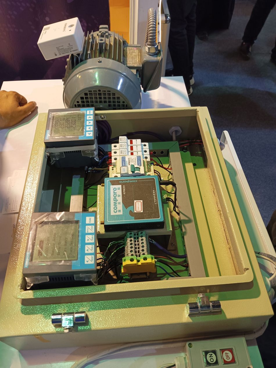
Motor Controller box in an industrial setup
Key Takeaways
A motor control circuit is the command layer; the power circuit is the load-current layer.
Contactors, overload protection, push buttons, and interlocks are the foundation of most industrial starters.
A good wiring diagram shows terminal numbers, device tags, control voltage, coil logic, feedback, and trip paths.
DOL, star-delta starter, soft starter, and VFD designs solve different starting-current, torque, and process-control problems.
PLC integration improves sequencing and diagnostics, but safety and overload trips must remain effective.
Faultfinding is fastest when voltage, continuity, current, and state feedback are tested in a defined order.
What a Motor Control Circuit Does
A motor control circuit starts, stops, reverses, sequences, and protects electric motors. In practice, it may be a basic three-wire start/stop station, a PLC-commanded pump skid, or a motor control center feeding fans, compressors, mixers, and conveyor systems. The same principle applies in each case: contactors or electronic power devices switch energy, while the control path decides when that switching action is allowed.
The design goal is controlled motion, not merely rotation. A professional motor control circuit must respond to operator commands, stop after a trip or permissive loss, avoid unintended restart where the risk assessment requires it, and expose useful diagnostic information. IEC 60947-4-1:2023 applies to low-voltage electromechanical contactors and motor-starters for circuits up to 1000 V AC or 1500 V DC. NFPA 70, National Electrical Code, is the main United States installation code, and Article 430 covers motors, motor branch circuits, controllers, overload protection, motor control circuits, and motor control centers. IEC 60204-1 covers electrical equipment of machines, including programmable systems, control circuit protection, emergency stop, EMC, and technical documentation.
This article is a foundational engineering reference. It distinguishes the command circuit from the power circuit, defines the core devices, explains a DOL wiring diagram, compares major starter configurations, and gives a practical troubleshooting workflow for industrial and automation work.
Control Circuit vs Power Circuit
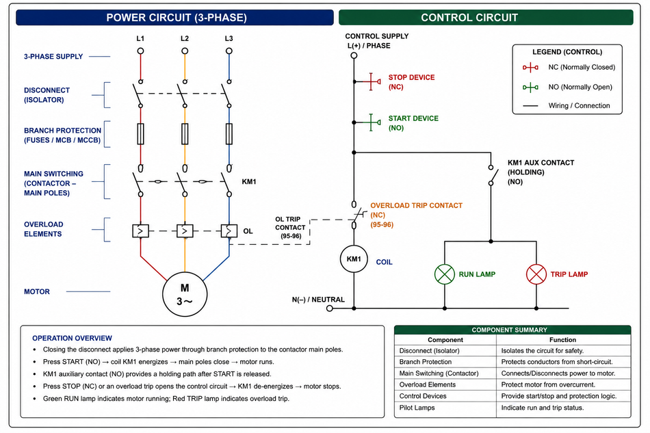
A motor starter is easiest to understand as two coupled circuits. The power circuit carries motor current from the supply to the motor terminals. It includes the disconnect, fuse or circuit breaker, main switching poles, overload current-sensing elements, and conductors sized for load current and fault duty. The control circuit carries command current for coils, relays, lamps, timers, selectors, and controller I/O.
For a common 3-phase motor installation, the load side may be 400 V AC, 480 V AC, or 600 V AC depending on the site. The command side may be 24 V DC from a control supply, 120 V AC from a control transformer, or 230 V AC in some regions. Select the control voltage by coil ratings, plant standards, spare parts, shock-risk policy, and the expected burden of all simultaneously energized devices.
This separation is essential during design review and field service. If the coil is commanded but the motor terminals are dead, the problem is likely in the load path. If the load path is healthy but the coil never receives voltage, the fault is in the command path. The wiring diagram should make that separation visually obvious.
Function | Control-side example | Power-side example | Engineering concern |
Command | Start/stop station, selector, PLC output | Not applicable | Correct logic and anti-restart behavior |
Switching | Coil and interposing relay | Main poles of the starter | Coil voltage, duty, utilization rating |
Protection | Control fuse, trip contact | Fuse, breaker, overload elements | Fault clearing, thermal protection, SCCR |
Feedback | Auxiliary contact, run lamp, digital input | Current transformer, voltage monitor | Confirmed state, not only command state |
Documentation | Ladder wiring diagram | One-line and point-to-point wiring diagram | Maintainable terminals and wire numbers |
Suggested Reading: DC Motor Speed Control: PWM Techniques for Brushed and BLDC Drives
Core Components in Motor Control Circuits
A motor control circuit is a combination of sophisticated parts. Here is a quick look at the core components:
Contactors
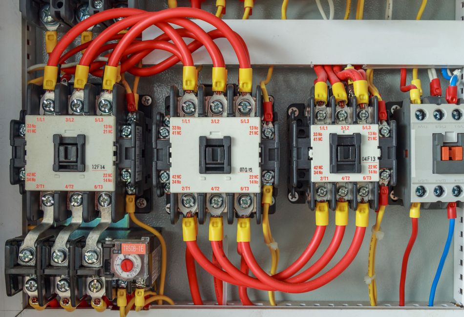
Contactors are electrically operated switching devices intended for repeated operation. A coil magnetizes a frame, pulls in an armature, closes the main contacts, and allows current to flow to the load. When the coil is de-energized, a spring force opens the contacts. Eaton training material describes starters as assemblies made from contactors and overloads: one block switches current, and the other protects the motor from excessive current and heating.
A motor contactor is selected from motor voltage, full-load current, horsepower or kW rating, utilization category, switching frequency, enclosure temperature, available fault current, and manufacturer coordination data. IEC devices are frequently applied by AC-3 duty for squirrel-cage induction motor starting and stopping at speed.
Overload Protection Relays
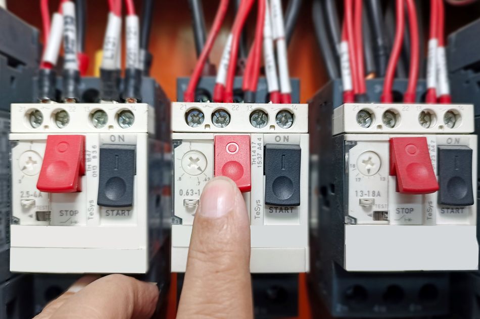
The overload relay protects against sustained overcurrent. It is not a high-fault interrupting device. A thermal overload relay uses a heat-modeling element, while electronic overloads can add phase loss, phase imbalance, ground-fault detection, trip history, and networked diagnostics. Startup current is intentionally tolerated for a short period; Eaton material notes that inrush can be as high as 6 to 8 times running current, so overload devices include time delay before tripping.
Suggested Reading: Contactor vs Relay: Understanding the Differences and Applications
Operator Push Buttons
Operator push buttons provide the local human interface. In a conventional three-wire circuit, the stop button is normally closed and the start button is normally open; the overload trip is another normally closed contact in the permissive chain. A selector or toggle switch may be used for hand-off-auto, jog, or local-remote selection, but maintained controls must be evaluated carefully where automatic restart would create risk.
Interlocks
An auxiliary contact is linked to the main mechanism but used for logic. The most familiar use is the seal-in path around the start device. Other uses include forward/reverse interlocking, run status feedback, permissive chains, and pilot-light indication.
Timers
Timers are used when the circuit needs a defined delay. A transition timer changes a reduced-voltage starter from the starting connection to the running connection. A delay-on or delay-off function can also prevent rapid pump cycling or enforce a dead time before reversing.
Component | Typical role | Common markings | Failure modes to check |
Branch protective device | Isolation and high-fault clearing | QF1, FU1, L1/L2/L3 | Tripped handle, open fuse, loose lug |
Switching device | Remote motor switching | KM1, A1/A2, L1/T1 | Open coil, chatter, welded pole, worn tips |
Thermal overload relay | Motor heating protection | FR1, 95-96 NC, 97-98 NO | Wrong FLA setting, trip, single phasing |
Operator station | Start, stop, reset, mode selection | S0 stop, S1 start, reset | Dirty contact, miswired block, broken actuator |
Auxiliary contacts | Holding, interlock, feedback | 13-14 NO, 21-22 NC | Wrong block, stuck mechanism, loose wire |
Timing relay | Delay, transition, anti-cycle | KT1, timed NO/NC | Wrong range, failed module, bypassed delay |
Pilot lamp | Ready, run, trip indication | H1, H2, H3 | Burned lamp, wrong voltage, misleading status |
Controller I/O | Sequencing and diagnostics | DI, DO, common | Failed output, missing common, wrong I/O type |
Suggested Reading: How Do Time Delay Relays Work?
Reading and Drawing a Wiring Diagram
A motor wiring diagram must show how current flows in each operating state. Ladder format is common for hardwired controls because it resembles relay logic. The left rail is the control supply. The right rail is the return or neutral. Series contacts mean all conditions must be true; parallel paths mean either branch can complete the rung.
A DOL motor starter uses a canonical rung with a normally closed stop contact, a normally closed trip contact, a normally open start contact, and the coil. The seal-in path is wired around the start contact. Pressing start energizes the coil, which closes the holding path. Releasing start does not stop the motor because the holding path remains closed. Pressing stop, losing a permissive, or opening the trip contact drops the coil.
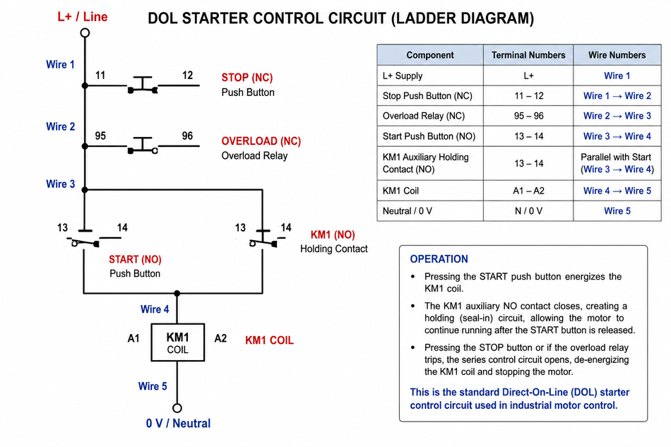
A correct drawing should include device tags, cross-references, terminal numbers, cable IDs, conductor numbers, and state conventions. Use standard tags such as QF1 for the protective device, KM1 for the starter coil, FR1 or OL1 for overload protection, S0 for stop, S1 for start, and M1 for the motor when they match company practice.
A wiring diagram also supports commissioning. Before applying load voltage, energize only the command supply and verify that stop, start, reset, trip, and permissive devices change state as drawn. Only after that should the power path be energized for rotation and load-current tests.
Starter Configurations: DOL, Star-Delta Starter, Soft Starter, and VFD/VSD
A DOL starter applies full line voltage to the motor. It is economical, easy to maintain, and provides high starting torque. The tradeoff is high inrush, mechanical shock, and possible voltage sag. Use it when the supply is stiff enough, the driven machine can tolerate acceleration torque, and utility or facility rules allow the starting current.
Star-Delta Starter
A star-delta starter first connects the windings in star, then changes to delta for running. In star, each winding sees about 58 percent of the line voltage, so the available starting torque is much lower than at full voltage because induction motor torque is approximately proportional to the square of the applied voltage. A conventional implementation uses main, star, and delta switching devices with electrical and mechanical interlocks.
Soft Starter
A soft starter uses semiconductor phase control to ramp voltage and reduce mechanical and electrical stress during acceleration. ABB softstarter documentation compares DOL, star-delta, and soft starting with voltage, current, and torque curves, and identifies problems such as current transients, torque peaks, supply voltage variation, conveyor product damage, and pump water hammer.
This approach is usually best for fixed-speed machines that need smoother starts or stops but do not need continuous speed control.
Variable Frequency Drives
A variable frequency drive, or VFD/VSD, rectifies AC to a DC link and synthesizes a variable-frequency output. It can regulate speed, acceleration, deceleration, and torque. ABB describes variable speed drives as a way to control mechanical power in industrial processes, especially AC drive systems.
Use a drive for fans, pumps, extruders, mixers, hoists, and processes where energy optimization or process regulation matters. Evaluate harmonics, EMC, motor insulation, cable length, braking, bypass strategy, and safe torque off.
Starter type | Primary method | Strengths | Limitations | Good fit |
DOL | Full-voltage switching | Low cost, high torque, simple wiring diagram | High inrush, mechanical shock | Small pumps, fans, simple machines |
Star-delta starter | Reduced-voltage start, timed transition | Lower start current than DOL | Low start torque, transition transient | Light-load medium motors |
Soft starter | Semiconductor voltage ramp | Smooth start/stop, lower shock | No continuous speed regulation | Pumps, compressors, conveyors |
Variable frequency drive | Variable voltage and frequency | Speed control, diagnostics, efficiency potential | Higher cost, harmonics, parameter management | HVAC, process lines, synchronous and induction motors |
Suggested Reading: Motor Speed Control: Methods Across Motor Types
PLC Control, Programmable Logic Controllers, and MCC Integration
A PLC moves sequencing from hardwired relay chains into software, but it does not remove field wiring. Inputs monitor start requests, stop requests, trip state, run feedback, selector position, guard status, and process permissives. Outputs energize coils, interposing relays, lamps, solenoids, or drive commands. IEC 61131-3:2025 defines programming languages for programmable controllers, including ladder diagram, function block diagram, structured text, and sequential function chart.
A conservative architecture keeps safety-critical stop functions and overload trips effective even if the standard controller, output module, or network fails. Depending on the risk assessment, a safety relay or safety PLC may remove power from coils or drive safe-torque-off inputs, while the standard automation system handles sequencing and alarms.
A common I/O model is shown below.
Signal | Direction | Example tag | Purpose |
Start request | Input | PB_START_M1 | Operator command |
Stop request | Input | PB_STOP_M1 | Normal stop command |
Trip status | Input | OL1_TRIP | Fault and restart inhibit |
Run feedback | Input | KM1_FB | Confirms pulled-in state |
Run command | Output | M1_RUN_CMD | Energizes the coil path |
HMI state | Internal | M1_RUNNING | Command plus feedback validation |
In a motor control center, each bucket or compartment may contain a feeder, starter, drive, metering, control terminals, and network connection. MCC design improves maintainability by standardizing disconnects, interlocks, short-circuit current ratings, spare capacity, and isolation practices. The underlying schematic remains the same: incoming protection, load switching, motor protection, command logic, feedback, and documentation.
Protection, Commissioning, and Troubleshooting
Protection must be layered because electrical faults have different time scales. High-current faults require fast interruption by the branch protective device selected for available fault current and equipment SCCR. Overload protection is slower because the motor must accelerate through inrush without nuisance tripping. The command side also needs protection for small conductors, transformer secondaries, relay contacts, and output modules.
Do not confuse a jam with a bolted fault. An overloaded conveyor may draw moderately high current for many seconds because of excess product or a failing bearing. A phase-to-phase fault can rise to thousands of amperes and must be cleared by the feeder protection. Draw both protective functions explicitly.
Voltage sag is a system concern. A large full-voltage start can depress the local bus enough to drop out coils, reset control supplies, dim lighting, or disturb instrumentation. Mitigations include sequential starting, reduced-voltage starting, electronic ramping, larger supply capacity, stronger feeders, and undervoltage ride-through where appropriate.
Commissioning should follow a measured sequence. Verify isolation, conductor torque, grounding, and insulation condition according to site procedure. Energize the command supply first and compare every input state with the wiring diagram. Bump the motor briefly to confirm rotation on a 3-phase motor, then correct phase sequence if needed. Measure line voltage and phase current under real load. Finally, test stop, trip, reset, and loss-of-control-power behavior before release to operations.
Troubleshooting a no-start condition starts at the coil. If the rated coil voltage is absent during a valid command, trace upstream through stop, trip, permissive, selector, controller output, and command-supply protection. If coil voltage is present but the mechanism does not pull in, suspect an open coil, wrong coil voltage, mechanical binding, or a failed interposing relay. If the starter pulls in but the motor does not run, move to the load side and measure line and load terminals before testing the motor leads.
Recommended Reading: Field Oriented Control (FOC) for AC Motors
Conclusion
A reliable motor control circuit combines switching hardware, protective coordination, clear drawings, and disciplined testing. Contactors remain central because they provide robust remote switching and visible circuit state in many industrial systems. Their effectiveness depends on correct overload settings, well-wired command logic, verified stop paths, and a wiring diagram that maintenance personnel can trust.
Future installations will use more electronic overloads, smart starters, Ethernet-connected MCCs, condition monitoring, functional safety integration, and drive-based diagnostics. The fundamentals will remain stable: separate control from power, select devices from real motor and fault data, protect against overload and high-current faults, verify every stop function, and document every terminal. Contactors and the motor control circuit will continue to translate electrical logic into controlled mechanical work.
FAQ
1. What is the difference between a motor control circuit and a power circuit?
The motor control circuit contains command logic: stop devices, start devices, coils, relays, timing functions, controller outputs, and feedback contacts. The power circuit carries load current from the supply through protection and switching hardware to the motor terminals. The command side may be 24 VDC or 120 VAC, while the load side may switch a 3-phase motor at a much higher facility voltage. The same distinction applies to each 3-phase motor in a multi-axis machine.
2. Why is the stop button normally closed?
The stop button is normally closed so the circuit is healthy only when the contact path is intact. Pressing the button opens the path and drops the coil. A broken wire or loose terminal can also open the path, which usually fails toward stopping rather than starting. Safety-rated stop functions require additional design measures beyond an ordinary control contact.
3. What does the seal-in path do in a DOL starter?
The seal-in path is a normally open auxiliary path wired in parallel with the start device. When the coil energizes, this path closes and keeps the coil energized after the operator releases start. Pressing stop or opening the trip contact breaks the series path, de-energizes the coil, and opens the holding path.
4. Is overload protection the same as a breaker?
No. A breaker or fuse clears severe high-current faults. Overload protection protects the motor against sustained current above its safe thermal capacity. The overload function intentionally tolerates normal starting current for a short time, while the high-fault device must interrupt dangerous fault current quickly. A complete design normally includes both functions.
5. When is star-delta starting useful?
Use this method when the motor has six accessible leads, the load can accelerate with reduced torque, and the facility needs lower starting current than DOL without speed control. It is not ideal for high-breakaway-torque machines. Interlocking is critical because simultaneous star and delta closure can create a destructive fault path.
6. When is electronic reduced-voltage starting better than a VFD?
Electronic reduced-voltage starting is often better when the motor runs at fixed speed and the main problem is starting or stopping stress. Examples include pumps, compressors, and conveyors that need smoother acceleration. A VFD is better when the process needs continuous speed control, torque control, energy optimization, reversing control, or richer diagnostics.
7. How should a PLC be used in motor control?
Use the PLC for sequencing, permissives, alarms, operator interface, data collection, and coordination among machines. Monitor actual feedback, not only commands. For example, compare a run command with a feedback input and alarm if the starter does not pull in. Safety and trip functions should remain effective according to the risk assessment.
8. What are the first checks in no-start troubleshooting?
After making the equipment safe to test, check command voltage at the coil during a valid start command. If voltage is missing, trace upstream through stop contacts, trip contacts, permissives, selectors, controller outputs, and fuses. If voltage is correct, check the coil and mechanism. If the device closes, measure the load terminals and then test the motor leads.
References
IEC, IEC 60947-4-1:2023, Contactors and Motor-Starters: Electromechanical Contactors and Motor-Starters.
NFPA, NFPA 70, National Electrical Code (Article 430, Motors).
IEC, IEC 60204-1:2016, Safety of Machinery: Electrical Equipment of Machines, Part 1.
IEC, IEC 61131-3:2025, Programmable Controllers, Part 3: Programming Languages.
ABB, Softstarters Catalog (1SFC132005C0201) and Technical Guide No. 4: Guide to Variable Speed Drives.
NEMA, NEMA ICS 2, Controllers, Contactors and Overload Relays Rated 600 V.
in this article
1. Key Takeaways2. What a Motor Control Circuit Does3. Control Circuit vs Power Circuit4. Core Components in Motor Control Circuits 5. Reading and Drawing a Wiring Diagram6. Starter Configurations: DOL, Star-Delta Starter, Soft Starter, and VFD/VSD7. PLC Control, Programmable Logic Controllers, and MCC Integration8. Protection, Commissioning, and Troubleshooting9. Conclusion10. FAQ11. References