How to Solder Wires: Comprehensive Guide for Engineers
This technical article explains how to solder wires effectively, covering tools, techniques, tinning, flux selection, solder joints, and modern automation trends for achieving reliable, high-performance electrical connections in engineering applications.

31 Oct, 2025. 15 minutes read
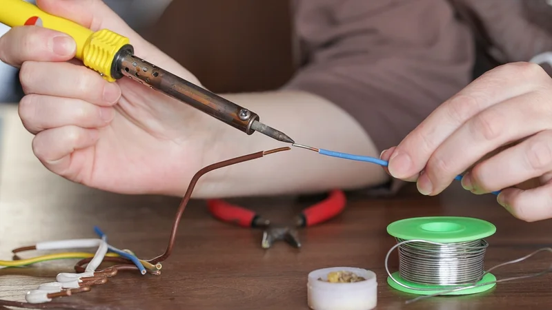
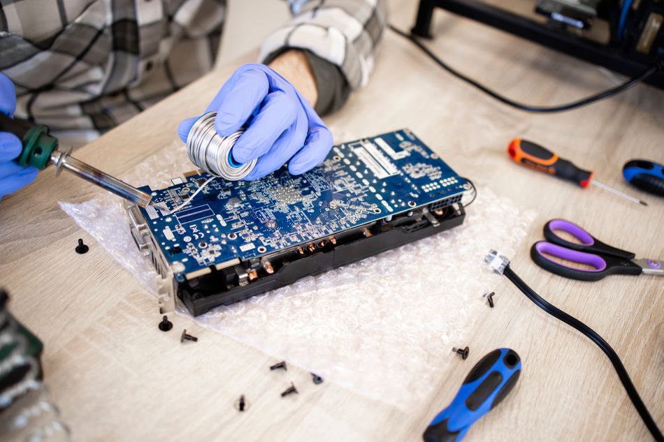
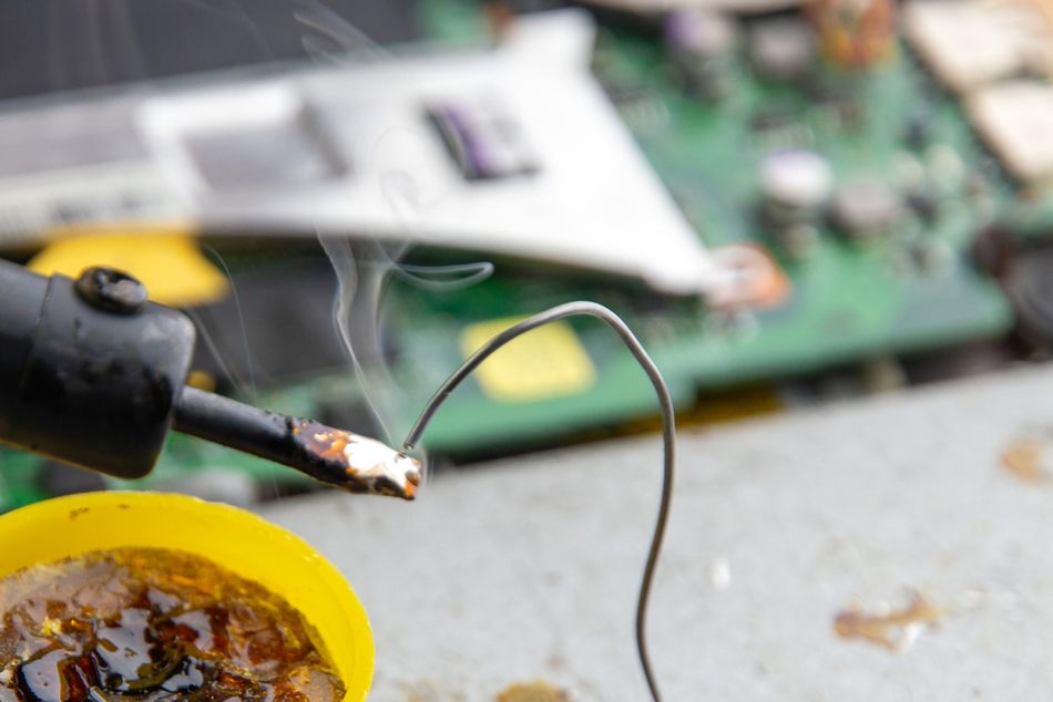
Solder Copper Wires with a Soldering Iron
Introduction
Soldering is a foundational skill for electronics engineers and hardware designers working across electronics, robotics, and embedded systems. Once assembling prototypes or repairing complex circuits, mastering how to solder wires ensures reliable electrical connectivity and long-term durability. This process involves joining metal conductors using solder, a fusible alloy that melts at low temperatures to form a solid, mechanical and electrical bond. Engineers must carefully manage heat, material compatibility, and insulation integrity to prevent cold joints or short circuits.
In professional settings, knowing how to solder wires extends beyond basic hand-soldering; it includes selecting proper solder types, using flux, and adhering to IPC and RoHS standards for quality assurance. This guide explores how to solder wires from both theoretical and practical perspectives, drawing on industry standards and up‑to‑date research.
Fundamentals of Soldering Wires
Soldering vs Welding and Brazing
Soldering is often mistaken for welding or brazing, but the three processes differ significantly in temperature, metallurgy, and application. Welding fuses base metals by melting them together to form a single metallurgical structure. Brazing, in contrast, uses a filler metal that melts above 450 °C but below the melting point of the base metals. The molten filler flows into the joint by capillary action, forming a strong bond without melting the base material.
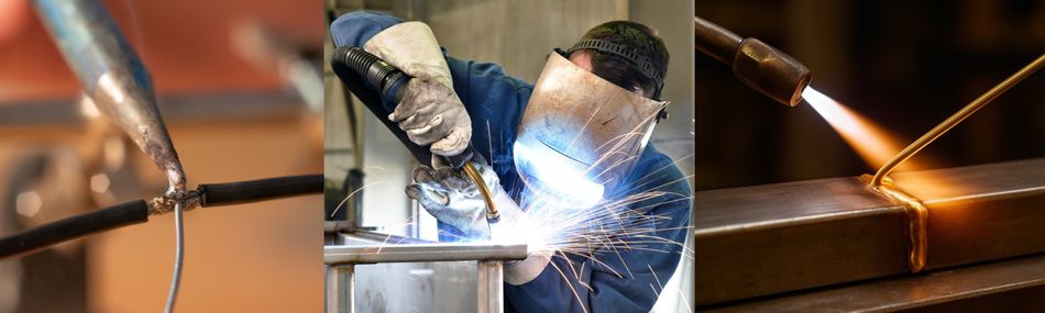
Soldering, however, employs a filler metal (solder) that melts below 450 °C, typically between 180 °C and 260 °C. [1] The base metals, often copper conductors, remain solid while the molten solder wets their surfaces and forms an intermetallic compound at the interface. This low-temperature process makes soldering ideal for delicate electronic assemblies that cannot tolerate the intense heat of welding or brazing.
Metallurgical Principles: Wetting and Intermetallic Bonds
The integrity of a solder joint depends on proper wetting and interatomic bonding. Wetting describes how molten solder spreads evenly over a clean metallic surface. Two opposing forces, surface tension and interfacial friction, resist this spreading, while interatomic attraction between tin and copper atoms promotes it. The reaction forms intermetallic compounds such as Cu₃Sn or Cu₆6Sn₅, which ensure both mechanical strength and electrical continuity.
For consistent wetting, all solder wires and joint surfaces must be free of oxidation, oil, or contamination. If oxidation is present, the solder will bead up, forming a “cold joint” with poor conductivity. Here, flux becomes indispensable; it dissolves oxides and prevents further oxidation during the soldering process.
Flux: Removing Oxides and Promoting Wetting
Flux acts as a chemical cleaning agent, removing surface oxides and keeping molten solder active until the joint forms. Without it, proper wetting cannot occur. The common flux types include:
Rosin (RMA) Flux, derived from natural resin, becomes active at soldering temperatures and leaves a mildly corrosive residue.
No‑Clean Flux, formulated to leave minimal residue that can remain on the joint without cleaning.
Water‑Soluble Flux, which contains organic acids; its residues are corrosive and must be cleaned with water.
Flux must melt at a lower temperature than the solder so that it can begin cleaning before the solder melts. Most solder wire for electronics contains a flux core that delivers flux automatically as the solder melts. For heavily oxidized copper wire, or when additional cleaning is required, external flux (paste, liquid or gel) may be applied.
Solder Alloys: Lead‑Based versus Lead‑Free
Historically, tin–lead (Sn‑Pb) alloys dominated electronics soldering because of their eutectic composition (63% tin and 37% lead) that melts sharply at 183 °C. [2] Sn‑Pb alloys offer good wetting, low cost and are easy to work with. However, lead is toxic, and regulations such as the EU RoHS Directive have driven the adoption of lead‑free solder.
Modern lead‑free solders commonly use tin with silver (Ag), copper (Cu) and sometimes bismuth (Bi). For example, Sn‑3.0Ag‑0.5Cu (SAC305) melts around 217 °C–219 °C. Lead‑free alloys require higher soldering temperatures (650–700 °F or 343–371 °C) and often include more aggressive flux to promote wetting. They may also exhibit different mechanical characteristics; silver adds strength but increases cost, while bismuth lowers the melting point.
Solder Wire Diameter and Wire Gauge Selection
Solder is available in diameters from 0.015 inch (0.38 mm) to 0.125 inch (3.18 mm). Finer solder (≤0.02 inch) is ideal for precision circuit board work, while thicker diameters (≥0.05 inch) are used for high-current joints, such as connecting speaker or automotive wires.
The American Wire Gauge (AWG) system describes the diameter of conductors and their current-carrying capacity. For example, AWG 20 wire has a diameter of 0.032 inch (0.8128 mm), a cross‑sectional area of 0.519 mm² and is rated at 11 A for chassis wiring. Selecting a wire gauge depends on the current, voltage drop and mechanical strength required. For general electronics prototyping, AWG 22–24 stranded wire is typically sufficient.
Recommended Reading: Comparing the Contrasts: Lead-Based vs. Lead-Free Solder
Tools and Materials for Soldering Wires
Soldering Irons and Stations
The soldering iron is the primary tool that delivers heat to the joint. Basic pencil irons provide fixed wattage (15–60 W) and are suitable for DIY or occasional electrical work. In contrast, soldering stations provide adjustable temperature control, interchangeable tips, and precise thermal stability, essential for professional engineering environments. The iron consists of a heating element, a thermally stable tip, and, sometimes, a temperature sensor. Premium tips are plated with iron and nickel to reduce erosion and improve heat transfer.
For wire soldering, a 40–60 W adjustable iron is often appropriate! The ability to set the temperature allows you to accommodate different solder alloys. Some stations feature sleep modes and digital displays for repeatability. For field work, a portable gas‑powered iron or battery‑powered tool may be used, but these lack precise temperature control.
Tip Selection
The tip of the soldering iron determines how efficiently heat reaches the joint. The conical tips provide precision for fine components and AWG 28–32 wires. The chisel or bevel tips offer greater contact area, suitable for AWG 14–20 wires, connectors, and terminal splices. It is advisable to replace worn or oxidised tips to maintain uniform heating and prevent excess solder blobs. Regular cleaning with a damp sponge or brass wool prevents oxidation buildup and ensures consistent solder flow.
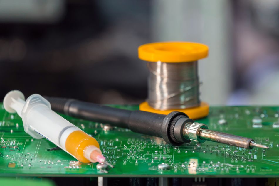
Solder Wire and Flux
Selecting the correct type of solder and flux directly affects the quality of every solder joint:
Flux‑Core Solder: Contains rosin core solder or no-clean flux for general electronics; convenient for routine applications.
Solid Wire Solder: Requires external flux; used for specialized jobs where you want to control the flux separately.
Lead‑Free Solder: Commonly SAC305 (Sn-3.0Ag-0.5Cu); ideal for RoHS-compliant assemblies but requires higher temperature and a slightly different technique.
Lead‑Based Solder: Sn-63/Pb-37 eutectic alloy; melts sharply at 183 °C, easier to melt solder and apply solder, but must be handled with care due to toxicity.
Flux is available as liquid, paste or gel! Many engineers use no‑clean flux pens for touch‑ups and water‑soluble paste for complex assemblies that will be washed. For high‑reliability applications, follow the flux classification in J‑STD‑004 and remove any required residue. [3]
Recommended Reading: Is Soldering Paste the Same as Flux? Differences Explained for Electronics Engineers
Wires and Insulation
Choosing the right wire and insulation is vital for safe, efficient connections:
Stranded Wire consists of many small strands twisted together. It is flexible and used in cables, robotics and assemblies subject to vibration. Because strands can spread when stripped (“birdcaging”), take care to avoid damaging them.
Solid Wire has a single conductor and is easier to insert into breadboards or connectors. It is more rigid and prone to breaking when bent repeatedly.
Insulation materials include polyvinyl chloride (PVC), cross‑linked polyethene (XLPE), fluoropolymer (PTFE) and silicone. [4] Silicone withstands high temperatures (>200 °C) and is ideal for soldering because it resists melting. For wires that will be exposed to soldering heat, select insulation with a temperature rating well above your soldering temperature.
Other materials include heat‑shrink tubing for insulation and strain relief, solder wick or desoldering braid for removing solder, solder suckers (vacuum pumps), wire strippers and third‑hand tools to hold wires in place.
Additional Tools and Accessories
The essential accessories improve precision, comfort, and safety:
Heat Shrink Tubing: Provides insulation and strain relief after soldering; shrink with a heat gun for a secure seal.
Solder Wick or Desoldering Braid: Removes excess solder cleanly during rework.
Solder Sucker: Vacuum-based tool for quick solder removal from through hole joints.
Wire Strippers and Pliers: Used to prepare and manipulate conductors before making wire joints.
Alligator Clips or Helping Hands: Hold components steady, prevent burns, and improve heat transfer control.
Work Surface: A heat-resistant mat prevents damage and stabilizes your setup.
Personal Protective Equipment and Safety Gear
Soldering generates lead dust (for Sn‑Pb alloys) and rosin flux fumes. Lead exposure occurs primarily through ingestion when contaminated surfaces contact the mouth; rosin fumes can cause respiratory irritation or asthma. To minimize the risk:
Use a fume extractor or work near a ventilated hood to capture flux vapors.
Wear safety glasses or a face shield to protect eyes from splashes or flying solder.
Wash your hands after soldering and avoid eating or drinking in the soldering area.
Use heat‑resistant gloves or finger cots when handling hot wires.
Secure the soldering iron in a stable stand and unplug it when not in use.
Proper tools and safety discipline ensure efficient solder connections, clean wire joints, and professional-grade results every time.
Recommended Reading: How to Remove Solder from a Circuit Board (Comprehensive Desoldering Guide)?
Preparing for a Solder Joint
Stripping Insulation and Avoiding Birdcaging
Proper preparation is essential for a reliable solder joint! Begin by measuring the amount of insulation to be removed. Begin by measuring how much insulation to remove from the ends of the wires. For through-hole soldering, expose only one to two conductor diameters (approximately 1.5 mm) of bare wire beyond the termination. When inserting into connectors or cup terminals, strip just enough insulation for the strands to reach the bottom of the cup.
Use a calibrated wire stripper rather than a knife to prevent nicking or breaking strands. After stripping, avoid “birdcaging,” where the strands flare out. If necessary, twist the strands gently to retain the circular shape. In high‑reliability applications, any nicked or severed strands may necessitate cutting back and re‑stripping.
Cleaning and Applying Flux
Contaminants such as oils, fingerprints, or oxidation hinder wetting and prevent proper bonding of the solder. It is necessary to clean each copper wire with isopropyl alcohol or an approved electronics cleaner, then let it dry completely.
Next, apply soldering flux to the exposed metal! Flux pens distribute a thin, uniform layer, while brushes work best for paste or gel flux. Use only a small amount of solder flux—excessive application can trap heat, extend soldering time, or cause residue buildup. Clean preparation ensures consistent heat transfer and proper solder wetting during joint formation.
Pre‑Tinning Wires
Tinning coats the bare wire with a thin, even layer of solder before joining. It improves solder flow, enhances conductivity, and reduces oxidation during soldering. To effectively pre‑tin:
Clamp the stripped wire to prevent it from moving.
Heat the conductor with the soldering iron tip placed beneath it to transfer heat through the wire.
Apply solder to the top side of the wire (not directly to the iron). The solder should melt and flow into the strands.
Remove the solder and iron when the entire exposed section is coated; avoid wicking solder under the insulation.
Inspect the tinning. The solder should cover at least 95% of the strands with a smooth, bright coating.
Pre-tinning reduces final soldering time, ensures uniform wetting, and maintains alloy consistency, especially when using lead-free solder. It also creates a strong foundation for splicing and assembling solder wires in multi-strand applications.
Recommended Reading: Soldering Temperature: Optimizing Heat for Reliable Electronic Assemblies
Step‑by‑Step Guide: How to Solder Wires
1. Gather Materials and Set Up the Workstation
Before learning how to solder wires, organize your tools and ensure a clean, stable work surface. You will need a soldering iron with a clean soldering iron tip, solder wire, flux, wire strippers, cutters, heat shrink tubing, helping hands or a third-hand jig, and PPE.
Power on the soldering iron and set its temperature according to the type of solder. For Sn-Pb alloys, use 600–650 °F (315–343 °C); for lead-free solder, use 650–700 °F (343–371 °C). Place the heat shrink tubing on one wire before joining, as it cannot be added afterwards. A fume extractor or well-ventilated area is essential to prevent inhalation of flux fumes.
2. Align and Splice the Wires
There are several methods to physically join wires before soldering. Choose based on mechanical strength requirements and space constraints.
Twist (Rat‑Tail) Splice: Twist two pre-tinned stranded wires together clockwise 4–5 turns, then apply solder to cover the twisted section. This method works well for DIY or low-stress electrical work inside harnesses.
Western Union (Lineman’s) Splice: For stronger wire joints, use this professional splice. Cross the stripped ends, wrap each wire around the other’s axis three or more turns, and melt solder over the overlap. Finish with heat-shrink tubing for insulation and strain relief. This design maintains mechanical integrity even before soldering.
J‑Hook or Hook Splice: Form each wire end into a hook, interlock them, pinch lightly, and apply solder until the joint forms a smooth solder flow. Use this when attaching to terminals, posts, or connectors.
Splicing to Terminals and PCBs: Insert the tinned copper wire into the terminal cup until it touches the base. Fill 75–90 % of the cup with solder, forming a concave meniscus. Ensure insulation reaches the cup edge with minimal gap (0D–1D).
For through-hole PCB joints, insert the wire through the plated hole. Allow 0–1.5 mm of insulation above the circuit board. The solder joint should wet both the pad and conductor thoroughly.
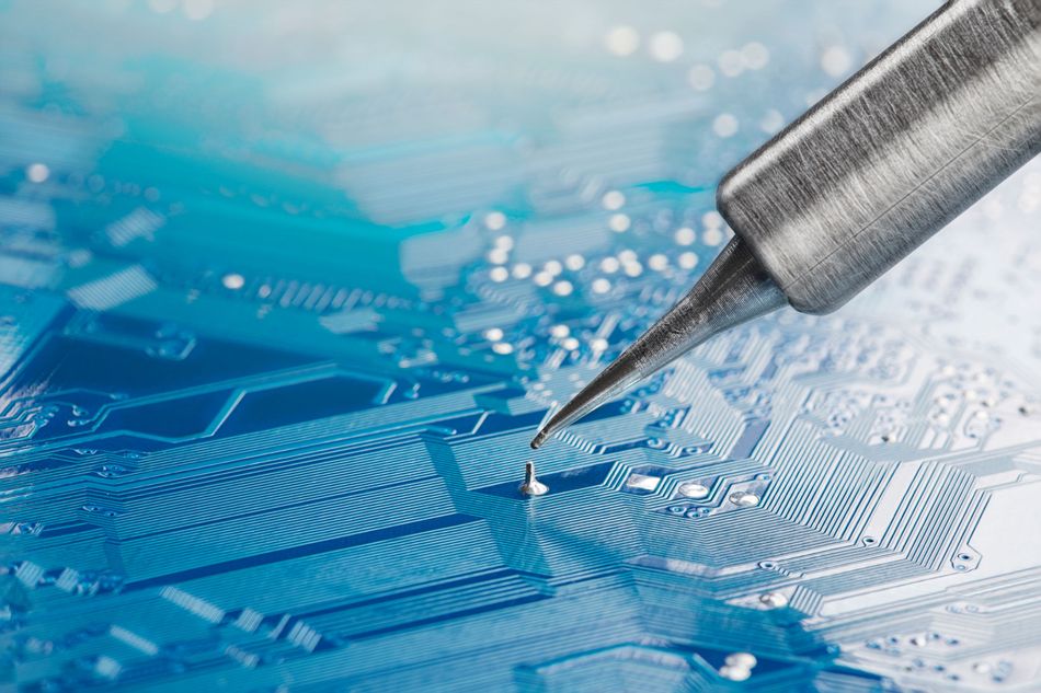
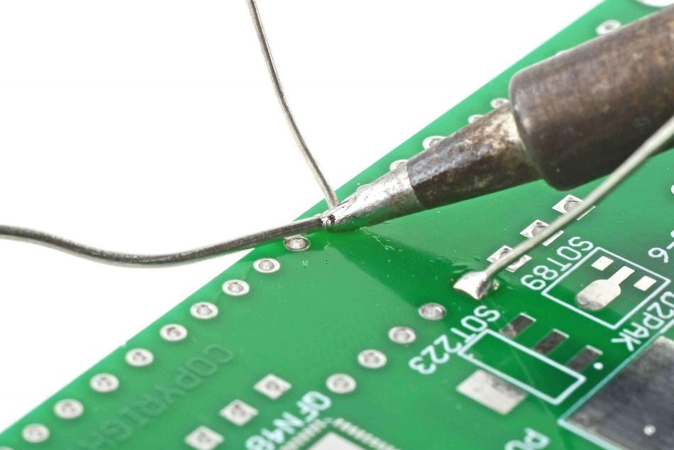
3. Heating and Applying Solder
Place the soldering iron tip against both the wire and the terminal or splice to heat the joint evenly. Hold the solder wire so that it touches the heated metal, not the iron. The solder should melt and flow into the joint. Maintain the heat just long enough for the solder to wet all surfaces and form a concave meniscus. Remove the solder wire first, then the iron. Avoid moving the joint until the solder solidifies; movement can cause a grainy “cold joint.”
Control heat carefully. If the insulation begins to melt, reduce the temperature or increase the contact area to transfer heat more efficiently. Overheating can damage components or make solder brittle.
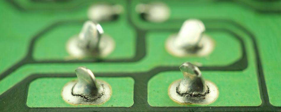
4. Inspecting the Joint
A proper solder joint has a shiny, smooth and concave appearance. For a cup terminal, a vertical fill of 75 %–100 % with complete circumferential wetting indicates a good joint. In a splice, the solder should envelop the strands without blobs or excess buildup. If the joint looks dull, chalky or has a “ball” shape, it may be a cold joint or one with poor wetting.
5. Cleaning and Strain Relief
After soldering, remove any flux residue if using rosin or water‑soluble flux. Use isopropyl alcohol and a lint‑free swab. Then slide the heat‑shrink tubing over the joint and apply hot air until it shrinks tightly. This provides insulation and strain relief, preventing mechanical stress from damaging the joint.
Example Table: Recommended Parameters for Common Wire Sizes
| AWG Size | Typical Application | Wire Diameter (mm) | Recommended Solder Diameter | Tip Type | Iron Temperature (°C) |
| 30 – 26 | Fine Signal Wires, Ribbon Cables | 0.25–0.40 | 0.5 mm (0.02 in) | Conical | 315–343 (Sn‑Pb) / 343–371 (lead‑free) |
| 24 – 22 | PCB Hookup Wires, Harnesses | 0.51–0.64 | 0.8 mm (0.03 in) | Chisel | 320–350 (Sn‑Pb) / 350–370 (lead‑free) |
| 20 – 18 | Power Leads, Speaker Wires | 0.82–1.02 | 1.0 mm (0.04 in) | Chisel / Bevel | 330–370 (Sn‑Pb) / 360–380 (lead‑free) |
| 16 – 14 | Automotive Cables, Servo Wires | 1.29–1.63 | 1.2–1.6 mm (0.047–0.063 in) | Bevel | 350–380 (Sn‑Pb) / 370–400 (lead‑free) |
These parameters serve as guidelines. Always verify that your iron can maintain thermal capacity when soldering thicker wires.
Recommended Reading: Solder Reflow: An In-Depth Guide to the Process and Techniques
Troubleshooting and Avoiding Common Errors
Cold Joints
A cold joint occurs when the solder does not fully melt or fails to wet the surfaces. It appears dull, porous, or lumpy, and has low mechanical strength. Causes include insufficient heat, oxidized surfaces, a dirty tip or moving the joint while the solder solidifies. Remedy by reheating the joint with fresh flux and solder until it takes on a shiny appearance.
Insufficient Wetting or Dewetting
If solder beads up on the wire or pulls back from the surface (dewetting), it indicates contamination or oxide layers. Clean the surfaces thoroughly, apply more flux and use the proper temperature. Replace oxidized soldering tips and ensure that the iron is not coated with old flux residues.
Overheating and Burned Insulation
Holding the iron on the joint too long can char the insulation, melt wire strands or delaminate PCB pads. Adjust the temperature, use a larger tip to increase heat transfer and practice efficient technique. Remember that lead‑free solder requires more heat than Sn‑Pb, so pre‑tinning both parts can reduce soldering time.
Solder Bridges and Excess Solder
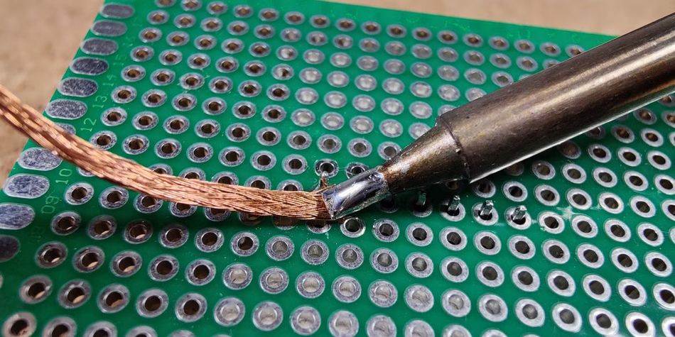
Applying too much solder can create bridges between adjacent conductors or pads, causing short circuits. Use just enough solder to form a concave fillet. The extra solder can be removed with desoldering braid: place the braid on the joint, heat it with the iron, and the solder will wick into the braid.
Damaged Wire Strands and Birdcaging
Nicked or broken strands reduce current‑carrying capacity and mechanical strength. Always use a proper wire stripper and inspect the conductor. If many strands are damaged, cut and strip again. Keep the strands twisted when inserting into terminals to avoid birdcaging.
Mixed Metallurgies
Avoid mixing different solder alloys in a joint, as this can create brittle intermetallic compounds. When joining lead‑free components with Sn‑Pb solder, remove as much old solder as possible and pre‑tin with the desired alloy.
Recommended Reading: Types of Solder: A Comprehensive Guide for Engineering Professionals
Safety Considerations
Lead Exposure and Flux Fumes
Lead is primarily a hazard when ingested. Lead dust from solder can contaminate hands and work surfaces; ingestion can lead to neurological and reproductive effects. Rosin‑based flux fumes contain irritants that can cause asthma and respiratory irritation. Lead‑free solder often requires higher temperatures and more active flux, which can generate more fumes. Use local fume extraction and avoid inhaling vapors.
Burns and Electric Shock
Soldering irons operate at temperatures exceeding 300 °C; accidental contact can cause severe burns. Keep the iron in its stand when not in use. Never place a hot iron on the bench. Electrical shock is possible if the iron is poorly grounded. Use compliant, double‑insulated equipment and test for proper earth grounding.
Workspace Practices
Clear the workspace of flammable materials and secure loose clothing and long hair. Do not eat or drink in the soldering area. Wash your hands after soldering, especially before touching your face or handling food. Follow your institution’s environmental health and safety policies for lead handling and waste disposal.
Strain Relief and Mechanical Integrity
Soldered splices can become brittle under vibration. The soldered connections may not be ideal for wires subject to repeated flexing; in such cases, consider crimp terminals or connectors. When using solder, always provide strain relief using heat‑shrink tubing, lacing or cable clamps to transfer mechanical load away from the solder joint.
Industry Standards and Best Practices
Professional electronic assemblies adhere to rigorous standards to ensure reliability.
The following guidelines derive from IPC‑J‑STD‑001 (Requirements for Soldered Electrical and Electronic Assemblies), IPC‑A‑610 (Acceptability of Electronic Assemblies) and IPC/WHMA‑A‑620 (Requirements and Acceptance for Cable and Wire Harness Assemblies):
Insulation Stripping: Do not nick or sever conductor strands. For through‑hole terminals, expose only 0D–2D (≤1.5 mm) of bare conductor.
Pre‑Tin Coverage: At least 95% of the conductor surface should be tinned.
Cup Terminal Solder Fill: The cup should be filled 75% – 100%, with the solder wetting both the conductor and terminal wall.
Lineman’s Splice Wraps: Use at least three turns of each wire around the other for mechanical strength.
Through‑Hole Vertical Fill: Solder should fill the hole and form a meniscus on both sides of the PCB.
Inspection: Acceptable joints are shiny and concave with no voids, cracks or burnt insulation. Reject joints that are dull, spiky, have insufficient wetting or expose bare conductors beyond the specified length.
Cleaning: Remove corrosive flux residues using appropriate solvents and equipment; some no‑clean fluxes may be left in place if permitted by the product specification.
Following these standards helps ensure that soldered connections meet the performance and reliability requirements of industrial electronics.
Recommended Reading: Solderability Test - Principles, Methods, and Applications in Electronics Manufacturing
Future Trends and Market Outlook
The soldering field is evolving due to environmental regulations, miniaturization and automation. Lead‑free solders are now the default for most commercial electronics, driven by IPC, RoHS and similar regulations.
The global Tin-based Lead-Free Solder Market is poised for significant expansion, projected to reach approximately USD 7,000 million by 2066, growing at a robust CAGR of 6.3%. Lead‑free alloys will account for 54.2 % of the market share in 2025, reflecting the ongoing replacement of leaded solder. The demand is particularly strong for low-voiding, halogen-free fluxes, which minimize environmental impact and improve solder joint reliability by reducing corrosion and oxidation during reflow.
Emerging manufacturing trends emphasize precision and repeatability! The automated soldering systems—including robotic selective soldering, laser soldering, and induction-based heating—enable controlled heat transfer and minimize operator variability. These solutions are vital for high-density circuit board production, where manual soldering iron techniques may be impractical.
In wire harness production, hybrid techniques that combine machine crimping with selective soldering deliver uniform solder wires and reproducible results. Digital process control and IoT-enabled monitoring now allow engineers to adjust temperature profiles, flux application, and tinning consistency remotely.
Conclusion
Soldering wires may appear simple, yet achieving reliable, high‑quality joints requires understanding materials, controlling heat and following rigorous procedures. Well-executed solder joint ensures electrical reliability, mechanical strength, and long-term performance across countless applications, from circuit boards to wire harnesses. Understanding proper tinning, flux selection, and heat transfer control is essential to achieving consistent results and avoiding costly rework.
While lead-free solder and halogen-free fluxes dominate modern electronics due to environmental standards, traditional hand-soldering still plays a vital role in prototyping, repair, and small-batch production. Advances in soldering iron technology, real-time temperature control, and automated soldering systems now bridge the gap between manual craftsmanship and industrial scalability. This art of soldering is an engineering discipline that combines precision, material science, and design awareness to create reliable, high-performance electrical connections.
Frequently Asked Questions (FAQ)
Q. Why should I pre‑tin wires before soldering?
A. Pre-tinning helps solder wires together faster by improving wetting and reducing the time needed to heat up the joint. It ensures a smooth, durable, good connection with minimal insulation damage.
Q. What temperature should I use when soldering wires?
A. For tin–lead (Sn‑Pb) solder, set your iron to 600–650 °F (315–343 °C). Lead‑free solders such as Sn‑3.0Ag‑0.5Cu require higher temperatures, typically 650–700 °F (343–371 °C). It is better to adjust your soldering iron temperature based on wire size and tip contact area for consistent heating.
Q. How do I choose the right solder wire diameter?
A. For fine wires (AWG 30–26), use 0.5 mm solder; for larger wires (AWG 16–14), use 1.2–1.6 mm. Use the table in the article to ensure correct solder flow, avoiding flooding or weak joints.
Q. Are lead‑free solders as reliable as lead‑based solders?
A. Yes. With proper flux and temperature control, lead-free solder provides a good connection. Most modern electrical practices and industries now use lead-free materials to comply with RoHS.
Q. How can I avoid cold joints?
A. To avoid cold joints, clean the surfaces, pre-tin, and maintain stable heat. Follow a step-by-step approach, holding the joint still until the solder cools into a shiny finish.
Q. Can I solder materials other than wires, like a copper pipe or spark plug?
A. Yes, but the method differs. Copper pipe soldering requires higher heat and plumbing flux, while spark plug soldering demands precise temperature control and compatible alloys for electrical continuity.
References
[1] Copper. Soldering and Brazing of Copper and Copper Alloys [Cited 2025 October 30] Available at: Link
[2] ResearchGate. Electronic Properties and Viscosity of Liquid Pb—Sn Alloys [Cited 2025 October 30] Available at: Link
[3] Electronics. Selection of Wave Soldering Fluxes for Lead-Free Assembly [Cited 2025 October 30] Available at: Link
[4] Allied Wire. Types of Insulation Materials for Wire and Cable [Cited 2025 October 30] Available at: Link
in this article
1. Introduction2. Fundamentals of Soldering Wires3. Tools and Materials for Soldering Wires4. Preparing for a Solder Joint5. Step‑by‑Step Guide: How to Solder Wires6. Troubleshooting and Avoiding Common Errors7. Safety Considerations8. Industry Standards and Best Practices9. Future Trends and Market Outlook10. Conclusion11. Frequently Asked Questions (FAQ)12. References